
ITT we discuss turbo cranes (again)
 12-07-2014, 07:42 PM
#1
Elite Member
Thread Starter

Join Date: Apr 2010
Location: Newcastle, Australia
Posts: 2,826
Total Cats: 67
Hey,
To start with, Id like to understand how cranes work, as far as I can see a crane typically is used to take the downward force (weight) of the turbo, and help relieve the manifold of this weight.
Does it also damp vibration? Is this a key goal?
Also if a long tube manifold is tied to the engine at the turbo end, when it heats up and expands isnt the crane putting more stress on the manifold that wouldnt otherwise be there?
I had a crane made, it was quite expensive and Im annoyed that the reult was broken turbo bolts. This tells me just how much force holding the turbo in one place in relation to the engine put on the manifold, because of expansion with heat.
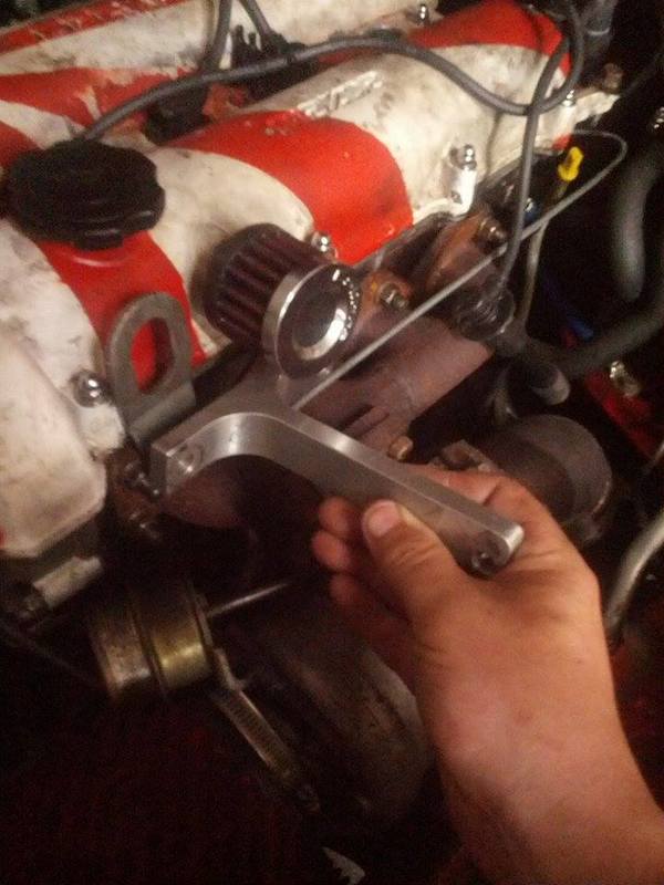
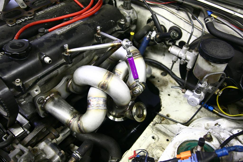
Heres pics.
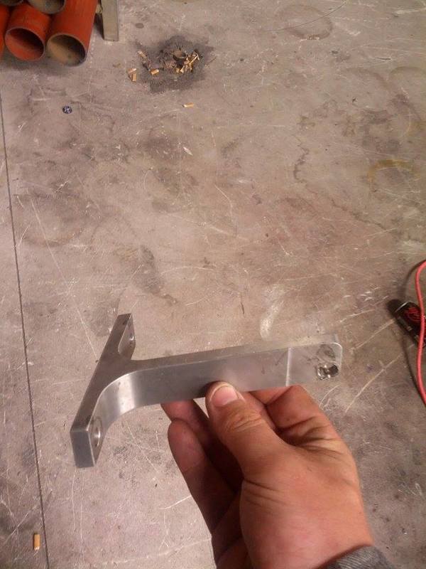
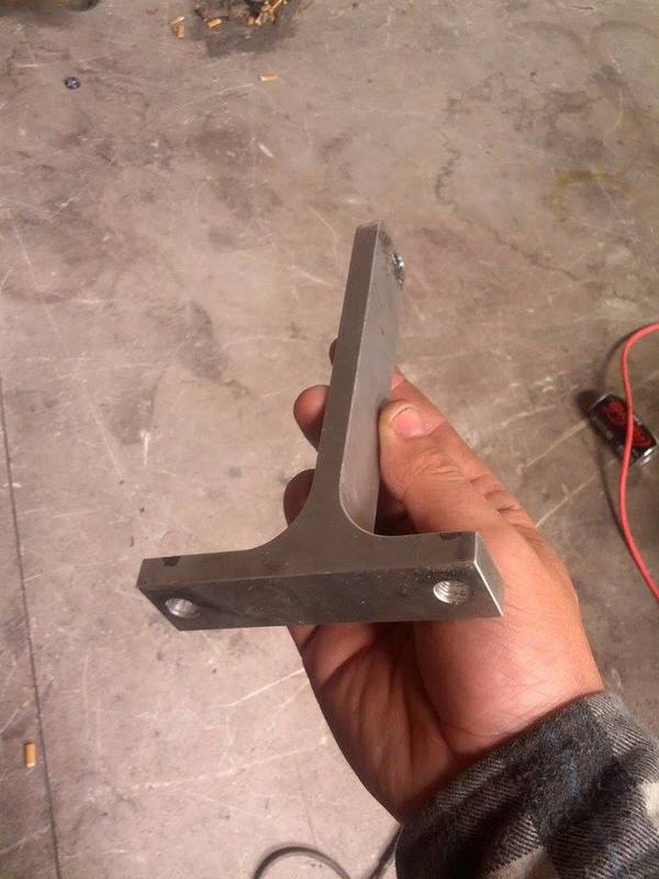
Different car just showing mounting location.
Discuss
Dann
To start with, Id like to understand how cranes work, as far as I can see a crane typically is used to take the downward force (weight) of the turbo, and help relieve the manifold of this weight.
Does it also damp vibration? Is this a key goal?
Also if a long tube manifold is tied to the engine at the turbo end, when it heats up and expands isnt the crane putting more stress on the manifold that wouldnt otherwise be there?
I had a crane made, it was quite expensive and Im annoyed that the reult was broken turbo bolts. This tells me just how much force holding the turbo in one place in relation to the engine put on the manifold, because of expansion with heat.
Heres pics.
Different car just showing mounting location.
Discuss
Dann

Reply
 0
0

0
 12-09-2014, 11:24 AM
#3

This is my engineering opinion after considering the system, I've never used a turbo crane before. I think for a turbo crane to really be effective it needs to allow the manifold to flex in and out from the engine and also front to back and allow some twist. So in my mind there needs to be a pair of rod ends involved in the connection. And furthermore it should connect at more or less directly above the center of mass of the turbo setup pointing more or less straight up to reduce the moment it would generate. The trick part is really figuring out where the center of mass is once you've bolted a down pipe onto the back of the turbo since that adds weight but it also adds it own mount.
Our motors also have **** for placement options for something mounted above. Maybe a turbo "jack" would be a better idea since theres a bunch of good places to bolt to on the side of the motor.
Our motors also have **** for placement options for something mounted above. Maybe a turbo "jack" would be a better idea since theres a bunch of good places to bolt to on the side of the motor.
Reply
0
0

 12-09-2014, 12:36 PM
#7
Mcmastercarr has some pretty cool cable ends that retain something like 98% cable strength. They are adjustable and available in stainless. 20 bucks a piece for the size I purchased on a totally unrelated project.
Edit: I just looked, the end is not actually adjustable, but it would be easy to add an adjustable link.
Edit: I just looked, the end is not actually adjustable, but it would be easy to add an adjustable link.
Reply
0
0
12-09-2014, 12:42 PM
#8
Supporting Vendor

iTrader: (3)

Join Date: Jul 2006
Location: San Diego
Posts: 3,303
Total Cats: 1,216
This kind of relates to something I've been wondering for a long time regarding turbo mount orientation. I've got a manifold from the prehistoric age, but it is a top mount - and with the addition of inconel studs, have not had any turbo -> manifold attachment issues. In nearly every first-hand case I've seen of side-mount turbos on BPs, the owner has struggled continuously - even with the standard inconel upgrades - with studs backing out, mating issues under heat, etc.
Bottom - mount setups appear to be about 50/50 in terms of users having issues or not.. so is the "least desireable" turbo orientation actually secretly the most desireable?
And more directly related to the OP topic, if I were designing a turbo brace (which I've considered a couple time but haven't seen a pressing need in my case) for a top-mount I would do a a "jack" style as Leafy puts it, supporting from below, with heim joints. For a bottom mount turbo, a crane makes the most sense.
-Ryan

Last edited by ThePass; 12-09-2014 at 01:18 PM.
Reply
0
0
12-09-2014, 12:49 PM
#9
Elite Member

iTrader: (9)
Join Date: Jun 2006
Location: Chesterfield, NJ
Posts: 6,892
Total Cats: 399
This is my engineering opinion after considering the system, I've never used a turbo crane before. I think for a turbo crane to really be effective it needs to allow the manifold to flex in and out from the engine and also front to back and allow some twist. So in my mind there needs to be a pair of rod ends involved in the connection. And furthermore it should connect at more or less directly above the center of mass of the turbo setup pointing more or less straight up to reduce the moment it would generate. The trick part is really figuring out where the center of mass is once you've bolted a down pipe onto the back of the turbo since that adds weight but it also adds it own mount.
Our motors also have **** for placement options for something mounted above. Maybe a turbo "jack" would be a better idea since theres a bunch of good places to bolt to on the side of the motor.
Our motors also have **** for placement options for something mounted above. Maybe a turbo "jack" would be a better idea since theres a bunch of good places to bolt to on the side of the motor.
Reply
0
0
12-09-2014, 07:57 PM
#10
Elite Member
Thread Starter
Join Date: Apr 2010
Location: Newcastle, Australia
Posts: 2,826
Total Cats: 67
The brace that I posted pics of doesnt really allow any movement in any direction, and I can see heim join braces allowing movement in a set spherical path however they dont address things like the manifold moving up or down in relation to the engine when heated.
Is there any info or does someone have a folder full of photos from pro race team braces?
Cheers,
Dann
Is there any info or does someone have a folder full of photos from pro race team braces?
Cheers,
Dann
Reply
0
0
12-09-2014, 09:04 PM
#11
Elite Member
Thread Starter
Join Date: Apr 2010
Location: Newcastle, Australia
Posts: 2,826
Total Cats: 67
Typing "F1 turbo" into google images basically just shows a trillion triangular pyramid braces with a heim joint directly over the turbo most bolted to the rear housing.
A bunch of the manifolds look like they will move a lot under heat also..
Dann
A bunch of the manifolds look like they will move a lot under heat also..
Dann
Reply
0
0
 12-10-2014, 12:34 AM
#16
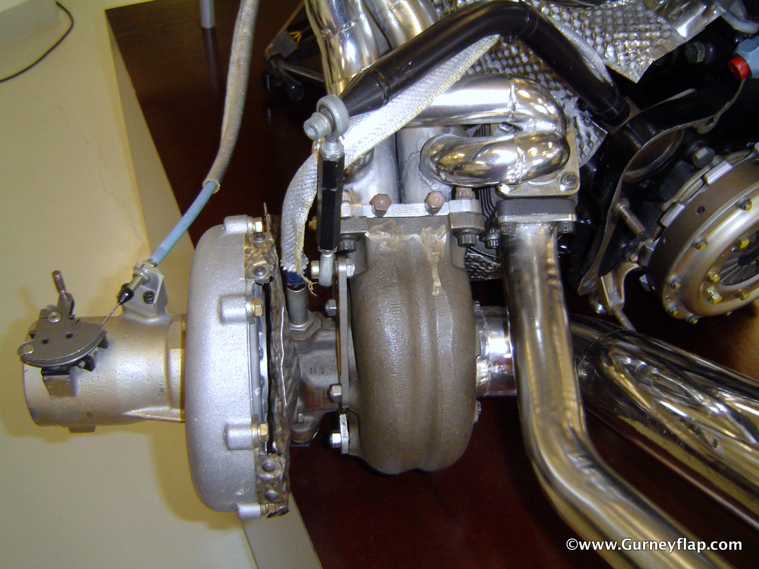
I went with the bottom support idea. :2cents
To see pic, go to post #8 most of the way down.
https://www.miataturbo.net/diy-turbo...o-build-79259/
No issues with the bolts so far. The downpipe is also supported off the trans.
Cheers,
-Jeff
To see pic, go to post #8 most of the way down.
https://www.miataturbo.net/diy-turbo...o-build-79259/
No issues with the bolts so far. The downpipe is also supported off the trans.
Cheers,
-Jeff
Reply
0
0
 12-10-2014, 11:48 AM
#18
There's an older thread on the subject where I had the idea to also hard mount the exhaust to the middle or back of the PPF to completely get rid of the effect and to more or less let the whole exhaust move with the engine but no one was buying it at the time. It pretty much operates under the assumption that without miss matched mount stiffnesses (IE engine and diff mounts are allow around the same amount of flex) that the PPF doesnt get twisted all that much while driving.
Reply
0
0
12-10-2014, 12:07 PM
#19
mkturbo.com

iTrader: (24)
Join Date: May 2006
Location: Charleston SC
Posts: 15,176
Total Cats: 1,680
I talked to JKav a good while back about bracing. If I remember correctly he was not a huge fan of cranes. Hew much preferred to use a mount that attaches to the engine block and goes up to the bottom of the turbo. I asked him for some pictures of how he was going to do it, but I never received them.
Reply
0
0
12-10-2014, 12:37 PM
#20

I talked to JKav a good while back about bracing. If I remember correctly he was not a huge fan of cranes. Hew much preferred to use a mount that attaches to the engine block and goes up to the bottom of the turbo. I asked him for some pictures of how he was going to do it, but I never received them.
Reply
0
0


