
Post your DIY aero pics
 06-14-2015, 11:47 PM
#861
Newb

Join Date: Jun 2015
Posts: 2
Total Cats: 0
The aircraft winglet case is a little bit different than what we are playing with for our wings.
The goal with winglets is to get better fuel burn through increasing the effective aspect ratio of the wing (wingspan / wing chord) without physically increasing it to stay within gating sizes. Additionally they are operating in a region where the business cased doesn't benefit quickly from increasing flight speeds due to the supercritical airfoils performance degrading quickly, but rather minimizing the drag at a specific cruise condition that the majority of time is spent at.
If you imagine a wing section in a wind tunnel that spans from wall to wall the effective aspect ratio is infinite, and the sectional properties match that of the 2d analysis case of the airfoil. As you move away from that case the span efficiency term drops due to the mixing of the low and high pressure zones.
We're trying to get the greatest amount of downforce with a minimal drag penalty from our wings, where the optimal configuration will be track dependent. As has likely been mentioned before the end plate shape is usually driven by the thicker boundary layer on the upper side of the airfoil (closer to the ground in our case) cause by the low pressure region driving a taller endplate on the low pressure side relative to the high pressure side (3:1 ratio). The distance that the endplate projects forward into flow being a smaller fraction (less than .1) of the chord, with the optimal varying based on the loading & Re of the section, and aft driven to around .15 of the chord.
For our design points the induced drag (drag due to downforce) is substantially larger than the parasitic drag (skin friction drag) from the wetted surface area of the wing and endplates, with this trade growing quickly at increasing velocities.
Bit of a rant but I hope the info helps somebody make a logical choice with their DIY aero work!

Reply
 0
0

0
07-12-2015, 04:42 AM
#862
Junior Member

Join Date: Jun 2014
Location: Purga, Queensland, Australia
Posts: 86
Total Cats: 10
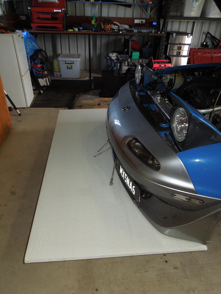
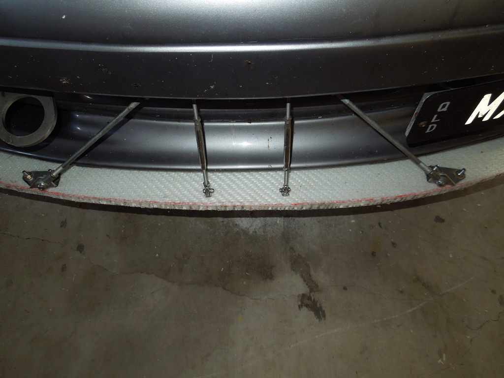
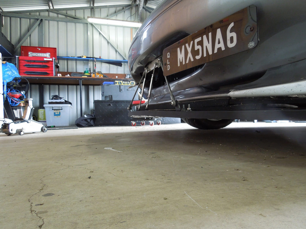
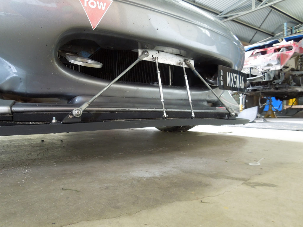
I have made 3 splitters to date. The mounts I use are here KazeSpec Engineering splitter hardware kits - MiataRoadster - High-performance customer service...and parts for Roadsters
Version 1 - 9.7 kg (ABS Plastic)
Version 2 - 7.2 kg was made from ply 10mm with 2 layers of fibreglass on the bottom and 1 on the top. It has lasted quite well to be honest.
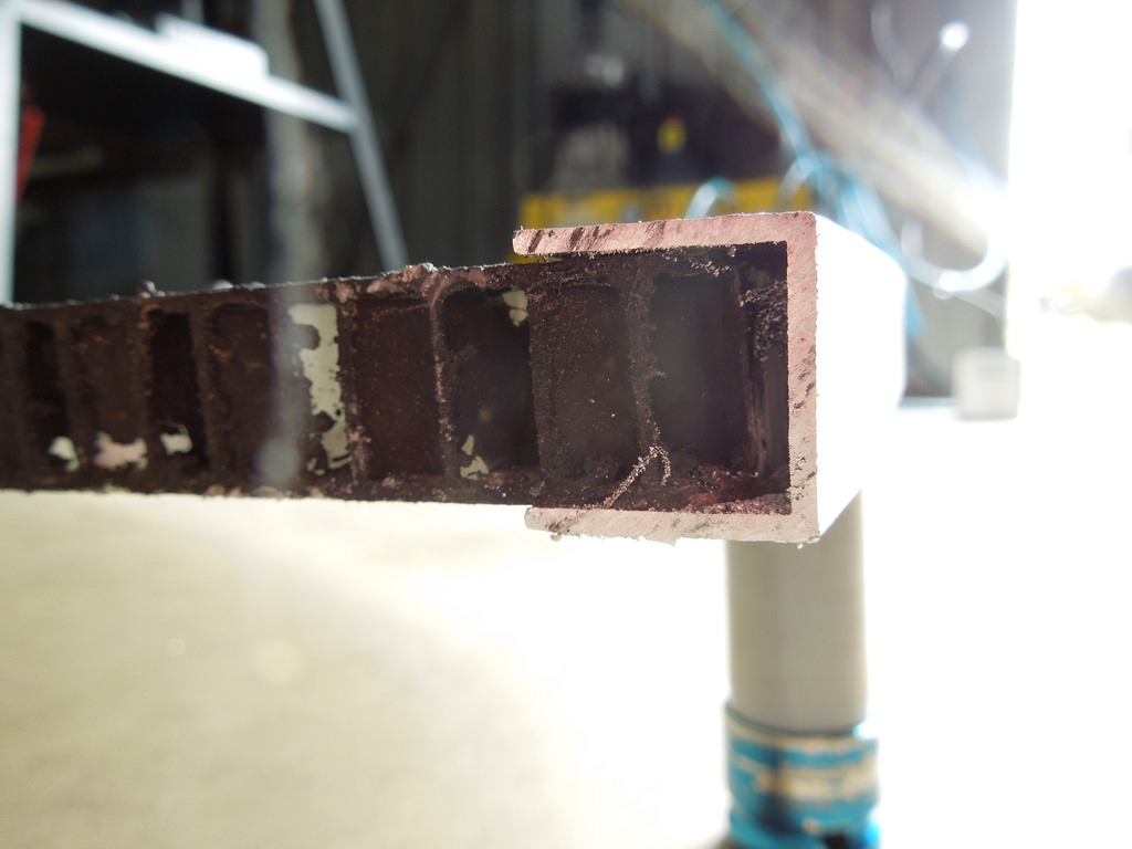
Version 3 - 5 kg is made from 17mm Monopan Sandwich Panel ? MonoPan � Lavender CE Pty Ltd. This stuff is strong and light! However the edge does not take drilling too well. I'm getting some 1.6mm x 17mm U channel aluminium to put around the leading edge to protect it. Enough Monopan to make 2 splitters cost about $250. It is easy to cut but a bit painful to shape and trim. In the end I got an air angle grinder out and this worked well. Note this is also a bit bigger than the other 2 but weights LESS.
Version 3...
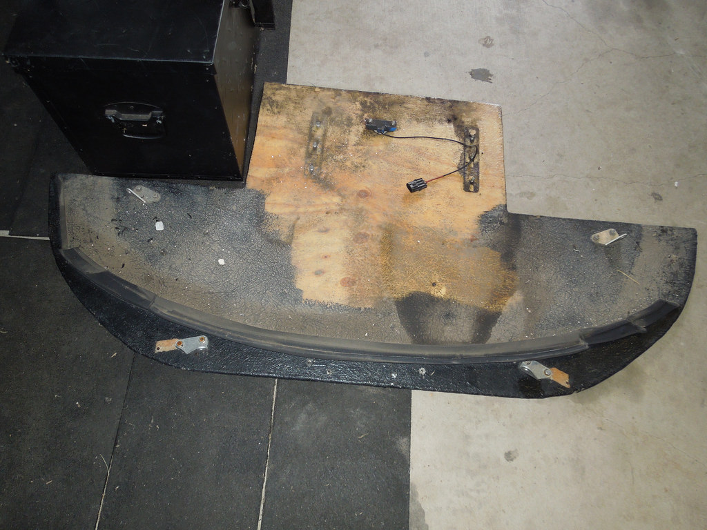
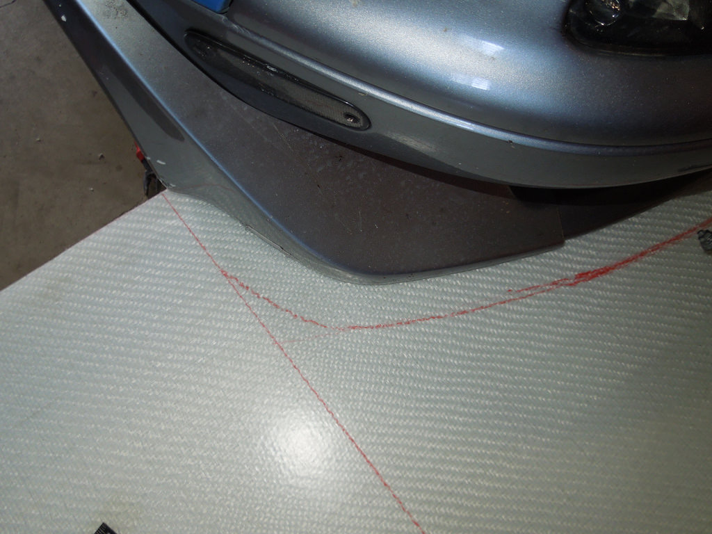
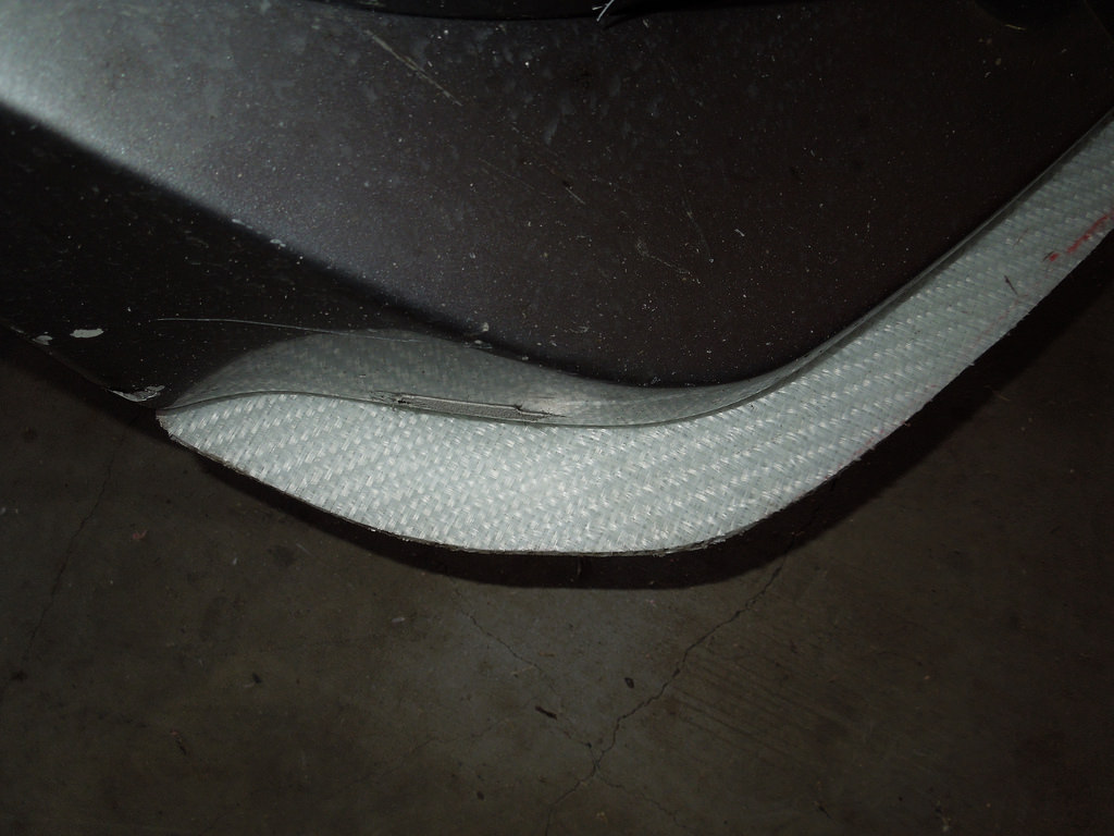
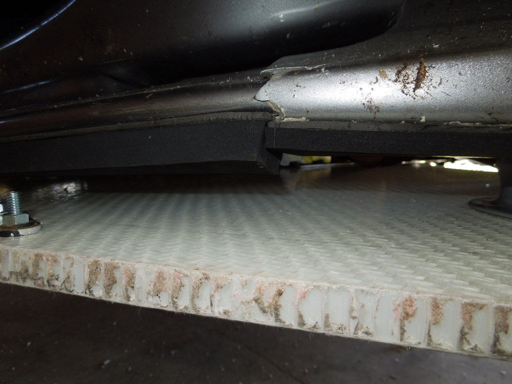
Monopan under the front after V2 splitter removed
 DSCN2609 by Eipeip, on Flickr
Version 2 - after about 18 months of use.
 DSCN2607 by Eipeip, on Flickr
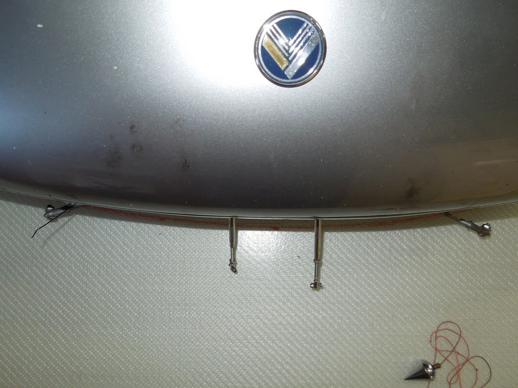
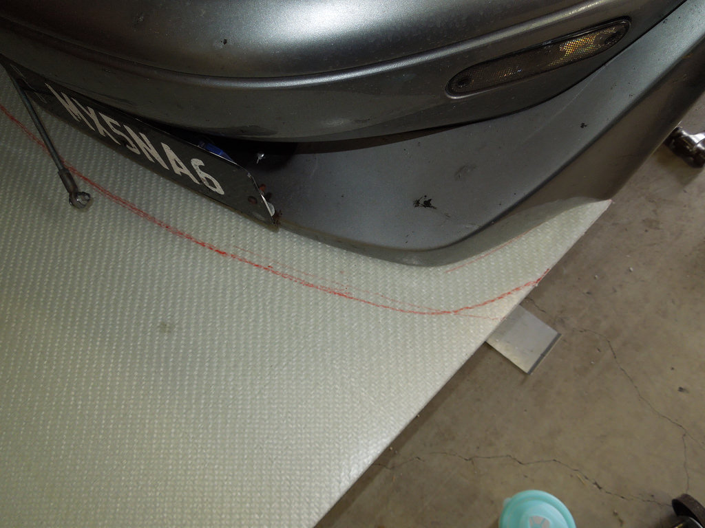
Starting to mark out (the red dot in the middle is in the flash shadow)
 DSCN2613 by Eipeip, on Flickr
 DSCN2612 by Eipeip, on Flickr
 DSCN2615 by Eipeip, on Flickr
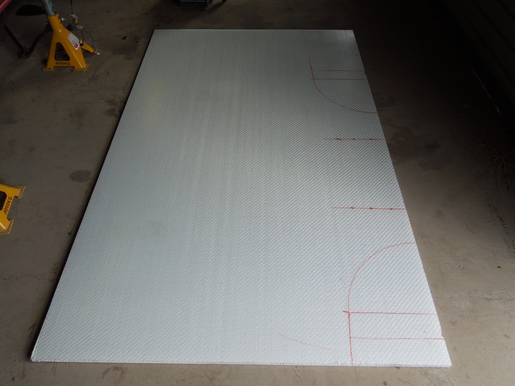
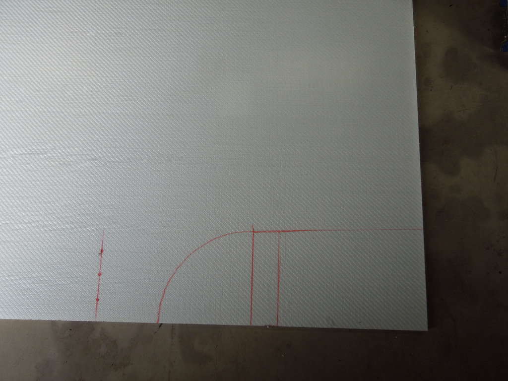
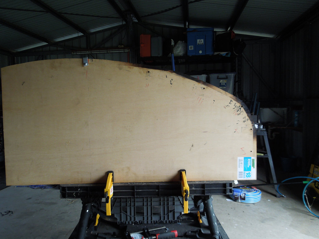
Cutting Plan. Made some changes to this version, an arch for the wheel turn radius.
 DSCN2606 by Eipeip, on Flickr
 DSCN2608 by Eipeip, on Flickr
Cut out (used an air panel saw, like a knife through butter)
 DSCN2616 by Eipeip, on Flickr
 DSCN2617 by Eipeip, on Flickr
 DSCN2610 by Eipeip, on Flickr
 DSCN2611 by Eipeip, on Flickr
 DSCN2619 by Eipeip, on Flickr
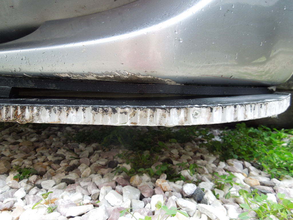
Close up of edge after a bit of a clean up. Started with a die grinder, not very effective. Then a 3" grinder that worked a treat. I used more clark rubber foam to fill up the air gap. A more permanent solution is needed, a work in progress. The gap is caused by the GV Lip not being perfectly flat/level.
 DSCN2626 by Eipeip, on Flickr
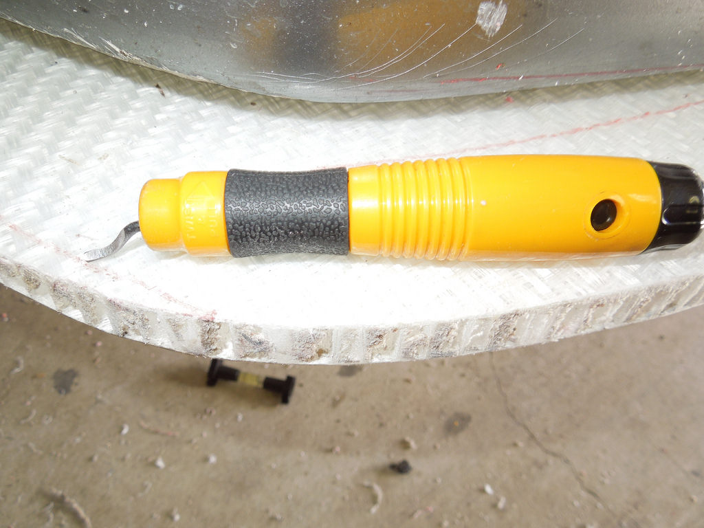
A great tool to clean up the edges after the grinder.
 DSCN2625 by Eipeip, on Flickr
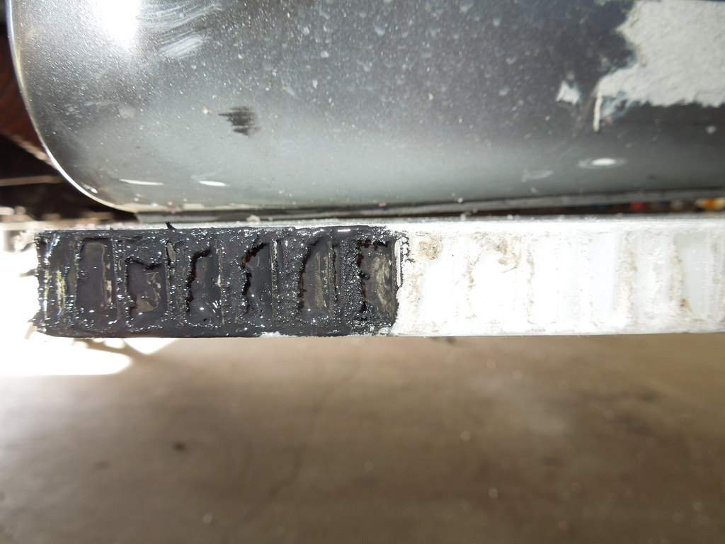
This is what the edge looks like close up with a bit of flat black paint.
 DSCN2624 by Eipeip, on Flickr
This is where it stayed for a few weeks, until I could do the edge protection. I attached some rubber seal from Clark Rubber to protect it a bit. Monopan does not hold very well to screws put into the honeycomb middle structure. Fastners need to go perpendicular to the surface not horizontal.
 DSCN2665 by Eipeip, on Flickr
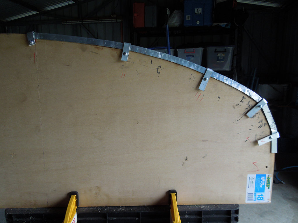
How to bend the aluminium U channel that I planned on using. After loots of attempts I got a sheet of 18mm marine ply and cut out 1/2 of the splitter. I also attached a few hold down points to help it keep its shape.
 DSCN2667 by Eipeip, on Flickr
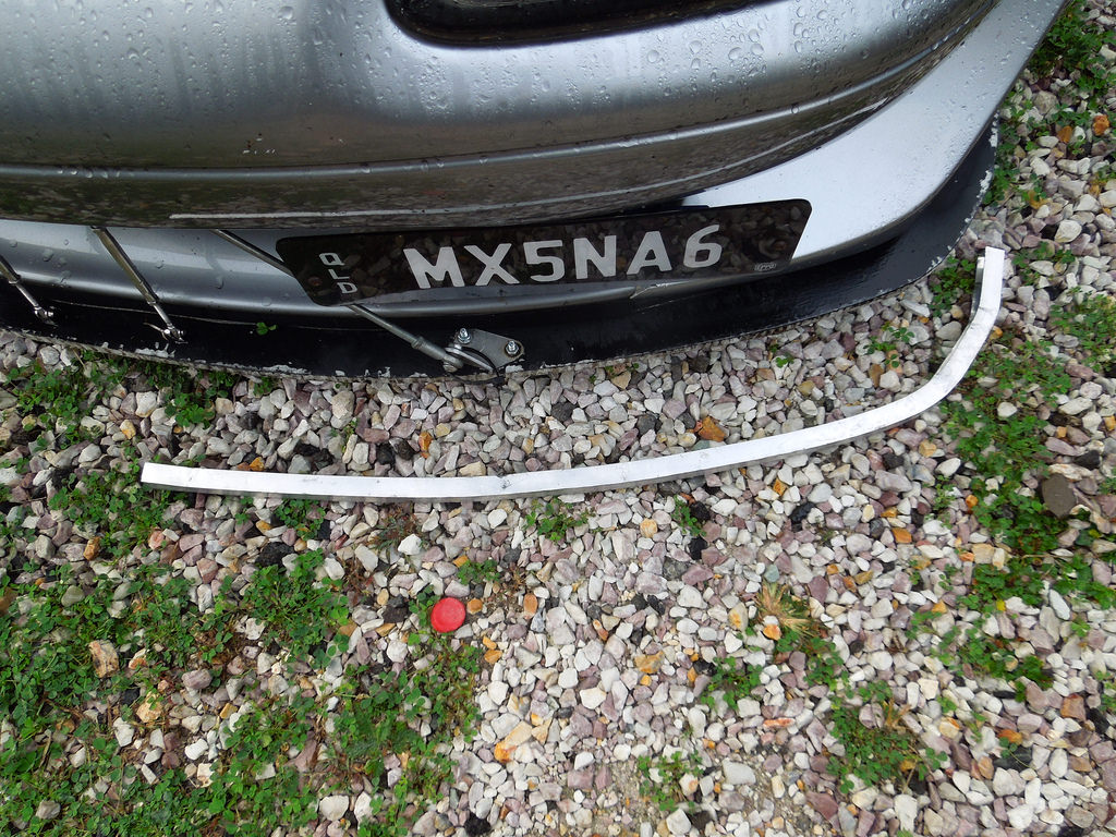
After heating the aluminium and 'tapping, it against the mould, a test piece.
 DSCN2669 by Eipeip, on Flickr
 DSCN2666 by Eipeip, on Flickr
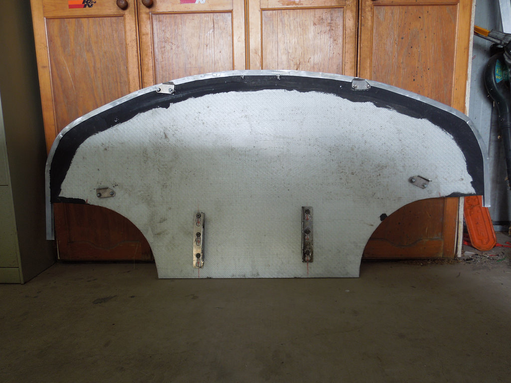
Final version. It is held on with Sikaflex and riveted from the underside. I would have preferred to use peel rivets however they are not available over the counter in my area.
 DSCN2675 by Eipeip, on Flickr
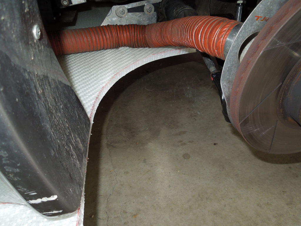
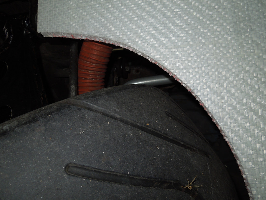
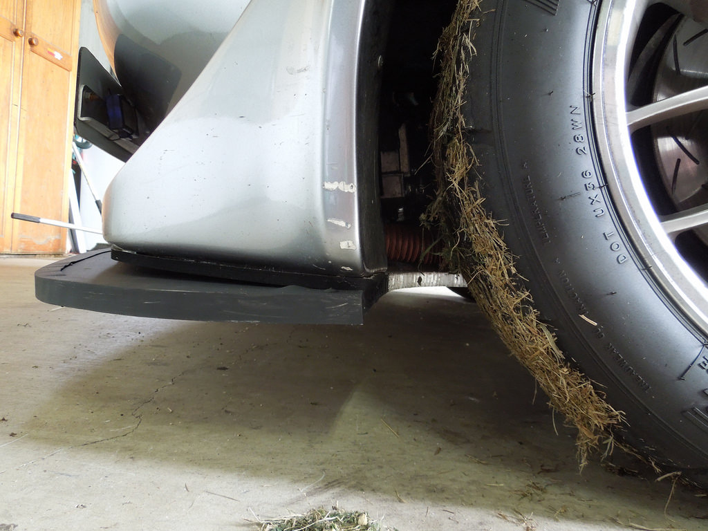
A closeup of the edge inside the wheel well. A nice neat fit.
 DSCN2676 by Eipeip, on Flickr
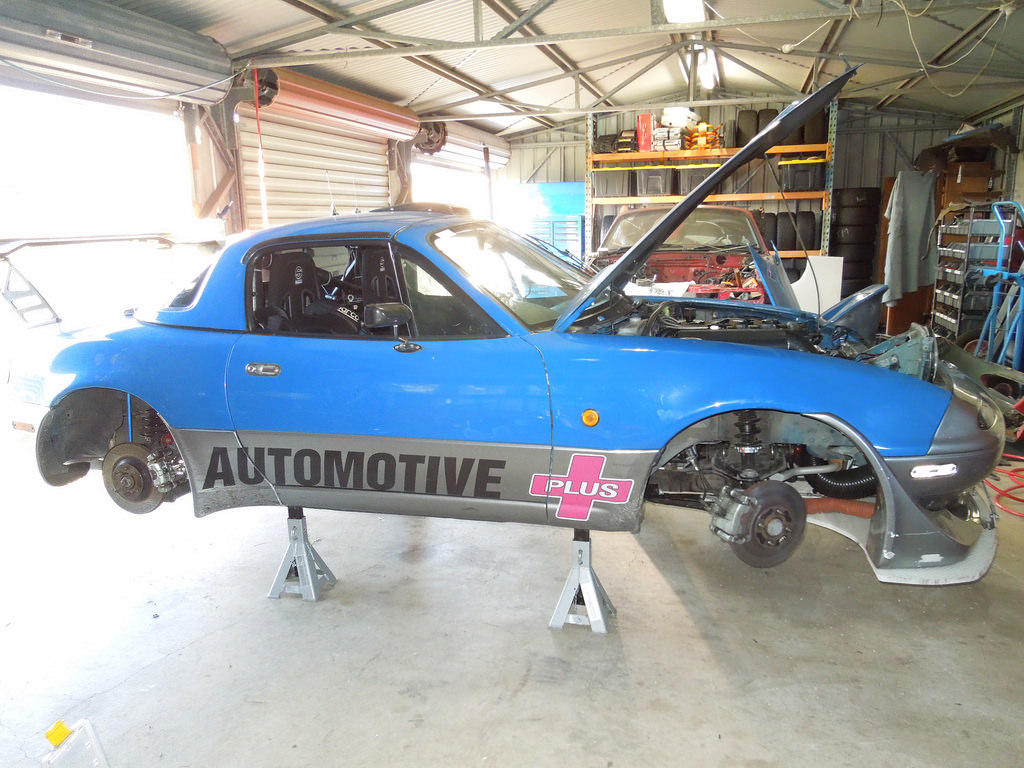
Finished
 DSCN2680 by Eipeip, on Flickr
 DSCN2679 by Eipeip, on Flickr
A few creases, I'll get better at shaping the aluminium, or sand it flat next time.
 DSCN2681 by Eipeip, on Flickr
Version 1 - 9.7 kg (ABS Plastic)
Version 2 - 7.2 kg was made from ply 10mm with 2 layers of fibreglass on the bottom and 1 on the top. It has lasted quite well to be honest.
Version 3 - 5 kg is made from 17mm Monopan Sandwich Panel ? MonoPan � Lavender CE Pty Ltd. This stuff is strong and light! However the edge does not take drilling too well. I'm getting some 1.6mm x 17mm U channel aluminium to put around the leading edge to protect it. Enough Monopan to make 2 splitters cost about $250. It is easy to cut but a bit painful to shape and trim. In the end I got an air angle grinder out and this worked well. Note this is also a bit bigger than the other 2 but weights LESS.
Version 3...
Monopan under the front after V2 splitter removed
DSCN2609 by Eipeip, on FlickrVersion 2 - after about 18 months of use.
DSCN2607 by Eipeip, on FlickrStarting to mark out (the red dot in the middle is in the flash shadow)
DSCN2613 by Eipeip, on FlickrDSCN2612 by Eipeip, on FlickrDSCN2615 by Eipeip, on FlickrCutting Plan. Made some changes to this version, an arch for the wheel turn radius.
DSCN2606 by Eipeip, on FlickrDSCN2608 by Eipeip, on FlickrCut out (used an air panel saw, like a knife through butter)
DSCN2616 by Eipeip, on FlickrDSCN2617 by Eipeip, on FlickrDSCN2610 by Eipeip, on FlickrDSCN2611 by Eipeip, on FlickrDSCN2619 by Eipeip, on FlickrClose up of edge after a bit of a clean up. Started with a die grinder, not very effective. Then a 3" grinder that worked a treat. I used more clark rubber foam to fill up the air gap. A more permanent solution is needed, a work in progress. The gap is caused by the GV Lip not being perfectly flat/level.
DSCN2626 by Eipeip, on FlickrA great tool to clean up the edges after the grinder.
DSCN2625 by Eipeip, on FlickrThis is what the edge looks like close up with a bit of flat black paint.
DSCN2624 by Eipeip, on FlickrThis is where it stayed for a few weeks, until I could do the edge protection. I attached some rubber seal from Clark Rubber to protect it a bit. Monopan does not hold very well to screws put into the honeycomb middle structure. Fastners need to go perpendicular to the surface not horizontal.
DSCN2665 by Eipeip, on FlickrHow to bend the aluminium U channel that I planned on using. After loots of attempts I got a sheet of 18mm marine ply and cut out 1/2 of the splitter. I also attached a few hold down points to help it keep its shape.
DSCN2667 by Eipeip, on FlickrAfter heating the aluminium and 'tapping, it against the mould, a test piece.
DSCN2669 by Eipeip, on FlickrDSCN2666 by Eipeip, on FlickrFinal version. It is held on with Sikaflex and riveted from the underside. I would have preferred to use peel rivets however they are not available over the counter in my area.
DSCN2675 by Eipeip, on FlickrA closeup of the edge inside the wheel well. A nice neat fit.
DSCN2676 by Eipeip, on FlickrFinished
DSCN2680 by Eipeip, on FlickrDSCN2679 by Eipeip, on FlickrA few creases, I'll get better at shaping the aluminium, or sand it flat next time.
DSCN2681 by Eipeip, on Flickr
Reply
0
0
 07-13-2015, 01:48 PM
#864
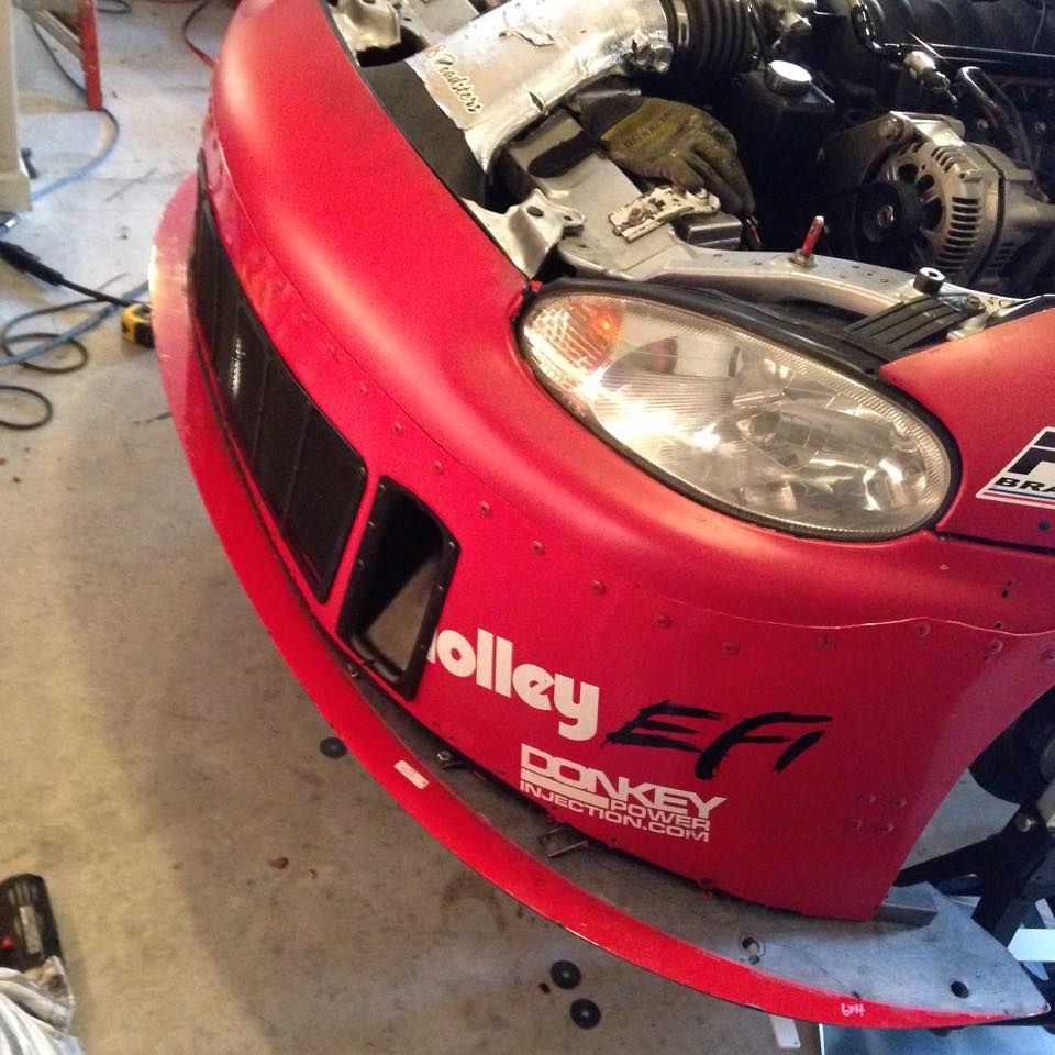
got this NASA splitter installed over the weekend. i remember someone telling me they won't fit.
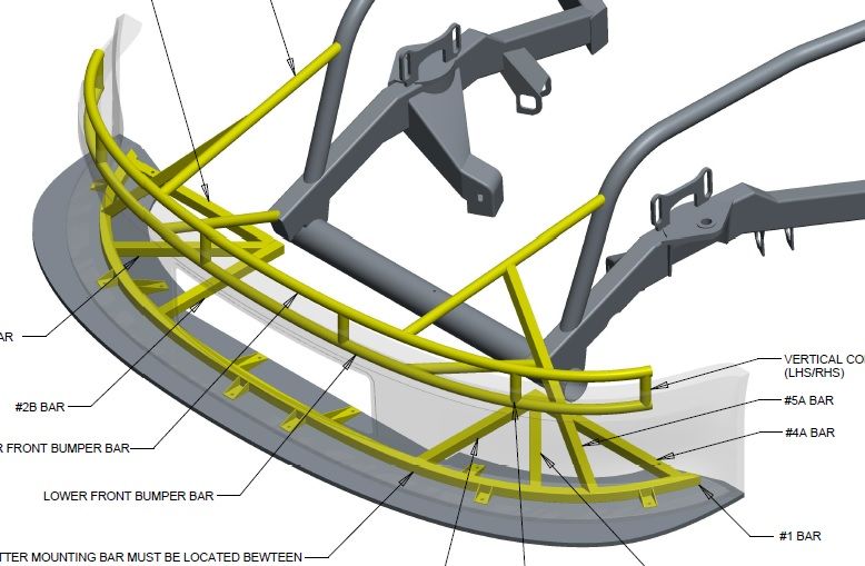
I got the diagram from a buddy that works in the nationwide series. used 1"x1" .083 wall square stock. thing came out beef i would say it's close to 20 lbs. but i could use it as a bumper.
I got the diagram from a buddy that works in the nationwide series. used 1"x1" .083 wall square stock. thing came out beef i would say it's close to 20 lbs. but i could use it as a bumper.
__________________
OG Racing
Your Source For Motorsports Safety Equipment
WWW.OGRACING.COM
800.934.9112
703.430.3303
info@ogracing.com
OG Racing
Your Source For Motorsports Safety Equipment
WWW.OGRACING.COM
800.934.9112
703.430.3303
info@ogracing.com
Reply
0
0
07-13-2015, 02:25 PM
#865
Supporting Vendor

iTrader: (3)

Join Date: Jul 2006
Location: San Diego
Posts: 3,303
Total Cats: 1,216
Johnny - looks like you're actually using at least a portion of the original NASCAR splitter frame?
Looks good. Obviously need to cut off the rear portion that extends into the wheel well, but don't trim any of the width down to make it narrower.
-Ryan
Looks good. Obviously need to cut off the rear portion that extends into the wheel well, but don't trim any of the width down to make it narrower.
-Ryan

Reply
0
0
07-13-2015, 05:17 PM
#867
I just started to coppy the original nascar diagram. i'll post more pictures when i can get the car on the ground. Also i found out this is a cup car splitter, the nation wide splitters are larger. next time i order one i'll get the nation wide option. i trimmed the wheel wells with a sawzaw.
__________________
OG Racing
Your Source For Motorsports Safety Equipment
WWW.OGRACING.COM
800.934.9112
703.430.3303
info@ogracing.com
OG Racing
Your Source For Motorsports Safety Equipment
WWW.OGRACING.COM
800.934.9112
703.430.3303
info@ogracing.com
Reply
0
0
07-13-2015, 05:25 PM
#868

I have used a similar material for another project. I drilled small holes around the mount area, injected them with epeoxy, and then drilled the final size hole after it dried. Held fasteners much better. Cost some weight though....
Then I realized that I could drill the hole I wanted, then put a small Allen wrench in a drill and used it to sweep out the honeycomb around the hole. Then I filled that area with epoxy and micro balloon. Made a super strong hole/mount area. Then I used carbon tube on the leading edges to close that. Again removing the honeycomb in the way, and epoxy the tube in place.
Then I realized that I could drill the hole I wanted, then put a small Allen wrench in a drill and used it to sweep out the honeycomb around the hole. Then I filled that area with epoxy and micro balloon. Made a super strong hole/mount area. Then I used carbon tube on the leading edges to close that. Again removing the honeycomb in the way, and epoxy the tube in place.
Last edited by ryansmoneypit; 07-13-2015 at 06:26 PM.
Reply
0
0
08-01-2015, 11:15 PM
#870
Supporting Vendor
iTrader: (3)
Join Date: Jul 2006
Location: San Diego
Posts: 3,303
Total Cats: 1,216
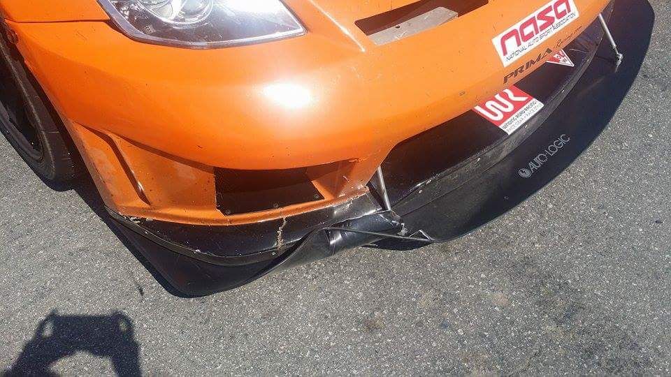
Random pic that popped up on my facebook. This was done by a cone. Aluminum splitter FTL. Birch splitter would have beheaded the cone, with nothing more than a smudge mark to show for it. I know, I've mowed down my fair share 
Reply
0
0
08-03-2015, 01:22 PM
#871
Senior Member
iTrader: (1)

Join Date: Dec 2008
Location: Manassas, Virginia
Posts: 1,242
Total Cats: 57
I really like all of these splitter/undertray projects. I'm already taking advice from this thread to make a splitter for my miata, but I was wondering if my daily driven RSX would benefit from it considering gas mileage predominantly (mostly interstate) and maybe a little handling? For the return on investment, would it be an all or nothing kind of thing? For instance would you need to make a splitter, full flat undertray, and diffuser to make it worth it or would a splitter that extends to about the front axle be worth the time and money?
Reply
0
0


 08-03-2015, 04:25 PM
#874
a quick update i ran road Atlanta. it was 15* hotter then when i ran before and almost matched my best time. 1.39.5 vs 1:39.2. i think the splitter is too high off the ground. i'm going to lower it one inch.
i didn't notice much difference in the butt dyno, according to my Aim Solo i still pulled a peak of 1.2G.
What i did notice was in the braking zone, holy molly i could get way more into the pedal. I was straining at the harness. that's what leads me to think it needs to get lower. i noticed it when it got close to the ground.
__________________
OG Racing
Your Source For Motorsports Safety Equipment
WWW.OGRACING.COM
800.934.9112
703.430.3303
info@ogracing.com
OG Racing
Your Source For Motorsports Safety Equipment
WWW.OGRACING.COM
800.934.9112
703.430.3303
info@ogracing.com
Reply
0
0
08-05-2015, 06:24 PM
#875
Elite Member

Join Date: Oct 2011
Location: OKC, OK
Posts: 3,693
Total Cats: 222
I really like all of these splitter/undertray projects. I'm already taking advice from this thread to make a splitter for my miata, but I was wondering if my daily driven RSX would benefit from it considering gas mileage predominantly (mostly interstate) and maybe a little handling? For the return on investment, would it be an all or nothing kind of thing? For instance would you need to make a splitter, full flat undertray, and diffuser to make it worth it or would a splitter that extends to about the front axle be worth the time and money?
Reply
0
0
 08-06-2015, 12:57 PM
#878
Elite Member
Join Date: Oct 2011
Location: OKC, OK
Posts: 3,693
Total Cats: 222
The BRZ has a relatively flat floor pan to begin with so.....no idea?
Reply
0
0
08-06-2015, 07:34 PM
#879
Senior Member
iTrader: (1)
Join Date: Dec 2008
Location: Manassas, Virginia
Posts: 1,242
Total Cats: 57

Reply
0
0


