Adaptronic Install Instructions for an NB
 03-19-2009, 08:25 PM
#1
Elite Member
Thread Starter
iTrader: (46)
Join Date: Dec 2007
Location: Nebraska
Posts: 4,729
Total Cats: 166
I wanted to document the installation of the Adaptronic in a NB Miata so that all don't have to go through the learing curve that I did.
There are a couple of things that you will need to install the Adaptronic in addition to the unit. You will need:
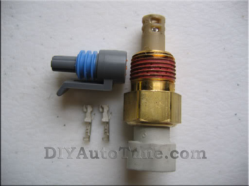
GM open sensor IAT
Wire to mount MAP and IAT
Soldering Iron
Two DB9 cables
DB9 to USB interface if your computer doesn't have a DB9 connection
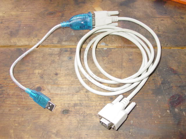
One of the DB9 cables will be used for tuning. The other will be hacked to make the serial interface between the Adaptronic and the WB. Here is what the cable and USB interface looks like.
IAT Installation:
Use a GM open sensor IAT. Mount it in the IC charge pipes after the intercooler as close to the throttle body as possible but try to kep it out of the engine bay to prevent heat soak. As my charge pipe routing goes through the fenders, I was able to mount it in front of the splash shield in front of the passenger front tire.
Cut off the factory IAT that pushes into the rubber grommet on the stock air box and wire the two leads to the GM IAT. I soldered them instead of crimp connectors. Polarity doesn't matter.
The IAT sensor has to be calibrated for every 5*C. I was fortunate to be doing my install when it was -15*C so I wired the IAT in, put it in a small sealed carboard box with a meat thermometer inserted in the box and was able to let the WARI program "learn" the cold temps. I then used a heat gun through a flap in the box to heat the air to 80*C, close up the box and use the WARI program to "learn" the temp every 5*C as the temps fell. I did this over two days to make sure that I didn't have any errors. You can do the same or copy my calibration table from my ECU file if you don't want to do your own.
Next you need to install your MAP sensor. There are three wires - a 5V+, ground and signal. Here is what the pinout looks like.
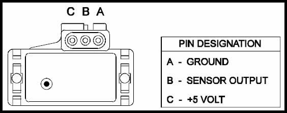
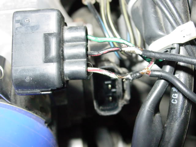
Use the 5V+ and ground from the TPS and the signal wire from the stock MAF. Cut off the MAF connector. Attach the signal wire (Orange) from the MAP to the green/black wire. Seal off the other two wires as they won't be used.
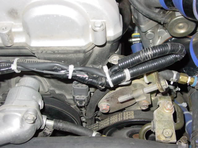
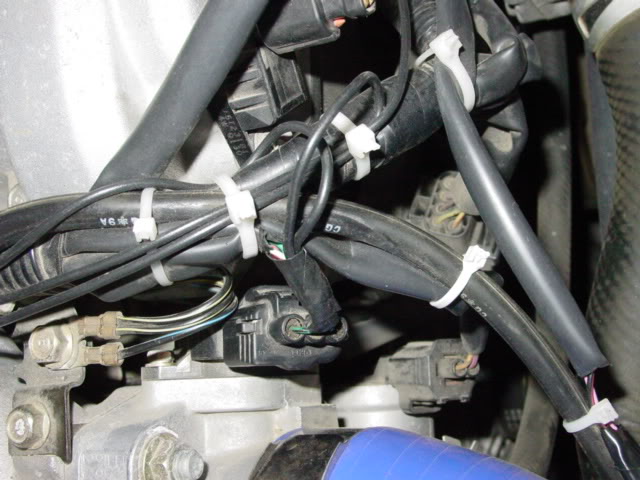
I folded the IAT lead back over itself on the harness, tucked away the unused wires and zip tied it to the main harness.
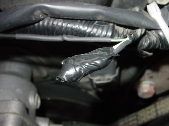
Power and ground come from the TPS. Strip back the insulation on the light green/red and solder on a wire for the lead to the +5V on the MAP(yellow). Strip back the insulation on the black/red and solder on the lead for the MAP ground (brown). Seal up and insulate the two wires so that they can't touch each other.
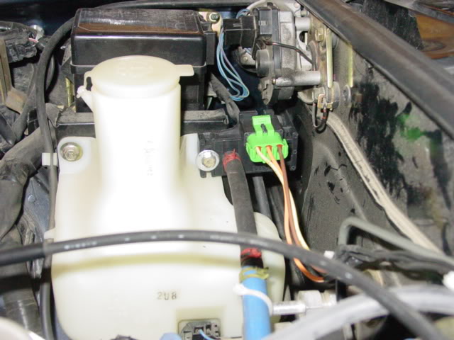
I mounted the MAP behind the windshield washer reservoir using one of the bolts to mount it. You have to use a longer bolt. This allows it to be secure, plus being close to the vacuum line that I tapped into.
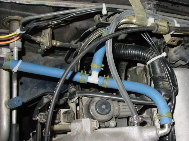
I used the brake booster line for my vacuum line. I replaced the line that goes from the rear port on the manifold with a 5/16" line that was left over from my water line install for the turbo. I added a 5/16" tee and a short section of 5/16" line, and then used a 5/16" to 1/4" reducer to get down to the 1/4" line needed to go into the MAP.
That's it under the hood.
Next you have to mount your WB according to manufacturer's instructions. I used an AEM UEGO. To connect to the Adaptronic you need a DB9 cable, female end only. Cut the end off the cable with another 12-18" of cable with it. Strip back the wires. You need to find out which colors are used on Pin 5 and Pin 2. Use a voltmeter to check continuity. Don't trust the color codes. My AEM manual said that they usually are red and green but mine were yellow and brown.
The AEM manual was a little unclear as to which pin was which. It is listed as "wire view" so it is opposite of the diagram when looking at the end of the female connector. Take a look at this picture.
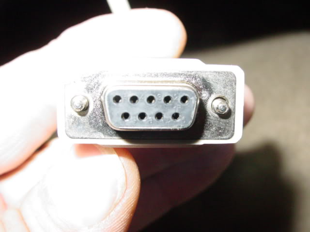
(Now that I reread this post, it seems that the pin numbers are molded in place on the connector as shown in the photo.) Pin 5 is the upper LEFT pin. Pin 2 is the 4th pin from the left in the top row. Probe the two pin holes to find which wire is Pin 2. That is your signal wire. Solder the BLUE wire from the AEM UEGO harness to this wire. Pin 5 is your ground wire. Solder a length of wire to this wire sufficiently long to reach a convenient chassis ground point. Ground this wire to the chassis. Mount the rest of the wideband according to the AEM directions.
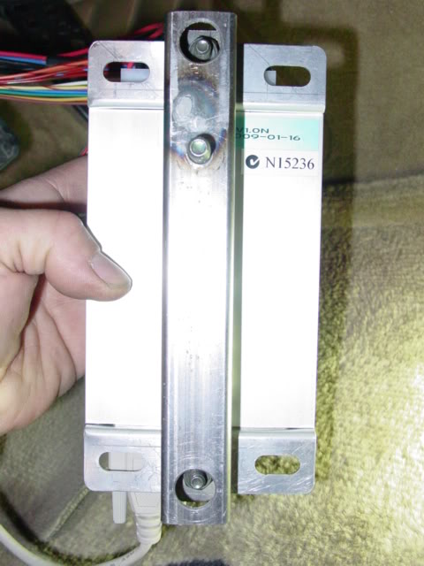
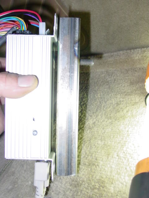
Next, figure out how you are going to mount the ECU. I found that there is a large flat bar under the dash to the right of the steering column that is perfect. Plenty of room and close enough that the Adaptronic harness will reach the stock ECU. I made a bracket to mount it. I used 1" square tubing to allow the bolts to be countersunk. The bolt through the tubing that mounts to the bracket under the dash was welded into the tubing so that it couldn't rotate. It made installing into the factory hole in the bracket a breeze.
After you are sure that everything fits properly, install the cables. Pull the three cables from the stock ECU. Plug in the three cables from the Adaptronic into the stock ECU and the stock ECU cables into the Adaptronic. Plug in the female DB9 cable that carries the WB into the Adaptronic. Plug in the other cable that you use for tuning into the Adaptronic. Mount the Adaptronic under the dash. Here it is installed in the car.
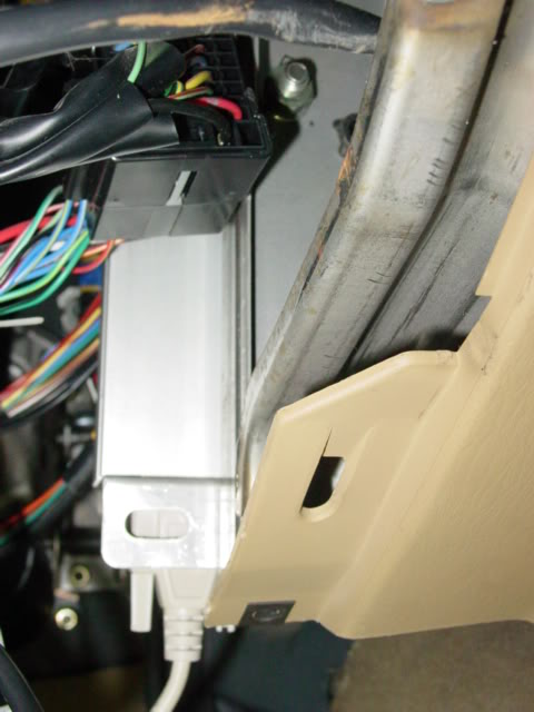
Ziptie all of the wires out of the way, along with the WB wires. If you mount it in the location detailed above, the tuning cable runs straight down along the transmission tunnel and doesn't get in your way while driving the car while tuning.
With the laptop hooked up, Open the WARI program and turn on the ignition. When it says ECU connected load the base map. It will take a minute or two. When it shows the tuning table all is loaded. The car should start on the base map, assuming you are on stock injectors.
There are a couple of things that you will need to install the Adaptronic in addition to the unit. You will need:
GM open sensor IAT
Wire to mount MAP and IAT
Soldering Iron
Two DB9 cables
DB9 to USB interface if your computer doesn't have a DB9 connection
One of the DB9 cables will be used for tuning. The other will be hacked to make the serial interface between the Adaptronic and the WB. Here is what the cable and USB interface looks like.
IAT Installation:
Use a GM open sensor IAT. Mount it in the IC charge pipes after the intercooler as close to the throttle body as possible but try to kep it out of the engine bay to prevent heat soak. As my charge pipe routing goes through the fenders, I was able to mount it in front of the splash shield in front of the passenger front tire.
Cut off the factory IAT that pushes into the rubber grommet on the stock air box and wire the two leads to the GM IAT. I soldered them instead of crimp connectors. Polarity doesn't matter.
The IAT sensor has to be calibrated for every 5*C. I was fortunate to be doing my install when it was -15*C so I wired the IAT in, put it in a small sealed carboard box with a meat thermometer inserted in the box and was able to let the WARI program "learn" the cold temps. I then used a heat gun through a flap in the box to heat the air to 80*C, close up the box and use the WARI program to "learn" the temp every 5*C as the temps fell. I did this over two days to make sure that I didn't have any errors. You can do the same or copy my calibration table from my ECU file if you don't want to do your own.
Next you need to install your MAP sensor. There are three wires - a 5V+, ground and signal. Here is what the pinout looks like.
Use the 5V+ and ground from the TPS and the signal wire from the stock MAF. Cut off the MAF connector. Attach the signal wire (Orange) from the MAP to the green/black wire. Seal off the other two wires as they won't be used.
I folded the IAT lead back over itself on the harness, tucked away the unused wires and zip tied it to the main harness.
Power and ground come from the TPS. Strip back the insulation on the light green/red and solder on a wire for the lead to the +5V on the MAP(yellow). Strip back the insulation on the black/red and solder on the lead for the MAP ground (brown). Seal up and insulate the two wires so that they can't touch each other.
I mounted the MAP behind the windshield washer reservoir using one of the bolts to mount it. You have to use a longer bolt. This allows it to be secure, plus being close to the vacuum line that I tapped into.
I used the brake booster line for my vacuum line. I replaced the line that goes from the rear port on the manifold with a 5/16" line that was left over from my water line install for the turbo. I added a 5/16" tee and a short section of 5/16" line, and then used a 5/16" to 1/4" reducer to get down to the 1/4" line needed to go into the MAP.
That's it under the hood.
Next you have to mount your WB according to manufacturer's instructions. I used an AEM UEGO. To connect to the Adaptronic you need a DB9 cable, female end only. Cut the end off the cable with another 12-18" of cable with it. Strip back the wires. You need to find out which colors are used on Pin 5 and Pin 2. Use a voltmeter to check continuity. Don't trust the color codes. My AEM manual said that they usually are red and green but mine were yellow and brown.
The AEM manual was a little unclear as to which pin was which. It is listed as "wire view" so it is opposite of the diagram when looking at the end of the female connector. Take a look at this picture.
(Now that I reread this post, it seems that the pin numbers are molded in place on the connector as shown in the photo.) Pin 5 is the upper LEFT pin. Pin 2 is the 4th pin from the left in the top row. Probe the two pin holes to find which wire is Pin 2. That is your signal wire. Solder the BLUE wire from the AEM UEGO harness to this wire. Pin 5 is your ground wire. Solder a length of wire to this wire sufficiently long to reach a convenient chassis ground point. Ground this wire to the chassis. Mount the rest of the wideband according to the AEM directions.
Next, figure out how you are going to mount the ECU. I found that there is a large flat bar under the dash to the right of the steering column that is perfect. Plenty of room and close enough that the Adaptronic harness will reach the stock ECU. I made a bracket to mount it. I used 1" square tubing to allow the bolts to be countersunk. The bolt through the tubing that mounts to the bracket under the dash was welded into the tubing so that it couldn't rotate. It made installing into the factory hole in the bracket a breeze.
After you are sure that everything fits properly, install the cables. Pull the three cables from the stock ECU. Plug in the three cables from the Adaptronic into the stock ECU and the stock ECU cables into the Adaptronic. Plug in the female DB9 cable that carries the WB into the Adaptronic. Plug in the other cable that you use for tuning into the Adaptronic. Mount the Adaptronic under the dash. Here it is installed in the car.
Ziptie all of the wires out of the way, along with the WB wires. If you mount it in the location detailed above, the tuning cable runs straight down along the transmission tunnel and doesn't get in your way while driving the car while tuning.
With the laptop hooked up, Open the WARI program and turn on the ignition. When it says ECU connected load the base map. It will take a minute or two. When it shows the tuning table all is loaded. The car should start on the base map, assuming you are on stock injectors.
Last edited by Stein; 03-19-2009 at 09:03 PM.

Reply
 0
0

0


 03-19-2009, 11:04 PM
#5
Elite Member
iTrader: (22)

Join Date: Dec 2006
Location: Sunny Spanish speaking Non US Caribbean
Posts: 3,224
Total Cats: 3
Many thanks Stein 
I suggestion: can you follow it up by giving us your first impressions about the Adaptronic in every day driving. Such as:
- How is your idle?
- Have you faced any cranking issues?
- How is the autotune feature?
I suggestion: can you follow it up by giving us your first impressions about the Adaptronic in every day driving. Such as:
- How is your idle?
- Have you faced any cranking issues?
- How is the autotune feature?
Reply
0
0
03-19-2009, 11:14 PM
#6
Elite Member
Thread Starter
iTrader: (46)
Join Date: Dec 2007
Location: Nebraska
Posts: 4,729
Total Cats: 166
Autotune is seamless and completely awesome. I rapid tuned for two days and slow converge tuned the last two days. Hitting target AFR nicely now. It's idiot proof.
It keeps getting better each day. As soon as the first person needs a stock injector base map, I'll post it. The longer I wait the better the base tune will be. The map is scaleable by percentage, so if one has bigger injectors they can load the base map and scale it up. They will have to idle tune by hand as I did. but the scaled map will get them going and it will autotune the rest.
I'm still running on the supplied base map for spark. When I feel the fuel map is tuned, I'll let it auto tune the spark, but I haven't noticed any problems with the base ignition map so far with a hundred full boosted runs.
I can't believe that it is this easy, but it really is.
Reply
0
0


 03-20-2009, 12:02 PM
#13
Elite Member
Thread Starter
iTrader: (46)
Join Date: Dec 2007
Location: Nebraska
Posts: 4,729
Total Cats: 166
Looking for 460's or 550's.
Reply
0
0
 03-21-2009, 10:49 AM
#20
Elite Member
Thread Starter
iTrader: (46)
Join Date: Dec 2007
Location: Nebraska
Posts: 4,729
Total Cats: 166
Here is the one I bought:
MegaSquirtPNP IAT Sensor Kit - Steel Bung DIYAutoTune.com
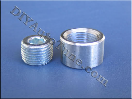
It is open element, came with enough wire to make the connection and the pins, plus a steel bung to weld into the charge pipe.
If you have aluminum pipes, you will need this one to get the aluminum bung to weld in:
MegaSquirtPNP IAT Sensor Kit - Aluminum Bung DIYAutoTune.com
It's cheaper than ordering parts separately.
Steel bung in steel pipes, aluminum bung in aluminum pipes.
MegaSquirtPNP IAT Sensor Kit - Steel Bung DIYAutoTune.com
It is open element, came with enough wire to make the connection and the pins, plus a steel bung to weld into the charge pipe.
If you have aluminum pipes, you will need this one to get the aluminum bung to weld in:
MegaSquirtPNP IAT Sensor Kit - Aluminum Bung DIYAutoTune.com
It's cheaper than ordering parts separately.
Steel bung in steel pipes, aluminum bung in aluminum pipes.
Reply
0
0


