Transient Throttle
 02-18-2010, 12:05 PM
#41
Newb

Join Date: Jan 2010
Posts: 7
Total Cats: 0
This was on the adaptronic forum, might be of some help:
YouTube Link
The only difference to most settings seem to be the enrichment percentage which is set to 150%. The car is a stock miata btw. Have to wonder if its only good for n/a models as atmospheric "boost" is instant, whereas real boost will take a a certain length of time to build. I would imagine you would hit 100kpa very quickly and then from there to your positive boost is going to take a while longer which could account for the rich-lean-normal AFRs people are seeing with this.

Reply
 0
0

0
02-18-2010, 11:44 PM
#42
Junior Member

Join Date: Jan 2008
Location: Central, NJ
Posts: 200
Total Cats: 0
Thanks for the link. I fixed much of my lean tip in this week by lowering my spark plug gap to .035. It was left at the stock gap since I installed them a month before the turbo install. noob mistake... Now I have to lower the predicted map to where it should be and hopefully it won't lean back out.
Reply
0
0

 02-19-2010, 08:15 AM
#44

Thanks for the link. I fixed much of my lean tip in this week by lowering my spark plug gap to .035. It was left at the stock gap since I installed them a month before the turbo install. noob mistake... Now I have to lower the predicted map to where it should be and hopefully it won't lean back out.
Isn't the standard spec 0.030" ? How does spark plug gap affect afr conditions - bigger gap = lower afr?
Reply
0
0
02-19-2010, 10:15 AM
#45
2 Props,3 Dildos,& 1 Cat


iTrader: (8)
Join Date: Jun 2005
Location: Fake Virginia
Posts: 19,338
Total Cats: 573
saw the thread on the adaptronic forums suggesting that now instead of suggesting the async gain should be set to 150% as a default. prior to that it was 100%. and prior to that there were posts suggesting like 30-50%!
Reply
0
0
 02-19-2010, 07:13 PM
#48
Junior Member
Join Date: Jan 2008
Location: Central, NJ
Posts: 200
Total Cats: 0
I thought it was .040. I might still have to bring it down to .030. The AFR completely changed after changing the gap. At lower map it slightly leaned out some sections and at higher map it became too rich (partly due to the conservative predicted map). I still haven't changed to ve tuning though. I'm not sure how much of an affect that would have.
Reply
0
0
 04-03-2010, 09:56 AM
#53
Elite Member
iTrader: (15)

Join Date: Dec 2007
Location: San Antonio, Texas
Posts: 4,847
Total Cats: 27
I have a question/point based on watching the youtube video and a little lightbulb gong off in my head...
The whole point of all this is to compensate for delays in the MAP sensor response. Makes sense to me. The MAP value lags the actual condition in the manifold and thus this feature compensates by momentarily applying a table based 'predicted' MAP value, increasing fuel flow and improving throttle response. Great idea. It is significant to 'accelerator pump' style enrichment, except more sophisticated.
Question: So, where is that MAP response delay coming from in the first place? It should not be the electronics in the MAP, or anything in the Adaptronic. Both should respond instantaneously, relatively speaking. Therefore the delay, I suspect, is mostly due to the mechanics of the transient gas flows. That is, system characteristics like the air volume between the manifold and the MAP, the volume in the MAP, and the flow resistance in the vacuum line, are creating the delay. It is the same reason why the BOV line should be short and unrestricted; the BOV responds faster. These delays would seem to be trivial, but they are most certainly there (basic fluid dynamics) and we are only talking about milliseconds of lag here.
So here is my point. Perhaps one of the reasons everyone here (and on the Adaptronic board) is coming up with different settings is because everyone has slight differences in their MAP installations that change the volume and the flow resistance. Different line diameters, different lengths, where it is teed into the manifold, what else it teed into the same connection point, etc. would all change the behavior. They create variations in the transient response profile, and thus require different settings to compensate properly.
One thing to try might be to have a dedicated and very short vacuum line to the intake manifold. Minimize the line volume/length so that it becomes insignificant (using a very small diameter line could be problematic though since it would create flow resistance. A really short line would be better IMO). This would minimize the magnitude of the MAP delay, and thus minimize the amount of correction required. In turn, since the correction is minimized, then the criticality of having it exactly right would also be reduced, and thus it should be easier to tune.
Now I know there is also the transient response of the intake manifold volume to consider as well. But, loosely speaking here, the pressure at the end of the runner should be very closely tied to this response, and in that sense it really is the same actual condition.
Makes sense?
Last edited by ZX-Tex; 04-03-2010 at 10:06 AM.
Reply
0
0
04-03-2010, 01:14 PM
#54
Elite Member
Thread Starter
iTrader: (9)

Join Date: Jun 2008
Location: Houston, TX
Posts: 1,547
Total Cats: 13
I have a question/point based on watching the youtube video and a little lightbulb gong off in my head...
The whole point of all this is to compensate for delays in the MAP sensor response. Makes sense to me. The MAP value lags the actual condition in the manifold and thus this feature compensates by momentarily applying a table based 'predicted' MAP value, increasing fuel flow and improving throttle response. Great idea. It is significant to 'accelerator pump' style enrichment, except more sophisticated.
Question: So, where is that MAP response delay coming from in the first place? It should not be the electronics in the MAP, or anything in the Adaptronic. Both should respond instantaneously, relatively speaking. Therefore the delay, I suspect, is mostly due to the mechanics of the transient gas flows. That is, system characteristics like the air volume between the manifold and the MAP, the volume in the MAP, and the flow resistance in the vacuum line, are creating the delay. It is the same reason why the BOV line should be short and unrestricted; the BOV responds faster. These delays would seem to be trivial, but they are most certainly there (basic fluid dynamics) and we are only talking about milliseconds of lag here.
So here is my point. Perhaps one of the reasons everyone here (and on the Adaptronic board) is coming up with different settings is because everyone has slight differences in their MAP installations that change the volume and the flow resistance. Different line diameters, different lengths, where it is teed into the manifold, what else it teed into the same connection point, etc. would all change the behavior. They create variations in the transient response profile, and thus require different settings to compensate properly.
One thing to try might be to have a dedicated and very short vacuum line to the intake manifold. Minimize the line volume/length so that it becomes insignificant (using a very small diameter line could be problematic though since it would create flow resistance. A really short line would be better IMO). This would minimize the magnitude of the MAP delay, and thus minimize the amount of correction required. In turn, since the correction is minimized, then the criticality of having it exactly right would also be reduced, and thus it should be easier to tune.
Now I know there is also the transient response of the intake manifold volume to consider as well. But, loosely speaking here, the pressure at the end of the runner should be very closely tied to this response, and in that sense it really is the same actual condition.
Makes sense?
The whole point of all this is to compensate for delays in the MAP sensor response. Makes sense to me. The MAP value lags the actual condition in the manifold and thus this feature compensates by momentarily applying a table based 'predicted' MAP value, increasing fuel flow and improving throttle response. Great idea. It is significant to 'accelerator pump' style enrichment, except more sophisticated.
Question: So, where is that MAP response delay coming from in the first place? It should not be the electronics in the MAP, or anything in the Adaptronic. Both should respond instantaneously, relatively speaking. Therefore the delay, I suspect, is mostly due to the mechanics of the transient gas flows. That is, system characteristics like the air volume between the manifold and the MAP, the volume in the MAP, and the flow resistance in the vacuum line, are creating the delay. It is the same reason why the BOV line should be short and unrestricted; the BOV responds faster. These delays would seem to be trivial, but they are most certainly there (basic fluid dynamics) and we are only talking about milliseconds of lag here.
So here is my point. Perhaps one of the reasons everyone here (and on the Adaptronic board) is coming up with different settings is because everyone has slight differences in their MAP installations that change the volume and the flow resistance. Different line diameters, different lengths, where it is teed into the manifold, what else it teed into the same connection point, etc. would all change the behavior. They create variations in the transient response profile, and thus require different settings to compensate properly.
One thing to try might be to have a dedicated and very short vacuum line to the intake manifold. Minimize the line volume/length so that it becomes insignificant (using a very small diameter line could be problematic though since it would create flow resistance. A really short line would be better IMO). This would minimize the magnitude of the MAP delay, and thus minimize the amount of correction required. In turn, since the correction is minimized, then the criticality of having it exactly right would also be reduced, and thus it should be easier to tune.
Now I know there is also the transient response of the intake manifold volume to consider as well. But, loosely speaking here, the pressure at the end of the runner should be very closely tied to this response, and in that sense it really is the same actual condition.
Makes sense?
Yea makes sense. Although I believe the majority of the delay is electronically induced. The speed of sound would be 1125 ft/s in semi normal conditions of the manifold, and so at 200ms delay that some people use would be 225 feet worth of travel. The actual time it takes the plenum and the runners to pressurize should be around 1ms (2ft).
What they are trying to do with an electronic delay is to mitigate the pulses caused by the cylinders and get an average plenum reading that correlates more with throttle position and cylinder filling.
The rubber hoses might have more significant effects though because it does dampen pulses due to its elastic cross section, and its fairly small area to volume ratio. From a speed of sound point of view we're talking 1 ms per 2 feet of hose. Even if it takes twice that long or 4 times that long to fill the tube the change is pretty nugatory compared to the delay and setting differences we're seeing.
What I attribute to the differences comes from all the other variables that change the dynamic reaction of the motor. Camshafts, turbochargers, headwork, intake manifolds, throttle bodies, intake tubing, helmoholtz resonators, even headers to some extent(reversion, scavaging... etc).
So as you change all these things the instantaneous fuel demands will change, and the calculations to figure out what it should be based on a difference of any of the variables above would probably earn you a Nobel prize in fluid dynamics.
Regardless of all this crap, I have thought about standardizing the install process more. Providing tubing for the map, and an exact place for everyone to mount it. Elimination of variables is the first step to making this transient tip in tuning a more standardized process and I am right there with you on knocking a few more of the variables out so we can concentrate on just the differences in engines and not have to worry about these secondary variables that can be all over the map.
Reply
0
0
04-03-2010, 10:52 PM
#55
Elite Member
iTrader: (15)
Join Date: Dec 2007
Location: San Antonio, Texas
Posts: 4,847
Total Cats: 27
Yes I thought about it some more today and agree that the delay in the MAP pressure drop is probably just one of many dynamics leading to the measured delay.
One thing though, and no offense Travis, but I do not agree with the part about how the pressure signal travels at the speed of sound. For pressure to drop in a volume (constant volume, constant temp) the air has to be evacuated from the volume via flow. So I do not think one can conclude that the MAP signal response happens as fast as you described.
Think of it this way. Allow me to illustrate by extremes. Say I have a large volume (manifold) connected to a small volume (MAP sensor) with a hose. The pressure in both volumes and the connecting hose are all equal (steady-state pressure).
Now, think of two different experiments that use two different size interconnecting hoses. One is large, say 3/8" i.d. and one is small, say 1/8" i.d.. Everything else stays the same (volume sizes, and hose length). For this illustration assume the volume of the hoses is relatively negligible.
- Test #1, Connect the two volumes with the large hose. Suddenly raise the pressure in the larger volume (open the throttle), and measure (versus time) the relative pressure difference between the large volume and small volume. The pressure rise in the small volume will slightly lag the pressure rise in the large volume.
- Test #2, do everything the same as Test #1 but replace the large hose with the small one. The pressure rise in the small volume will lag farther behind the large volume than it did with Test #1. There is significantly more flow restriction with the smaller diameter hose and therefore the small volume does not pressurize as quickly, and the pressure lags farther behind.
This is illustrated by the fact that a small restrictor in the MAP vacuum line can be used to make a MAP sensor (or a vacuum gauge) have a quieter (less noisy) response. The restriction slows down the flow between the manifold and the MAP sensor (increasing the lag time) and thus dampens out the small transients from the intake pulses. Same deal.
Last edited by ZX-Tex; 04-04-2010 at 03:40 PM.
Reply
0
0
04-04-2010, 10:32 PM
#56
Elite Member
Thread Starter
iTrader: (9)
Join Date: Jun 2008
Location: Houston, TX
Posts: 1,547
Total Cats: 13
I agree, my idea about pressure moving at the speed of sound is pretty dramatic, but all I was getting at is if pressure movement was limited by cross section versus volume problems then even if it takes it 5 or 10X the time that it would take the speed of sound, the difference still would not compensate for the delay times we have to use in the transient throttle system.
I have also heard of this system you were talking about with long vacuum tubes being used to dampen pulses. For instance in ITB systems I've heard that its pretty advantageous to equip the car with 30-40 inches of vacuum hose that is coiled up because generally you only connect to one cylinder and using such a long length of hose deadens in the pulses from the cylinder that are more evident in an ITB system. So I know for a fact you're spot on, but I've never done the experimental to know the exact time delay per foot of hose(if its even linear like that).
I have also heard of this system you were talking about with long vacuum tubes being used to dampen pulses. For instance in ITB systems I've heard that its pretty advantageous to equip the car with 30-40 inches of vacuum hose that is coiled up because generally you only connect to one cylinder and using such a long length of hose deadens in the pulses from the cylinder that are more evident in an ITB system. So I know for a fact you're spot on, but I've never done the experimental to know the exact time delay per foot of hose(if its even linear like that).
Yes I thought about it some more today and agree that the delay in the MAP pressure drop is probably just one of many dynamics leading to the measured delay.
One thing though, and no offense Travis, but I do not agree with the part about how the pressure signal travels at the speed of sound. For pressure to drop in a volume (constant volume, constant temp) the air has to be evacuated from the volume via flow. So I do not think one can conclude that the MAP signal response happens as fast as you described.
Think of it this way. Allow me to illustrate by extremes. Say I have a large volume (manifold) connected to a small volume (MAP sensor) with a hose. The pressure in both volumes and the connecting hose are all equal (steady-state pressure).
Now, think of two different experiments that use two different size interconnecting hoses. One is large, say 3/8" i.d. and one is small, say 1/8" i.d.. Everything else stays the same (volume sizes, and hose length). For this illustration assume the volume of the hoses is relatively negligible.
- Test #1, Connect the two volumes with the large hose. Suddenly raise the pressure in the larger volume (open the throttle), and measure (versus time) the relative pressure difference between the large volume and small volume. The pressure rise in the small volume will slightly lag the pressure rise in the large volume.
- Test #2, do everything the same as Test #1 but replace the large hose with the small one. The pressure rise in the small volume will lag farther behind the large volume than it did with Test #1. There is significantly more flow restriction with the smaller diameter hose and therefore the small volume does not pressurize as quickly, and the pressure lags farther behind.
This is illustrated by the fact that a small restrictor in the MAP vacuum line can be used to make a MAP sensor (or a vacuum gauge) have a quieter (less noisy) response. The restriction slows down the flow between the manifold and the MAP sensor (increasing the lag time) and thus dampens out the small transients from the intake pulses. Same deal.
One thing though, and no offense Travis, but I do not agree with the part about how the pressure signal travels at the speed of sound. For pressure to drop in a volume (constant volume, constant temp) the air has to be evacuated from the volume via flow. So I do not think one can conclude that the MAP signal response happens as fast as you described.
Think of it this way. Allow me to illustrate by extremes. Say I have a large volume (manifold) connected to a small volume (MAP sensor) with a hose. The pressure in both volumes and the connecting hose are all equal (steady-state pressure).
Now, think of two different experiments that use two different size interconnecting hoses. One is large, say 3/8" i.d. and one is small, say 1/8" i.d.. Everything else stays the same (volume sizes, and hose length). For this illustration assume the volume of the hoses is relatively negligible.
- Test #1, Connect the two volumes with the large hose. Suddenly raise the pressure in the larger volume (open the throttle), and measure (versus time) the relative pressure difference between the large volume and small volume. The pressure rise in the small volume will slightly lag the pressure rise in the large volume.
- Test #2, do everything the same as Test #1 but replace the large hose with the small one. The pressure rise in the small volume will lag farther behind the large volume than it did with Test #1. There is significantly more flow restriction with the smaller diameter hose and therefore the small volume does not pressurize as quickly, and the pressure lags farther behind.
This is illustrated by the fact that a small restrictor in the MAP vacuum line can be used to make a MAP sensor (or a vacuum gauge) have a quieter (less noisy) response. The restriction slows down the flow between the manifold and the MAP sensor (increasing the lag time) and thus dampens out the small transients from the intake pulses. Same deal.
Reply
0
0
06-14-2010, 10:13 AM
#57
Elite Member
iTrader: (15)
Join Date: Dec 2007
Location: San Antonio, Texas
Posts: 4,847
Total Cats: 27
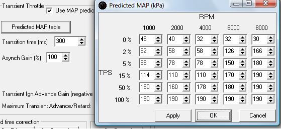
OK so I finally started playing around with Predicted MAP and it is working for me. I logged some drives, did some spreadsheet analysis (Openoffice calc), and plugged best-guess values into the table. I am really pleased so far. 100% gain, 300 ms.
This is a freshly rebuilt motor so my wastegate is wired open right now until I get everything dialed in. There is no boost except at very high RPMs. Point being that there is no point in posting my table because it will be wrong for most others, and I will be retuning it when the wastegate actuator is reconnected.
This is a freshly rebuilt motor so my wastegate is wired open right now until I get everything dialed in. There is no boost except at very high RPMs. Point being that there is no point in posting my table because it will be wrong for most others, and I will be retuning it when the wastegate actuator is reconnected.
Reply
0
0
07-17-2010, 09:44 PM
#58
Senior Member
iTrader: (3)

Join Date: Dec 2007
Location: Seven Valleys, PA
Posts: 638
Total Cats: 11
has anyone had any luck with this? i am having a hard time with getting transient throttle response in the low rpm 5% range and pretty much all transient throttle above 5000 rpm
Reply
0
0
07-22-2010, 10:09 AM
#60
2 Props,3 Dildos,& 1 Cat
iTrader: (8)
Join Date: Jun 2005
Location: Fake Virginia
Posts: 19,338
Total Cats: 573
I switched back to the non-predicted MAP method and I think I like it better. For one, you can set separate enrichments for MAP and TPS... because sometimes MAP increases without TPS increasing.
Reply
0
0


