GM boost control wiring question...
 06-21-2009, 12:51 AM
#1
Senior Member
Thread Starter
iTrader: (3)

Join Date: Apr 2006
Location: Northern Michigan
Posts: 900
Total Cats: 0
I replaced my manual boost controller with a GM boost controller and wired it to the TEN and +B terminals on the diagnostic box. But the EMS freaked out and error'd out, not even connecting. 
I am thinking about running one wire to 12V switched and the other wire to 2H on the EMS. Is this OK?
I am thinking about running one wire to 12V switched and the other wire to 2H on the EMS. Is this OK?

Reply
 0
0

0
 06-27-2009, 02:17 AM
#3
OK I reread your post, it is obviously a wiring problem, not the hoses.
The boost control needs switched 12 V and PW2 output. The output for PW2 (pulse width 2) is pin 2H as you said. This pin should connect to the TEN terminal at your diagnostic connector. Running another wire to the ECU would not change anything. The wire is light green/yellow.
From the manual:
"The AEM EMS has a very comprehensive and flexible boost control circuit. Using a pulse width actuated solenoid, boost can be controlled by vehicle speed, throttle position against rpm, and a switch input for low and high settings. At this time, AEM recommends the 3-way GM solenoid (PN 1997152).
The first thing to do is determine what frequency at which the solenoid needs to be operated. This information is typically provided by the manufacturer of the part. If you are using a plug n' play with a factory boost control solenoid, this comes pre-configured by AEM.
The PW# 2 output pin needs to be determined when installing a boost solenoid. Refer to the Application Notes for the pinouts of the specific EMS used. This information can also be found on the AEM EMS forum (Offical AEM Air Induction Systems and Performance Electronics Site - Home Page). There are two wire connections for a boost solenoid and there is no polarity. One wire connects to 12 volt switched power and the other will connect to the PW #2 output on the EMS."
My setup:
Boost W/G output: checked
Boost W/G frequency: 31 Hz
Boost/Idle PW TPS: 10%
Boost Duty Max: 85.16%
Boost Duty Min: 10.16%
Fuel Cut Load: 22.03 PSIg
Good Luck,
Barry
Reply
0
0
 07-01-2009, 04:55 PM
#6
Senior Member
Thread Starter
iTrader: (3)
Join Date: Apr 2006
Location: Northern Michigan
Posts: 900
Total Cats: 0
I checked the continuity for my tps and boost control wires (+b and ten) and here is were I found them at the ECU on the stock wiring harness (using the EMS instructions):
TPS
Red wire goes to 1N closed throttle switch (switch #5 for EMS)
Black/Light Green goes to ground
Light Green/White goes to 2L full throttle switch input
Boost control at Diagnostic box
"TEN" goes to 1K Diagnostics output (FM ? on EMS)
"+B" goes to ground (???, I thought it was supposed to be 12v)
Is it because it is a 1991?
Reply
0
0
07-10-2009, 12:31 PM
#8
There must be differences between the wiring to the data link connector on 1991 vs. 1994.
Here is a link to all year wiring diagrams (Yorba Linda Miata):
Miata Information
Regards,
Barry
Here is a link to all year wiring diagrams (Yorba Linda Miata):
Miata Information
Regards,
Barry
Reply
0
0
07-10-2009, 04:42 PM
#9
Senior Member
Thread Starter
iTrader: (3)
Join Date: Apr 2006
Location: Northern Michigan
Posts: 900
Total Cats: 0
Must be. Nothing is ever easy.
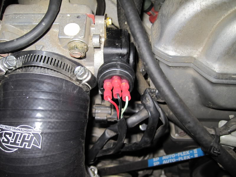
I checked the plugs on the BMW TPS and the way it is setup in my picture is wrong! I now have it as Black, Red, green. Works fine, but the voltage range is less than two volts.
And the boost controller clicks like it should but doesn't work.
I checked the plugs on the BMW TPS and the way it is setup in my picture is wrong! I now have it as Black, Red, green. Works fine, but the voltage range is less than two volts.
And the boost controller clicks like it should but doesn't work.
Reply
0
0
07-10-2009, 05:04 PM
#10
Senior Member
Thread Starter
iTrader: (3)
Join Date: Apr 2006
Location: Northern Michigan
Posts: 900
Total Cats: 0
Does anyone here have a config file for 90-93 /460cc/ Variable TPS/ boost control, so I can look at and compare the Accel/Deccel information and Boost Control setup?
I need to put this to rest and stop bugging people.
I need to put this to rest and stop bugging people.
Reply
0
0

Thread
Thread Starter
Forum
Replies
Last Post
Zaphod
MEGAsquirt
47
10-26-2018 11:00 PM


