When you click on links to various merchants on this site and make a purchase, this can result in this site earning a commission. Affiliate programs and affiliations include, but are not limited to, the eBay Partner Network.
Modulus key.
Failure mode also important.
Does it stay bent or shatter.
Abrasion resistance.
Cost per square/ft.
Before Alumalite, birch was the next best thing to Tegris or dry carbon.
Modulus key.
Failure mode also important.
Does it stay bent or shatter.
Abrasion resistance.
Cost per square/ft.
Before Alumalite, birch was the next best thing to Tegris or dry carbon.
That is an interesting point you make.
Perhaps there needs to be an idea of where the bend shatter cross over is.
Although given the range being very grouped I guess it won't be accurate.
I've been considering whipping up a wing setup for my car, and an end plate mounted wing came to mind, since big end plates seem to help with efficiency and normal uprights disrupt flow.
Is there a good reason why they're not used in GT cars or other racing? It's prevalent in F1 , but I wasn't sure if that was due to a restriction on F1s side, or a restriction in other race classes. the NOPRO guys used it on their GT300 car, but that wasn't exactly a winning car.
Not used on GT3 cars due to rules- note they are used on LMP cars.
Mounting on a Miata is a challenge, note how small the wing in that picture is. To have a full sized 65-68" wing you need to make some kind of fender mounts.
It's often easier, lighter, cheaper and stronger to just have a gooseneck setup. Which you often see on GT/GTLM cars.
Question to those who run a splitter + flat underbody (+ diffuser): do you still run the stock undertray? I've seen a lot of splitter setups, yet nobody seems to shield the engine bay from the high pressure wheel well area. I guess this must decrease radiator efficiency, wouldn't it? Or does the wheel well have less pressure than the bay?
I have full splitter only and ditched my undertray. Front airdam is tightly ducted to radiator and I have both hood vents and fender vents. I figure the combination of those two should be adequate to pull some air out of the bay, not that I'm really concerned about bay temps- my intake tube is wrapped and ducted though the headlight, and nothing else under there is going to get hot enough to care.
I retain the stock undertray, but the fender liners are both missing.
The wheelwell holes by the headlights are problems. Fender liners or front mini tubs would be huge to minimize wheelwell air volume. Build them as close to full bump travel as possible.
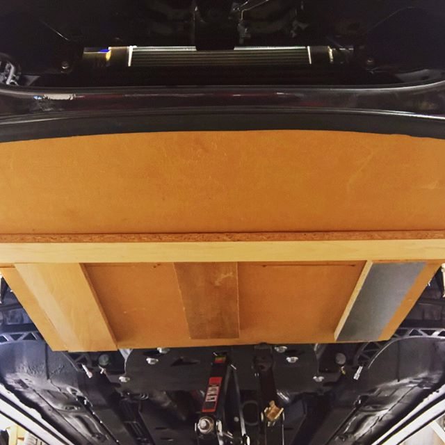
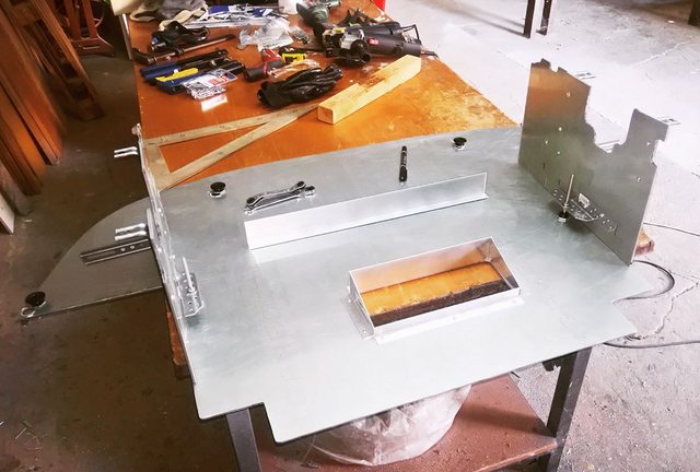
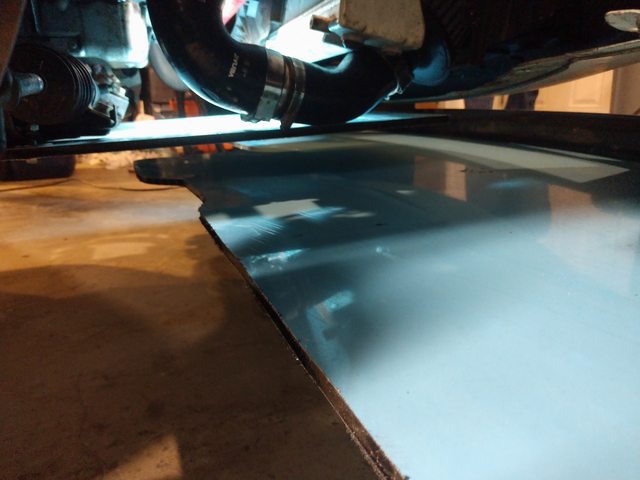
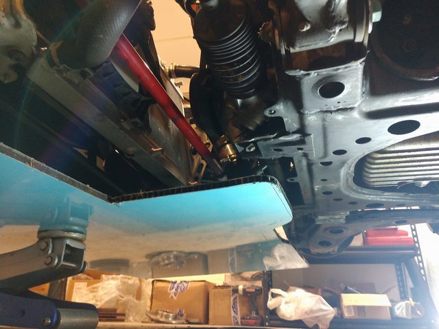
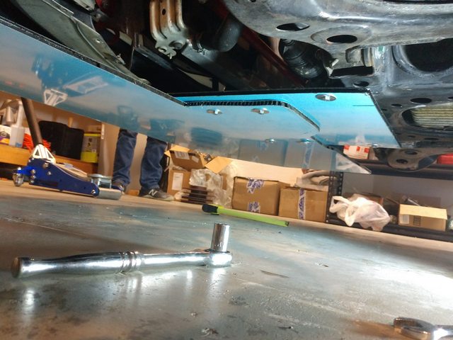
Not sure what we are looking at. You appear to have an alumalite undertray and then he wooden one underneath that.
If the wood under tray is the final product those reinforcing braces are going to get caught on stuff if you drop a wheel off track. It needs to be smooth underneath for it to work, and survive. Also that oil color does not appear to have any ducting. Is that the final iteration or are you going to enclose it somehow?
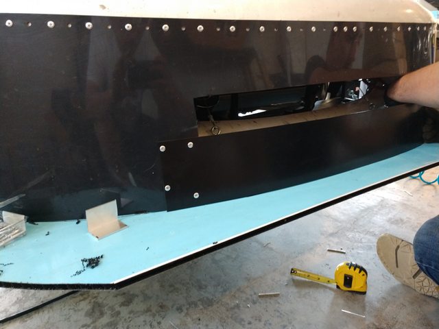
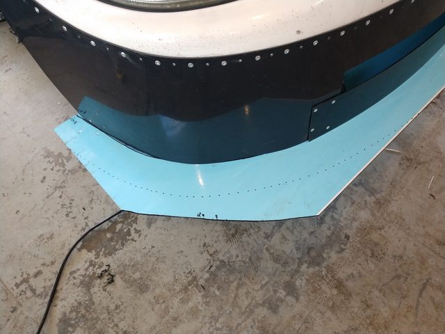
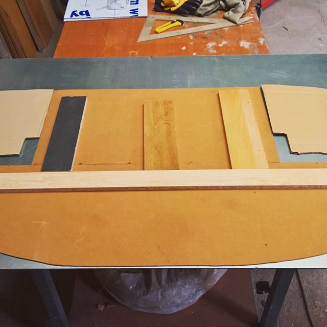
I just wanted to show the process to design my template.
Final product is a composite (not alumalite itself).
Flat floor has two security bolts to the lower subframe and rest of them are quick fasterners.
I will design front splitters and canards tomorrow (only for track events because they can�t be MOT registered and i use my car almost for daily).
Something easy to mount and not so big.
no pics yet as i'm still thinking about my aero and ducting.. and i have a question.
it seems like the "right" opening size for the colling intake is about 1/3 of the radiator
What about if your add IC, and oil cooler ? Is it about "1/3 of the total surfaces, adding the surface of each radiators" or "1/3 of the visible surface"? IC will be probably in fornt of the rad, and oil cooler and i'm trying to find some "free flow", all this for a track car...
Yes that is right 1/3 of the size of the heat exchangers. Now keep in mind following other race cars will lessen the air flow.
i'll try not to stay behind for too long in order to keep my temps low enough
Just to make sure i got it right , if i have a an 65cmx30cm radiator and a 55x18cm (sorry for the metrics) my intake should be around (1 000cm� which could translate in an opening for the air intake of appr. 55x18cm).
Also, I intend to divide the intake in 2 parts :
- bottom half going through the IC and then to the bottom part of rad,
- top half going through the top half of the radiator.
do i overthink it?
i try to do it once do it right, measure twice cut once....so I ask many times!
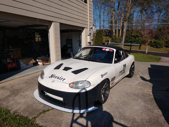
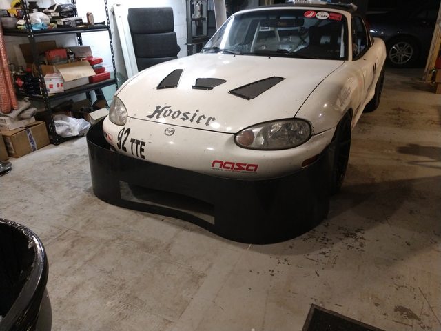
Dollars spent: $250ish Hours spent: 16+ How effective: 2 0=slower, 1, no improvement, 2 =slightly better,3= big improvement Materials used: 0.100" HDPE, 10mm alumalite, turn-buckles/wires, 6x nuts/bolt/fender washers and rivets.......lots of rivets Bracket location: Hard-mount in OEM holes for rear of under-tray. Cable-wire/turn-buckles for front and side mounting points. L-brackets on splitter for air-dam to rest on. Tracks tested on: Roebling Road Race/TT class built for: ST5/TT5/GLTC
Admittedly, a buddy and me slapped this together in a hurry. Did my best to off-set the rear downforce of the 9LR 64" swan-neck, even at 0 AOA.
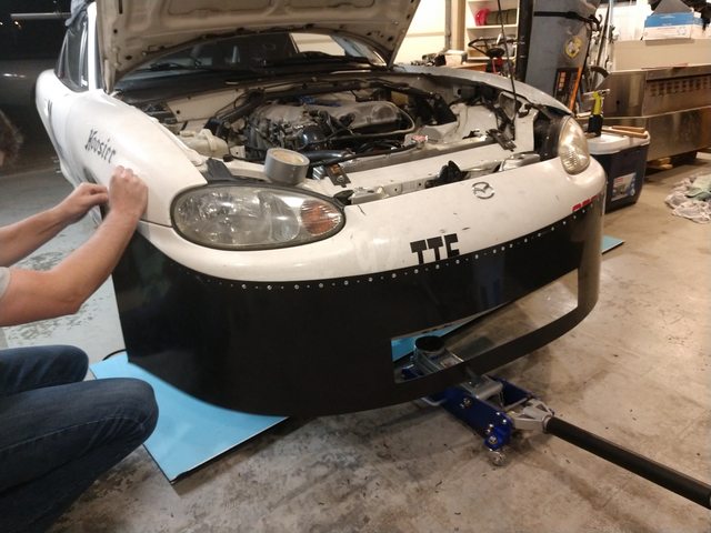
This was put together with 9LR prototype air-dam made out of 0.100" HDPE. It has about 3x as many rivet holes as needed, I needed up using every other hole, which is still 40 rivets across the top of it. Thank god for air rivet gun!
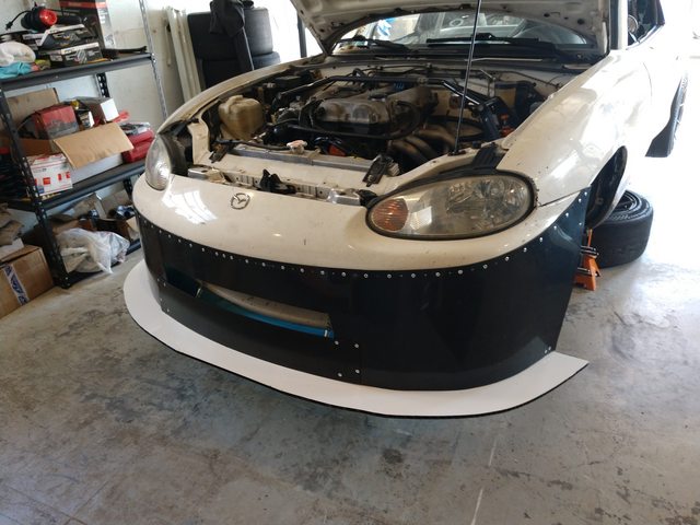
Mocking the air-dam up, I attempted to mount it on the furthest edge possible on the front bumper. Lining up this pre-cut prototype up with the very top of the bumper edge where it meets the fenders. I figured I didn't want it to be riveted to the fender in case of contact and for ease of disassembly on the fenders.
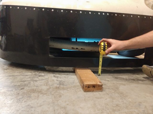
Once mounted, we realized it was low as damnit. So we'll have to do some custom fab work with box-cutter later. 2x4 for reference.......
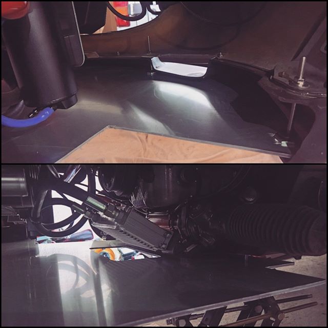
Got the left-over alumalite mocked up as well..... quickly noticed if this piece is mounted level with the subframe it'll point straight at the opening of the mouth of the air-dam. OR have so much AOA that'll dig into anything it gets near like..... sand, dirt, grass, curbs, or even loading ramps
Also noted the left-over piece doesn't quite reach the sub-frame if I intended to do a ~3" splitter lip.
So we opted for a uuhhh..... "modular" design here. Cut the very edge of this alumalite, drilled holes for sub-frame, mocked it onto main piece, drilled a few more holes, and fastened it together.
Thankfully during mock-up and I had the fore-sight to make sure the holes were 1. accessible from the top to tighten 2. don't send the drill-bit into something important, like the steering rack or oil-pan
Used some cable-wire, turn-buckles with J-hooks on one side, and eye-lit bolts with bigass washers. Mounted two in the front to the edge of the mouth, using the two bolts on the bumper support. Two others mounted on the sides using two bolts right off the frame.
(Note: I stole this idea from Dan ) This actually works out pretty damn well and I'd recommend it. I would like to find a way to get the bottom of the eye-lit bolts counter-sunk or flush with the under-tray though. Maybe version 2 will have that?
As you can see here, after cutting the bottom of the air-dam to line up with the "modular" splitter there's not much material of the air-dam at the bottom of the mouth opening. It's also super low, so not ideal for air-flow since I did not do/have time for proper ducting.
We cut the mouth higher and added a spare piece of ABS to cover the bottom and of course.... more rivets! Also pictured, is one of the L-brackets. I got some 1.5" aluminum angle stock and cut it into multiple 2", 1", and 1/2" slivers. Drilled holes into one side and riveted them onto the splitter following a tight path around the airdam. Carefully not surpassing 5* of air-dam angle
Marked the 3" lip with super precision and took the air-saw to it.
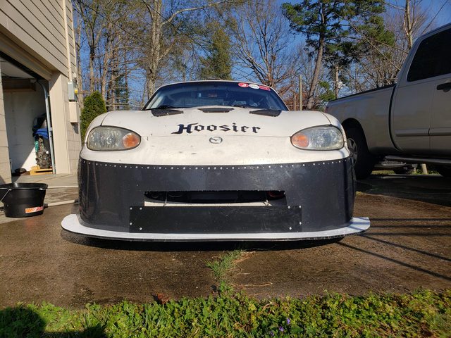
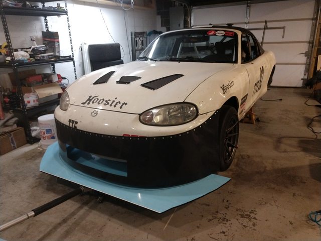
Relatively finished here. Ended up doing some more cutting on the air-dam to prevent the bulging on the sides in front of the wheels.
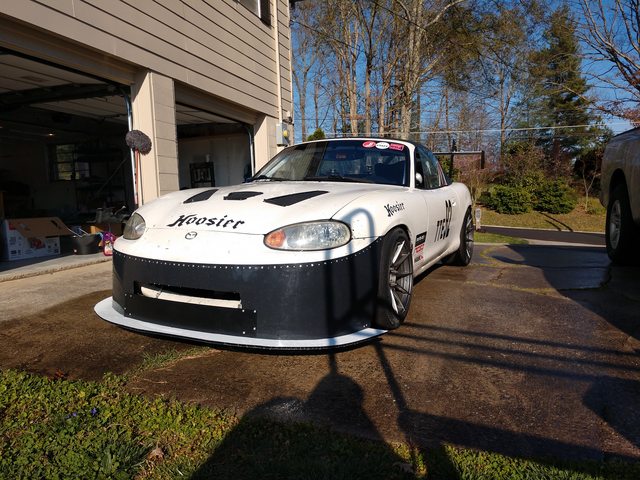
And on the ground!
Additional notes:
The mouth turned out to be too small for drafting. Car crept up to 3/4 on OEM temp gauge while drafting for 1/4 of a lap(2.2mile course) while it was slight over-cast and ~75* ambient. My miata has 37mm Koyo v-core and Qmazxreroute. Ducting would resolve this problem while in a draft with this size of an opening, IMO.
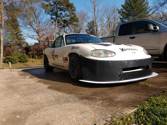
The car gained 5hp, lost ~150lbs, and added this aero package since the last time I was at Roebling.
Previous times in TTE trim of 130rwhp, 2440lbs,Xida800/500,RB1.125"/14mm, 205 R7s, 15x9s - 1:21.7xx - 1:23.0xx
New times in TT5 trim of 135rwhp, 2300lbs, Xida800/500,RB1.125"/14mm, 205 R7s, 15x8s - 1:19.4xx - 1:21.7xx
The largest difference with this aero both my co-driver and I noticed was how settled it was on a slip-angle. It required smaller inputs to correct to squiggle thru. Unfortunately I was not running AiM data two years when I was at Roebling last :(
So much for trying to post text with photos.
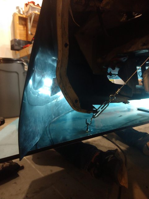
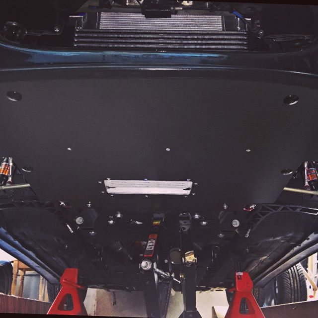
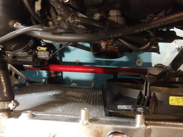
Went kind of old school using the theory just do what Andrew does.
Have a gorgeous piece of directional carbon nomex honeycomb sitting in the garage but 1/2" birch is so easy and cheap. Not "that" heavy.
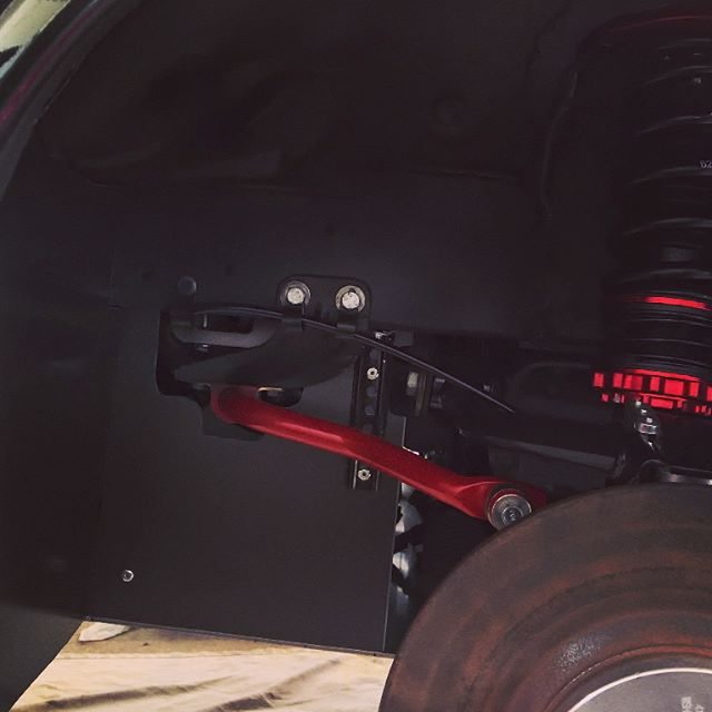
Used rivnuts and aluminum mounts tapping holes in frame for countersunk fasteners.
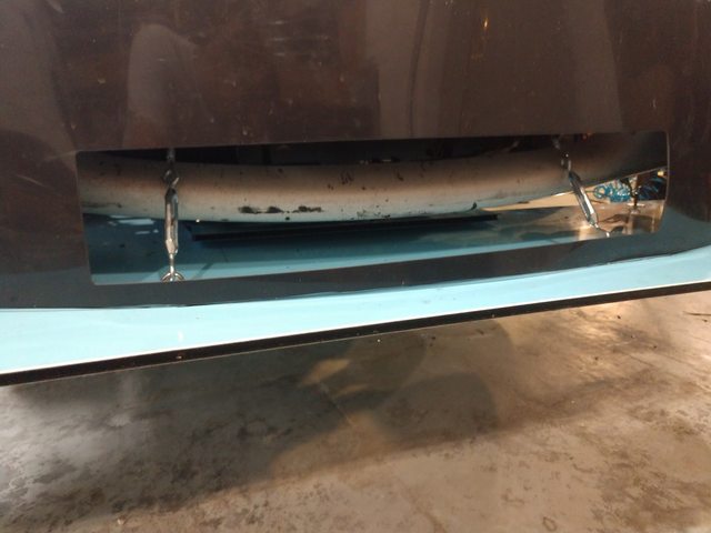
Oil cooler was in the way of the latest trend in mounting bracket so had to go a bit back and use sailboat rigging at the front.


 10-22-2018, 06:11 PM


 0
0


 ) This actually works out pretty damn well and I'd recommend it. I would like to find a way to get the bottom of the eye-lit bolts counter-sunk or flush with the under-tray though. Maybe version 2 will have that?