Hornetball's Build
 09-02-2011, 01:00 AM
#81

Unfortunately my wife is the same way, counting down the days.
I tried getting gas there two days in a row but the line for each pump was at least three cars not worth my time to wait.
I tried getting gas there two days in a row but the line for each pump was at least three cars not worth my time to wait.
Yes. They have a smoking deal on gas right now. Filled the wife's 4x4 Expedition and my Poncho G8 GT there the previous day. A little bit embarassing putting fuel into the tiny Miata gas tank after filling those brawny V8 tanks. It's also the closest station to my house!! My wife is super-excited about the new HEB opening. We live a dull life.

Reply
 0
0

0
09-09-2011, 03:11 PM
#82
Elite Member
Thread Starter
iTrader: (4)

Join Date: Mar 2008
Location: Granbury, TX
Posts: 6,301
Total Cats: 696
Cross-posted from Megasquirt forum.
Step 1: Wastegate Only:
I've taken a building block approach to EBC with my MSPNP. For the first couple of months after turbo install, I just concentrated on tuning my basic performance on the wastegate. This was facilitated by an "EBC Enable/Disable" toggle switch that I hid in my engine compartment (since my youngest daughter starts driving in October and has her eyes set squarely on the Miata). This is what my basic Greddy wastegate control looks like on a 3rd gear pull:
Overall, the control isn't bad. The wastegate kicks in at around 3300RPM and 5.2psi of boost. From 3300RPM to 6900RPM, there is a gradual 2.5psi of boost creep. Two things contribute to boost creep on my car:
1. I don't run an intercooler, therefore there is no pressure loss as the intake flow increases with RPM.
2. I run a performance cat and a 2.5" exhaust which gives less back pressure than stock. I use the stock Greddy downpipe with some porting. This tends to skew more of the exhaust flow through the turbine instead of the wastegate as flow increases.
Before delving into any form of boost control, you need to ensure that your wastegate basically works so that your boost control has a chance of controlling things. Also, your target boost needs to be higher than the maximum boost generated by the wastegate. The curve here is easily controllable and my boost target of 10psi is comfortably above 7.7psi. So, on to the next step.
Step 2: Open Loop EBC:
My next step was open loop EBC. I followed the directions in the MSPNP manual for this. Basically, you:
1. Setup the valve parameters;
2. Disable closed loop control; and
3. Tune valve duty cycle targets.
For valve parameters, I bought the DIY EBC valve and just used the defaults. Didn't mess with it. Seems to work.
There are a couple of ways to disable the closed loop control. The MSPNP manual recommends setting all cells of your "Boost kPa Target" table to 70kPa and the "Closed Loop kPa Limit" to 20kPa. Thus, so long as your MAP is at 90kPa or above (as it will be in boost), you will be beyond the "Closed Loop kPa Limits" and operating on open-loop duty cycles.
The other way to disable closed loop control is simply to set 0 as the "Closed Loop kPa Limit." Due to the normal noise on the MAP signal, this condition will never be true except for rare, momentary transitions.
Tuning the valve duty cycles is straightforward. What I did was log a series of third gear pulls with my entire duty cycle table set to a contant value. I would do the third gear pull until I either hit my RPM limit or my boost limit. This was my sequence:
1. Set duty cycle table to 100%. This essentially keeps the EBC valve and wastegate closed.
2. Perform a third gear pull. On this first run, you need to be careful because you are going to hit your boost limit WAY before your RPM limit. This run establishes the lowest RPM at which you can hit your target boost.
3. Set duty cycle to 90%.
4. Perform a third gear pull.
5. Repeat the above while incrementally lowering the duty cycle until you are hitting your RPM limit without hitting your boost limit.
With logs in hand, analyze to determine your DC vs. RPM curve for your target boost. My values were:
100%DC -- 3900RPM
90%DC -- 3950RPM
80%DC -- 4000RPM
70%DC -- 4100RPM
60%DC -- 4350RPM
55%DC -- 4400RPM + Held 10psi to Redline
50%DC -- Hit 9psi at 3900RPM and held 9psi to Redline
Armed with the above information, and with the benefit of a few 3rd gear pulls to smooth overshoots and undershoots, I ended up with the following duty cycle target table:
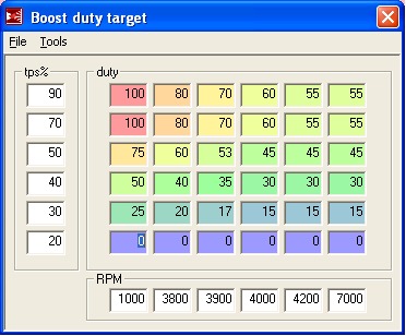
Note that since I have a TPS, I reduced the duty cycles at lower throttle positions to produce more linear throttle response and relieve turbine load at part throttle. This part is strictly optional.
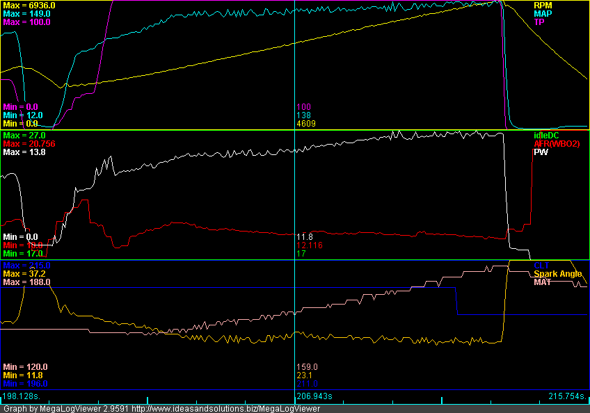
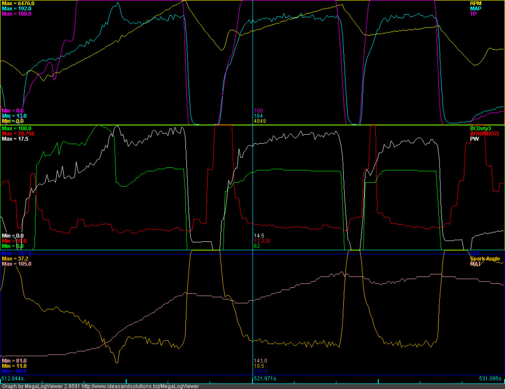
Here's what an open-loop third gear pull looks like:
Control is good. You can see the rapid boost ramp from keeping high duty cycles at low RPMs. There is a slight overshoot where EBC starts really controlling around 3900RPM. These is also a slight sag in the middle and a little boost creep at the end. This pull shows boost controlled between 8.5-10psi (average around 9psi). With some more tuning, I'm sure I could get that line straighter.
This pull also illustrates the deficiency in open-loop EBC. The day I tuned it, my average was 10psi. On the day that I logged this pull, it generated 9psi. Open-loop EBC cannot target a boost level. It just sets up physical operating parameters for the valve based upon RPM and TPS. The boost you get depends entirely upon external conditions (atmospheric pressure and temperature, engine compartment heat soak, etc.). This is kind of annoying.
Step 3: Closed-Loop EBC:
So, I lived with Open-Loop EBC for awhile. It was pretty good, and I just tolerated that it would control to "around" 10psi. The word around MT.net was that Closed-Loop EBC didn't work on the MS1. If you wanted closed-loop, you needed at least an MS2. The MSPNP directions were equally discouraging, descibing closed-loop as "experimental" and "use at your own risk."
Well, my friends, the above is total bullshit. Closed-loop EBC works just fine on the MS1. Read on.
One evening, I was driving home from work, and open-loop was only hitting around 8psi. There had been some recent, dramatic weather changes in our area (we were FINALLY below 100�F -- actually, well below), and this was impacting where open-loop was settling. I was near my 3rd gear pull test area, and I had my laptop with me . . . what the heck, let's give it a try.
I setup my target boost table, and left the default values for Proportional Gain (49.8%), Differential Gain (9.8%) and Closed Loop kPa Limit (20kPa). Did a 3rd gear pull. It wasn't pretty (�3psi), but it was obviously controlling. Time to tune.
The MS1 code provides for both proportional and differential gain. Tuning proportional control loops is simple, and you can always achieve a safe and stable gain. Differential is a lot trickier, and depends upon a very clean relationship between the control variable and the control parameter to be useful. Our MAP signal is just plain too noisy for it to be of any use, so I ignored it. After setting Differential Gain to 0%, I did 4 3rd gear pulls and quickly settled on a Proportional Gain of 15% and a Closed Loop kPa Limit of 15kPa. I also made sure that my kPa target table had easily attainable targets around the 4000RPM corner to minimize control overshoots. This is where I ended up with my closed loop parameters:
And here's a 3rd gear pull:
Works well! Still a slight overshoot at the corner, but beyond we're at 10psi �0.5psi. And, theoretically, this control method should not be dependent upon weather conditions (although I've only been running it this week -- we'll see how it handles more drastic weather changes).
Comparisons:
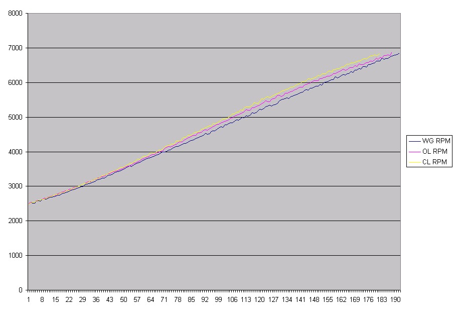
Here's a comparison of the three control methods in RPM vs. Time. Note that time is in MS logging frequency units (~16Hz -- a value of 160 is about 10 seconds). The lines are 2500RPM to 6900RPM pulls. The steeper the line, the faster the acceleration. More boost = more power . . . no suprise here.
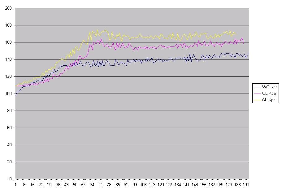
Here's another comparison of kPa vs. Time for the same three pulls. Pretty happy with the closed-loop line.
Conclusions:
1. Closed-loop EBC on MS1 works just fine. Use it.
2. Make sure you do things in sequence. Step 1 is to make sure your wastegate can adequately control boost.
3. Step 2 is to tune open loop. This is important. Not only is open-loop the fallback control method if closed-loop doesn't work, but it also provides the basic duty cycle value that the closed-loop algorithm modifies to achieve desired boost. If it is way off, you don't have a chance.
4. Step 3 is to tune closed loop. Apply KISS. Do proportional only and take it easy with the gains and targets so you get good control.
Step 1: Wastegate Only:
I've taken a building block approach to EBC with my MSPNP. For the first couple of months after turbo install, I just concentrated on tuning my basic performance on the wastegate. This was facilitated by an "EBC Enable/Disable" toggle switch that I hid in my engine compartment (since my youngest daughter starts driving in October and has her eyes set squarely on the Miata). This is what my basic Greddy wastegate control looks like on a 3rd gear pull:
Overall, the control isn't bad. The wastegate kicks in at around 3300RPM and 5.2psi of boost. From 3300RPM to 6900RPM, there is a gradual 2.5psi of boost creep. Two things contribute to boost creep on my car:
1. I don't run an intercooler, therefore there is no pressure loss as the intake flow increases with RPM.
2. I run a performance cat and a 2.5" exhaust which gives less back pressure than stock. I use the stock Greddy downpipe with some porting. This tends to skew more of the exhaust flow through the turbine instead of the wastegate as flow increases.
Before delving into any form of boost control, you need to ensure that your wastegate basically works so that your boost control has a chance of controlling things. Also, your target boost needs to be higher than the maximum boost generated by the wastegate. The curve here is easily controllable and my boost target of 10psi is comfortably above 7.7psi. So, on to the next step.
Step 2: Open Loop EBC:
My next step was open loop EBC. I followed the directions in the MSPNP manual for this. Basically, you:
1. Setup the valve parameters;
2. Disable closed loop control; and
3. Tune valve duty cycle targets.
For valve parameters, I bought the DIY EBC valve and just used the defaults. Didn't mess with it. Seems to work.
There are a couple of ways to disable the closed loop control. The MSPNP manual recommends setting all cells of your "Boost kPa Target" table to 70kPa and the "Closed Loop kPa Limit" to 20kPa. Thus, so long as your MAP is at 90kPa or above (as it will be in boost), you will be beyond the "Closed Loop kPa Limits" and operating on open-loop duty cycles.
The other way to disable closed loop control is simply to set 0 as the "Closed Loop kPa Limit." Due to the normal noise on the MAP signal, this condition will never be true except for rare, momentary transitions.
Tuning the valve duty cycles is straightforward. What I did was log a series of third gear pulls with my entire duty cycle table set to a contant value. I would do the third gear pull until I either hit my RPM limit or my boost limit. This was my sequence:
1. Set duty cycle table to 100%. This essentially keeps the EBC valve and wastegate closed.
2. Perform a third gear pull. On this first run, you need to be careful because you are going to hit your boost limit WAY before your RPM limit. This run establishes the lowest RPM at which you can hit your target boost.
3. Set duty cycle to 90%.
4. Perform a third gear pull.
5. Repeat the above while incrementally lowering the duty cycle until you are hitting your RPM limit without hitting your boost limit.
With logs in hand, analyze to determine your DC vs. RPM curve for your target boost. My values were:
100%DC -- 3900RPM
90%DC -- 3950RPM
80%DC -- 4000RPM
70%DC -- 4100RPM
60%DC -- 4350RPM
55%DC -- 4400RPM + Held 10psi to Redline
50%DC -- Hit 9psi at 3900RPM and held 9psi to Redline
Armed with the above information, and with the benefit of a few 3rd gear pulls to smooth overshoots and undershoots, I ended up with the following duty cycle target table:
Note that since I have a TPS, I reduced the duty cycles at lower throttle positions to produce more linear throttle response and relieve turbine load at part throttle. This part is strictly optional.
Here's what an open-loop third gear pull looks like:
Control is good. You can see the rapid boost ramp from keeping high duty cycles at low RPMs. There is a slight overshoot where EBC starts really controlling around 3900RPM. These is also a slight sag in the middle and a little boost creep at the end. This pull shows boost controlled between 8.5-10psi (average around 9psi). With some more tuning, I'm sure I could get that line straighter.
This pull also illustrates the deficiency in open-loop EBC. The day I tuned it, my average was 10psi. On the day that I logged this pull, it generated 9psi. Open-loop EBC cannot target a boost level. It just sets up physical operating parameters for the valve based upon RPM and TPS. The boost you get depends entirely upon external conditions (atmospheric pressure and temperature, engine compartment heat soak, etc.). This is kind of annoying.
Step 3: Closed-Loop EBC:
So, I lived with Open-Loop EBC for awhile. It was pretty good, and I just tolerated that it would control to "around" 10psi. The word around MT.net was that Closed-Loop EBC didn't work on the MS1. If you wanted closed-loop, you needed at least an MS2. The MSPNP directions were equally discouraging, descibing closed-loop as "experimental" and "use at your own risk."
Well, my friends, the above is total bullshit. Closed-loop EBC works just fine on the MS1. Read on.
One evening, I was driving home from work, and open-loop was only hitting around 8psi. There had been some recent, dramatic weather changes in our area (we were FINALLY below 100�F -- actually, well below), and this was impacting where open-loop was settling. I was near my 3rd gear pull test area, and I had my laptop with me . . . what the heck, let's give it a try.
I setup my target boost table, and left the default values for Proportional Gain (49.8%), Differential Gain (9.8%) and Closed Loop kPa Limit (20kPa). Did a 3rd gear pull. It wasn't pretty (�3psi), but it was obviously controlling. Time to tune.
The MS1 code provides for both proportional and differential gain. Tuning proportional control loops is simple, and you can always achieve a safe and stable gain. Differential is a lot trickier, and depends upon a very clean relationship between the control variable and the control parameter to be useful. Our MAP signal is just plain too noisy for it to be of any use, so I ignored it. After setting Differential Gain to 0%, I did 4 3rd gear pulls and quickly settled on a Proportional Gain of 15% and a Closed Loop kPa Limit of 15kPa. I also made sure that my kPa target table had easily attainable targets around the 4000RPM corner to minimize control overshoots. This is where I ended up with my closed loop parameters:
And here's a 3rd gear pull:
Works well! Still a slight overshoot at the corner, but beyond we're at 10psi �0.5psi. And, theoretically, this control method should not be dependent upon weather conditions (although I've only been running it this week -- we'll see how it handles more drastic weather changes).
Comparisons:
Here's a comparison of the three control methods in RPM vs. Time. Note that time is in MS logging frequency units (~16Hz -- a value of 160 is about 10 seconds). The lines are 2500RPM to 6900RPM pulls. The steeper the line, the faster the acceleration. More boost = more power . . . no suprise here.
Here's another comparison of kPa vs. Time for the same three pulls. Pretty happy with the closed-loop line.
Conclusions:
1. Closed-loop EBC on MS1 works just fine. Use it.
2. Make sure you do things in sequence. Step 1 is to make sure your wastegate can adequately control boost.
3. Step 2 is to tune open loop. This is important. Not only is open-loop the fallback control method if closed-loop doesn't work, but it also provides the basic duty cycle value that the closed-loop algorithm modifies to achieve desired boost. If it is way off, you don't have a chance.
4. Step 3 is to tune closed loop. Apply KISS. Do proportional only and take it easy with the gains and targets so you get good control.
Reply
0
0
12-11-2011, 07:01 PM
#83
Junior Member


Join Date: Nov 2011
Location: Helsinki, Finland
Posts: 45
Total Cats: 7
well there was me gonna start a thread regarding fitting similar stuff to my 91 greddy MX, but that seems kinda pointles now as i found some sort of bible!
Big thanks to you Hornetball!
TB
Big thanks to you Hornetball!
TB
Reply
0
0
01-09-2012, 03:16 PM
#84
Elite Member
Thread Starter
iTrader: (4)
Join Date: Mar 2008
Location: Granbury, TX
Posts: 6,301
Total Cats: 696
Cross-posted from the Megasquirt forum.
So, I finally figured out (with the help of some code inspection) Closed-Loop EBC on my MSPNP9093. I've been meaning to post the details, but got sidetracked by life. The delay has confirmed that, when tuned properly, the MS-1 CLEBC works consistently and is not affected by temperature. I've been operating it since early September without any changes. So far in North Texas, I've seen well North of 100 and well South of 30. The algorithm just works, it goes to and holds my target day in and day out. So, without further ado ...:
Prerequisites:
Before tackling CLEBC, it is assumed that you've setup and tuned Open Loop EBC. See two posts above for details on this. A well setup OLEBC is critical to getting your CLEBC working correctly. In addition, some of the data that was used to setup OLEBC will be re-used for CLEBC.
The other thing that is needed to successfully use CLEBC is a throttle position sensor. Make sure to get one installed and working before attempting this.
The Revelation:
I "sort of" got CLEBC working just by playing around with the "Proportional Gain" and "Differential Gain" values. However, when starting from low RPM's, I typically got boost overshoots -- which didn't make any sense for a true Proportional control algorithm. This was a typical pattern:
Notice the boost overshoot in second gear. You can also see that the boost control solenoid duty cycle goes to near 100% and then suddenly drops down when this happens (logged as "BCDuty3").
So, I dug into the code and found that the MS-1 uses an Integral+Derivative control loop for CLEBC. There is no proportional term at all. The algorithm is:
Duty Cycle(new) = Duty Cycle(old) + "Proportional Gain" x ( kPa Target - kPa ) - "Differential Gain" x ( kPa(current) - kPa(previous) )
if Duty Cycle(new) > 100% then Duty Cycle(new) = 100%
if Duty Cycle(new) < 0% then Duty Cycle(new) = 0%
What this means is that the algorithm is prone to integral windup, and it is up to us to ensure that integral windup doesn't happen.
Integral Windup:
I know what you're thinking. "OK, Mr. Smarty Pants, what the heck is 'integral windup'?"
Well, I'm older than most of you. In fact, I'm nearly as old as Curly! Contributing to my advanced age are two daughters, one who is grown and married and almost completely returned by the aliens, and another who has recently been taken by those same aliens (she's 15). In my mind, the best way to explain integral windup is with an analogy to a teenage daughter. Here's an example of the daily fight between my wife and my teenage daughter:
Wife: "Clean your room" or "Do your homework" or "Get off the computer" or (fill in the blank).
Daughter: (Assuming she responds at all) "Yeah, whatever . . ."
Wife (more loudly): "Clean your room" or "Do your homework" or "Get off the computer" or (fill in the blank).
Daughter: (Same response)
Wife (even more loudly): "Clean your room" or "Do your homework" or "Get off the computer" or (fill in the blank).
Daughter: (Same response)
. . . and so on.
In the end, my poor wife has made continuous control inputs into a system (a teenage daughter) that is fundamentally not controllable. The desired system response is not achieved. However, my wife gets totally wound up and pissed off -- which then affects my life negatively. This, my friends, is integral windup.
What does the above have to do with CLEBC? Plenty. There are regions where boost does not (cannot) respond to EBC valve duty cycle changes. If we are in one of these regions and attempt to perform CLEBC with an integral+derivative algorithm, the only thing that will happen is that the EBC valve duty cycle will get wound up and pissed off -- it will rise to 100% or fall to 0% (thankfully, it is limited to these values). Despite this, the target boost will not be achieved. And, once we get into a region where the system is responsive, the CLEBC algorithm will have a lousy starting point and a much more difficult problem to solve -- leading to boost overshoots and undershoots.
There are two regions where this happens:
1. When the throttle isn't open. Megasquirt uses MAP as an indication of boost. MAP, by definition, is sourced AFTER the throttle. As we all know, the throttle is the primary and most powerful control for MAP. If you are trying to control boost (i.e., MAP) with EBC valve duty cycle and the throttle is closed or partially closed, you are wasting your time.
2. Before the turbo spools up. If the engine isn't in an RPM region where the turbo can generate boost, you can be at 100% EBC valve duty cycle all day long and boost won't rise at all.
So, How Can We Use CLEBC and Avoid Integral Windup?
Elementary. Use a hybrid of OLEBC and CLEBC. CLEBC is used in the regions where boost (i.e., MAP) is responsive to EBC valve duty cycle. OLEBC is used everywhere else. This is why it is critical that OLEBC be tuned first.
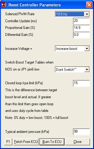
Looking at the EBC controls, there is a parameter called "Closed Loop kPa Limit (kPa)."
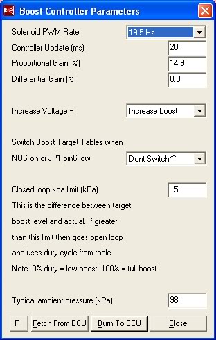
This parameter is intended to be a safety that forces use of OLEBC when it is apparent that CLEBC is not working. It does this by comparing currently sensed boost to the target boost in the "Boost kPa Target" table. A side effect of this parameter is that, if we are clever with our "Boost kPa Target" table, we can actually control the regions where OLEBC and CLEBC are used.
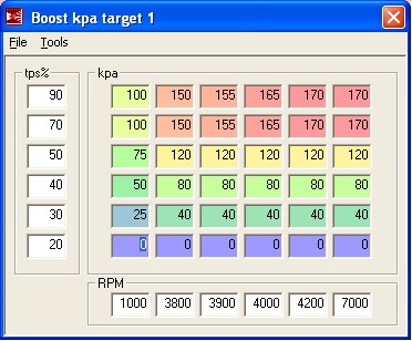
Here's an example (this is what I'm currently using, BTW):
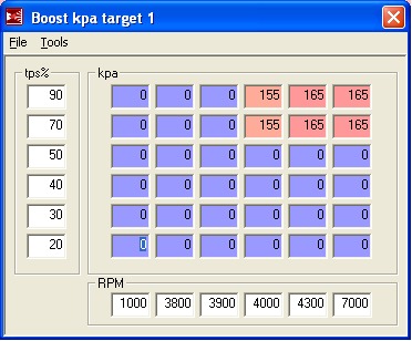
As you can see, I've entered a target of "0" in the areas where I want to use OLEBC, namely at small throttle settings and at low RPMs. Since "0" will naturally fall outside of the "Closed Loop kPa Limit (kPa)", I am forcing OLEBC in those areas. The idea is for OLEBC to handle these transient/uncontrollable regions and to give CLEBC a decent starting point at the handoff.
A few implementation details:
1. Determine the minimum RPM for using CLEBC by using the data collected during OLEBC tuning. Basically, with OLEBC set to 100%DC, the lowest RPM where target boost is achieved will be the minimum RPM for CLEBC.
2. Minimum TPS% is set based upon a knowledge of the flow characteristics of butterfly valves (the throttle is such a valve). Basically, by the time you're at 70% throttle, the effect of EBC valve duty cycle will be evident on MAP (assuming you are in the RPM range for boost).
3. The handoff point from OLEBC will vary depending upon external conditions. Because of this, you want to set the "Closed Loop kPa Limit (kPa)" to a value that accounts for OLEBC variability. Currently, I'm using 30kPa for this value and it has been working for the temperature extremes I've seen.
4. When setting the "Proportional Gain" and "Differential Gain" values, it helps to plot EBC valve duty cycle. In my installation, this is the "BCDuty3" parameter. What you are shooting for is a curve that expeditiously achieves your boost target without a lot of overshoot or oscillations. I'm currently using a "Proportional Gain" of 20 and a "Differential Gain" of 0.
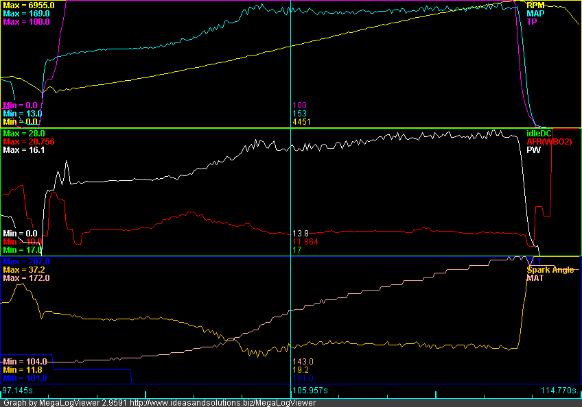
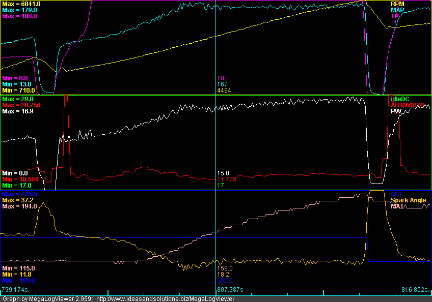
Here are some sample plots:
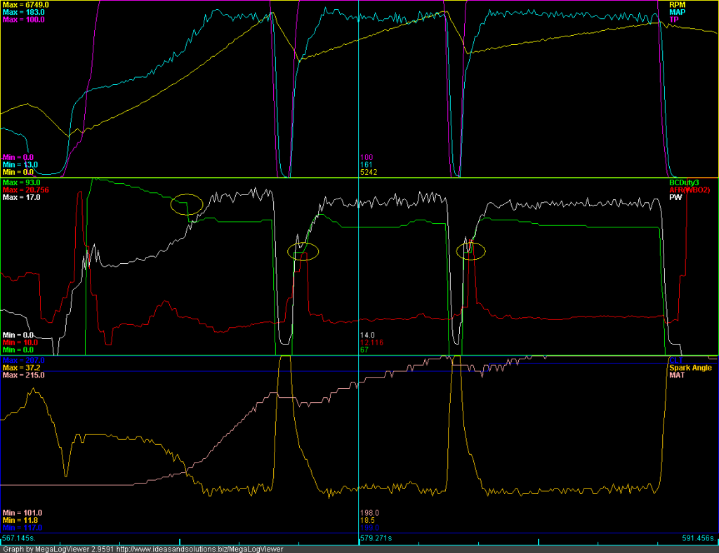
This plot was made on September 13 in some pretty hot conditions (notice minimum MAT is 101 and maximum MAT is 215). I circled the OLEBC to CLEBC handoff points in yellow. You can see that after handoff, the CLEBC seeks its target dynamically. On this particular day, CLEBC was settling to 67%DC.
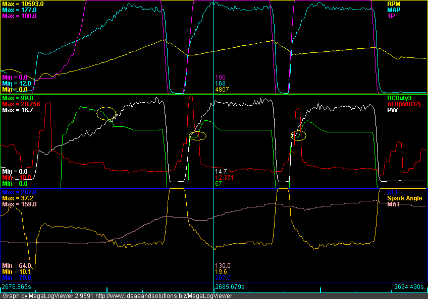
This plot was made yesterday evening in cool conditions (notice minimum MAT is 64 and maximum MAT is 159). Again, the ODEBC to CLEBC handoff points are circled in yellow. On this particular day, CLEBC was settling to 59%DC. This makes sense. In cooler conditions, it takes less DC to achieve a boost target.
YMMV.
So, I finally figured out (with the help of some code inspection) Closed-Loop EBC on my MSPNP9093. I've been meaning to post the details, but got sidetracked by life. The delay has confirmed that, when tuned properly, the MS-1 CLEBC works consistently and is not affected by temperature. I've been operating it since early September without any changes. So far in North Texas, I've seen well North of 100 and well South of 30. The algorithm just works, it goes to and holds my target day in and day out. So, without further ado ...:
Prerequisites:
Before tackling CLEBC, it is assumed that you've setup and tuned Open Loop EBC. See two posts above for details on this. A well setup OLEBC is critical to getting your CLEBC working correctly. In addition, some of the data that was used to setup OLEBC will be re-used for CLEBC.
The other thing that is needed to successfully use CLEBC is a throttle position sensor. Make sure to get one installed and working before attempting this.
The Revelation:
I "sort of" got CLEBC working just by playing around with the "Proportional Gain" and "Differential Gain" values. However, when starting from low RPM's, I typically got boost overshoots -- which didn't make any sense for a true Proportional control algorithm. This was a typical pattern:
Notice the boost overshoot in second gear. You can also see that the boost control solenoid duty cycle goes to near 100% and then suddenly drops down when this happens (logged as "BCDuty3").
So, I dug into the code and found that the MS-1 uses an Integral+Derivative control loop for CLEBC. There is no proportional term at all. The algorithm is:
Duty Cycle(new) = Duty Cycle(old) + "Proportional Gain" x ( kPa Target - kPa ) - "Differential Gain" x ( kPa(current) - kPa(previous) )
if Duty Cycle(new) > 100% then Duty Cycle(new) = 100%
if Duty Cycle(new) < 0% then Duty Cycle(new) = 0%
What this means is that the algorithm is prone to integral windup, and it is up to us to ensure that integral windup doesn't happen.
Integral Windup:
I know what you're thinking. "OK, Mr. Smarty Pants, what the heck is 'integral windup'?"
Well, I'm older than most of you. In fact, I'm nearly as old as Curly! Contributing to my advanced age are two daughters, one who is grown and married and almost completely returned by the aliens, and another who has recently been taken by those same aliens (she's 15). In my mind, the best way to explain integral windup is with an analogy to a teenage daughter. Here's an example of the daily fight between my wife and my teenage daughter:
Wife: "Clean your room" or "Do your homework" or "Get off the computer" or (fill in the blank).
Daughter: (Assuming she responds at all) "Yeah, whatever . . ."
Wife (more loudly): "Clean your room" or "Do your homework" or "Get off the computer" or (fill in the blank).
Daughter: (Same response)
Wife (even more loudly): "Clean your room" or "Do your homework" or "Get off the computer" or (fill in the blank).
Daughter: (Same response)
. . . and so on.
In the end, my poor wife has made continuous control inputs into a system (a teenage daughter) that is fundamentally not controllable. The desired system response is not achieved. However, my wife gets totally wound up and pissed off -- which then affects my life negatively. This, my friends, is integral windup.
What does the above have to do with CLEBC? Plenty. There are regions where boost does not (cannot) respond to EBC valve duty cycle changes. If we are in one of these regions and attempt to perform CLEBC with an integral+derivative algorithm, the only thing that will happen is that the EBC valve duty cycle will get wound up and pissed off -- it will rise to 100% or fall to 0% (thankfully, it is limited to these values). Despite this, the target boost will not be achieved. And, once we get into a region where the system is responsive, the CLEBC algorithm will have a lousy starting point and a much more difficult problem to solve -- leading to boost overshoots and undershoots.
There are two regions where this happens:
1. When the throttle isn't open. Megasquirt uses MAP as an indication of boost. MAP, by definition, is sourced AFTER the throttle. As we all know, the throttle is the primary and most powerful control for MAP. If you are trying to control boost (i.e., MAP) with EBC valve duty cycle and the throttle is closed or partially closed, you are wasting your time.
2. Before the turbo spools up. If the engine isn't in an RPM region where the turbo can generate boost, you can be at 100% EBC valve duty cycle all day long and boost won't rise at all.
So, How Can We Use CLEBC and Avoid Integral Windup?
Elementary. Use a hybrid of OLEBC and CLEBC. CLEBC is used in the regions where boost (i.e., MAP) is responsive to EBC valve duty cycle. OLEBC is used everywhere else. This is why it is critical that OLEBC be tuned first.
Looking at the EBC controls, there is a parameter called "Closed Loop kPa Limit (kPa)."
This parameter is intended to be a safety that forces use of OLEBC when it is apparent that CLEBC is not working. It does this by comparing currently sensed boost to the target boost in the "Boost kPa Target" table. A side effect of this parameter is that, if we are clever with our "Boost kPa Target" table, we can actually control the regions where OLEBC and CLEBC are used.
Here's an example (this is what I'm currently using, BTW):
As you can see, I've entered a target of "0" in the areas where I want to use OLEBC, namely at small throttle settings and at low RPMs. Since "0" will naturally fall outside of the "Closed Loop kPa Limit (kPa)", I am forcing OLEBC in those areas. The idea is for OLEBC to handle these transient/uncontrollable regions and to give CLEBC a decent starting point at the handoff.
A few implementation details:
1. Determine the minimum RPM for using CLEBC by using the data collected during OLEBC tuning. Basically, with OLEBC set to 100%DC, the lowest RPM where target boost is achieved will be the minimum RPM for CLEBC.
2. Minimum TPS% is set based upon a knowledge of the flow characteristics of butterfly valves (the throttle is such a valve). Basically, by the time you're at 70% throttle, the effect of EBC valve duty cycle will be evident on MAP (assuming you are in the RPM range for boost).
3. The handoff point from OLEBC will vary depending upon external conditions. Because of this, you want to set the "Closed Loop kPa Limit (kPa)" to a value that accounts for OLEBC variability. Currently, I'm using 30kPa for this value and it has been working for the temperature extremes I've seen.
4. When setting the "Proportional Gain" and "Differential Gain" values, it helps to plot EBC valve duty cycle. In my installation, this is the "BCDuty3" parameter. What you are shooting for is a curve that expeditiously achieves your boost target without a lot of overshoot or oscillations. I'm currently using a "Proportional Gain" of 20 and a "Differential Gain" of 0.
Here are some sample plots:
This plot was made on September 13 in some pretty hot conditions (notice minimum MAT is 101 and maximum MAT is 215). I circled the OLEBC to CLEBC handoff points in yellow. You can see that after handoff, the CLEBC seeks its target dynamically. On this particular day, CLEBC was settling to 67%DC.
This plot was made yesterday evening in cool conditions (notice minimum MAT is 64 and maximum MAT is 159). Again, the ODEBC to CLEBC handoff points are circled in yellow. On this particular day, CLEBC was settling to 59%DC. This makes sense. In cooler conditions, it takes less DC to achieve a boost target.
YMMV.
Reply
0
0
 01-17-2012, 06:35 PM
#86
Elite Member
Thread Starter
iTrader: (4)
Join Date: Mar 2008
Location: Granbury, TX
Posts: 6,301
Total Cats: 696
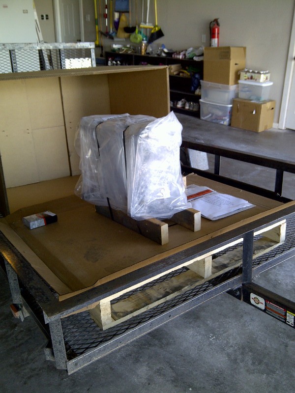
Look what I just got from the Fedex man!
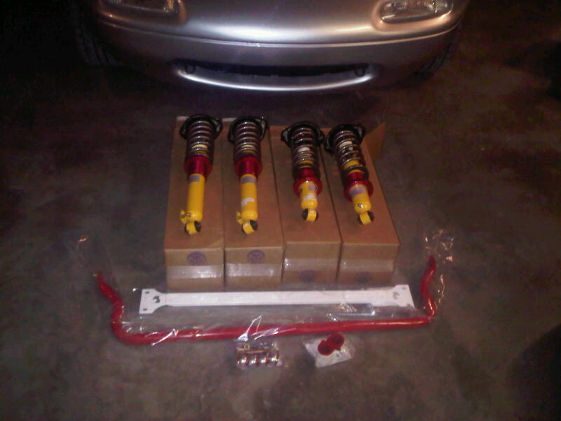
FCM Suspension (bought it on last year's group buy), RB tubular front sway with brace kit and adjustable end links.
After watching others dick around with multiple setups, I decided to just do it once and do it right.
Time to tear into the suspension. Plan to go through it with a fine tooth comb. Probably overdue considering I've got 192K on the stock suspension.
Reply
0
0
01-22-2012, 07:48 PM
#87
Elite Member
iTrader: (37)

Join Date: Apr 2010
Location: Very NorCal
Posts: 10,441
Total Cats: 1,899
I've got the same type of goodies from FCM on my car, replacing my 130k stock suspension. I've got a feeling you are going to love it! What rates did you go with and fixed, single, or double adjustable?
I popped in here to thank you for posting so much win and awesome in the Megasquirt threads, then I suddenly found myself ordering a PL-1598 and abusing my credit card with the Aircraft Spruce website. Thanks for posting detailed instructions, descriptions, and useful pictures for your projects, really helps to get me motivated!
Quick questions on the cowl intake: Have you driven the car in the rain yet? Ever worried about getting the filter wet?
Reply
0
0
01-22-2012, 10:00 PM
#88
Elite Member
Thread Starter
iTrader: (4)
Join Date: Mar 2008
Location: Granbury, TX
Posts: 6,301
Total Cats: 696
I ordered it back in September and went with Shaikh's recommendations. The spring rates were pretty high, but I can't remember what they were. I'll ask Shaikh when I call him for alignment specs. Unfortunately, I'm not going to able to mess with this for a bit due to schedule. Went with fixed (group buy suspension). Figure it's better to take variables out so you can focus on the real variable behind the steering wheel.
I have driven quite a bit in the rain (although we've been in a drought here). Our rainfall is similar to Cali. The filter is well protected and about an inch above the rain channel, although it does rest a bit on the shelf next to the rain channel. It's really hard to see the filter with the hood down and, given any forward velocity, not much chance of water going against the airflow. There's a fair bit of intake noise with this setup.
I have driven quite a bit in the rain (although we've been in a drought here). Our rainfall is similar to Cali. The filter is well protected and about an inch above the rain channel, although it does rest a bit on the shelf next to the rain channel. It's really hard to see the filter with the hood down and, given any forward velocity, not much chance of water going against the airflow. There's a fair bit of intake noise with this setup.
Reply
0
0
 04-12-2012, 03:03 PM
#90
Elite Member
Thread Starter
iTrader: (4)
Join Date: Mar 2008
Location: Granbury, TX
Posts: 6,301
Total Cats: 696
I humbly apologize. That must have been painful.
Yep. Injunere.
Hate to say it, but I haven't got the suspension on yet. Work is nuts, and the current project is a complete rebuild of the suspension on my wife's 380SL. That car is kicking my a$$. The torque specs and disassembly/assembly complexity is similar to a Tiger tank. My poor impact wrench is on its last legs.
I hope to get to the FCM suspension in May (famous last words).
Reply
0
0
05-19-2012, 04:00 PM
#91

Fantastic thread, I will look to you for inspiration in my build. I've never heard of that HTS-2000 stuff. I have no room for a welder and have only welded once (on steel and under ideal conditions) so that might be a perfect solution for me, so I can add my own bungs and not have ten thousand silicone couplers in my intake piping.
Reply
0
0
05-19-2012, 06:24 PM
#92
Elite Member
Thread Starter
iTrader: (4)
Join Date: Mar 2008
Location: Granbury, TX
Posts: 6,301
Total Cats: 696
With any method of joining metals with heat (welding, brazing, etc.), practice makes perfect.
I was out welding today, lying on my back under the 380SL. Fun stuff. Good protection gear is priceless.
Anyway, good luck. A turbo changes a Miata into a real Miata. I regret waiting so long to do it.
I was out welding today, lying on my back under the 380SL. Fun stuff. Good protection gear is priceless.
Anyway, good luck. A turbo changes a Miata into a real Miata. I regret waiting so long to do it.
Reply
0
0
 09-20-2012, 06:02 PM
#94

Yeah, I keep playing this back and forth. Like I said, "we'll see."
There is some logic to this order, however. Having WI will let me get my IAT-related spark and boost decay values in one dyno tuning session. Note that these are good values to have whether you cool the intake charge with water or with an intercooler.
One thing to keep in mind with an intercooler is that it doesn't always cool the same. The intercooler's heat transfer mechanism is conduction. Thus, the main things that affect it are air flow and air temperature. It cools less going 25mph in 100�F air than it does going 70mph in 20�F air. So, less effective at the auto-X . . . great. Of course, the big plus is no moving parts -- reliability.
WI cooling (assuming that you aren't spraying so much water that it can't vaporize) will always remove the same amount of heat from the intake charge. The heat is removed by the phase change of the water -- and the heat removal is powerful. However, there are lots of parts here to go wrong.
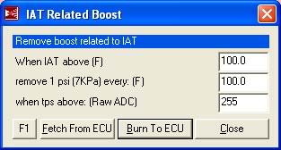
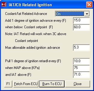
So, in both cases, some engine protection would seem to be in order. What we are protecting the engine against is high intake temperatures. These are the megasquirt areas that are going to give me that protection . . . :
Hey, it's a 182,000 mile short-nose 1.6. The way I see it, perfect for experimenting. I want a rebuild anyway.
There is some logic to this order, however. Having WI will let me get my IAT-related spark and boost decay values in one dyno tuning session. Note that these are good values to have whether you cool the intake charge with water or with an intercooler.
One thing to keep in mind with an intercooler is that it doesn't always cool the same. The intercooler's heat transfer mechanism is conduction. Thus, the main things that affect it are air flow and air temperature. It cools less going 25mph in 100�F air than it does going 70mph in 20�F air. So, less effective at the auto-X . . . great. Of course, the big plus is no moving parts -- reliability.
WI cooling (assuming that you aren't spraying so much water that it can't vaporize) will always remove the same amount of heat from the intake charge. The heat is removed by the phase change of the water -- and the heat removal is powerful. However, there are lots of parts here to go wrong.
So, in both cases, some engine protection would seem to be in order. What we are protecting the engine against is high intake temperatures. These are the megasquirt areas that are going to give me that protection . . . :
Hey, it's a 182,000 mile short-nose 1.6. The way I see it, perfect for experimenting. I want a rebuild anyway.
Hi!!
How did you arrive at these retard settings and did they work for you ?
Thanks
P
Reply
0
0
02-09-2013, 11:39 PM
#97
Elite Member
Thread Starter
iTrader: (4)
Join Date: Mar 2008
Location: Granbury, TX
Posts: 6,301
Total Cats: 696
Haven't been on this thread much. Been busy driving the heck out of the car. I've put 15,000 miles on it with the turbo. Recently, something happened . . . blown headgasket, cracked or warped block or head, something. Engine was making big clouds of steam from cylinder #4. I initially changed the head gasket, but that didn't fix it. Knowing that my crank nose was FUBAR anyway (although I must say, I'm impressed with the loctite fix), I went ahead and ordered one of these:
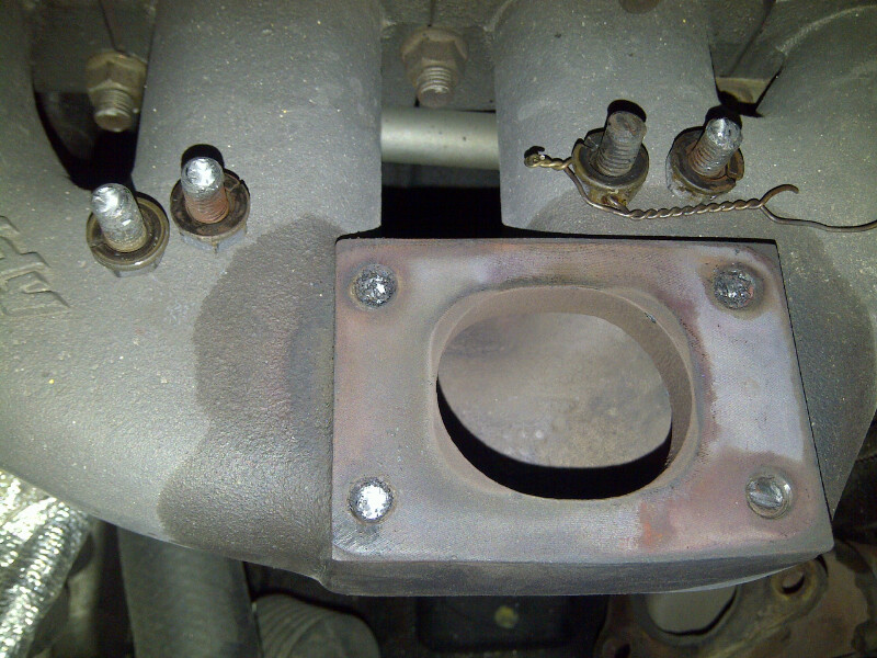
Tearing down to swap in the crate engine, I found more carnage than I expected. Turns out the turbo was loose, although the safety wire was holding everything together. The mild steel M8 manifold to turbo bolts had bad thermal creep. One was completely sheared. The other three sheared when I tried to unbolt the turbo:
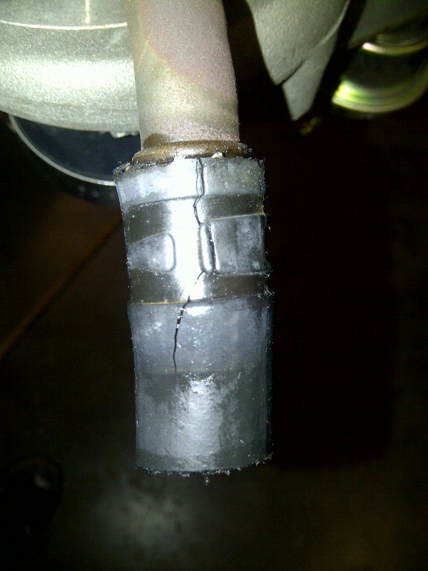
I also found that the turbo oil drain hose was completely cooked. Note that there isn't enough oil flowing through this hose to cool it. This is in contrast to the heater hoses that were still in great shape despite being almost as close to the exhaust manifold.
To fix the mess, here's what I did:
1. TSE M10 Inconel studs with Stage-8 locking hardware:
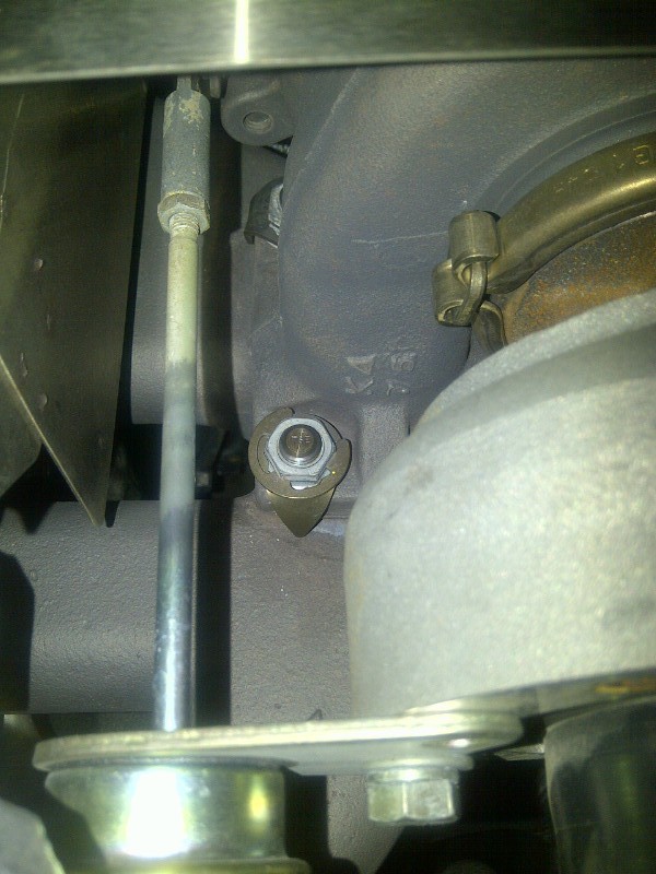
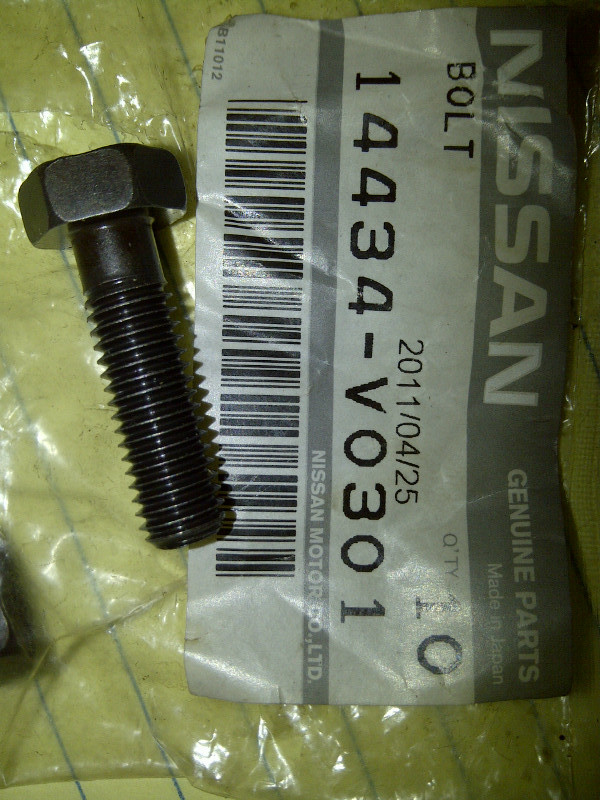
2. Since I went Inconel on the manifold to turbo, I decided to also do Inconel on the turbo to downpipe. This wasn't 100% needed since the original bolts in this location were still in decent shape, but I found some OEM Nissan Inconel bolts for cheap (about $3.50 each):
I drilled these bolts for Inconel safety wire just like the mild steel bolts. Inconel is harder to drill as it work-hardens, expect to use about 1 bit per bolt:
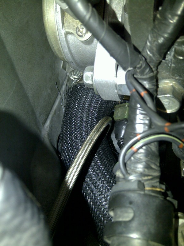
3. Went silicone on the turbo oil drain. This is the silicone hose with oil-resistant inner liner. We'll see if this holds up better to the heat:
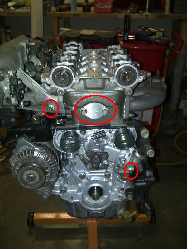
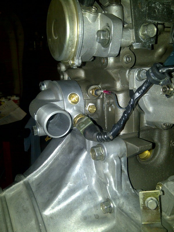
4. The cylinder that was getting water was #4. Since that cylinder is known to be the hottest in the absence of a coolant reroute, I felt it was time for the reroute. My reroute is similar to others, basically BEGI spacer, Kia waterneck, GM truck hose and front waterneck delete. Pictures:
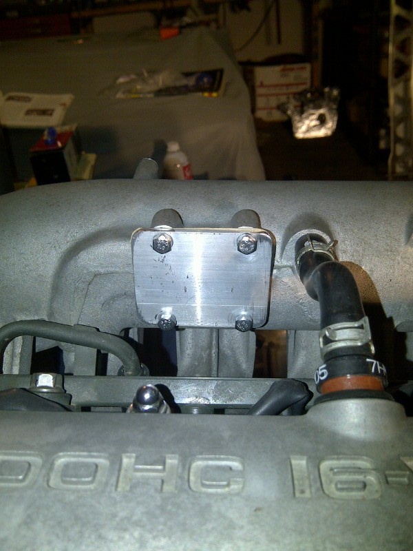
I deleted all of the little coolant hoses that run around the engine and blocked everything with pipe plugs. Here's the blocked-off air valve (just a piece of 2" x 1/8" aluminum stock from Home Depot with a cardboard gasket) -- there's been no change in cold-start driveability with the air valve delete:
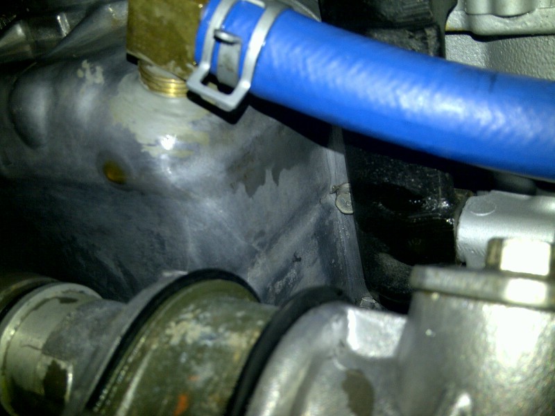
This picture shows the pipe plug at the front of the intake manifold, the TSE front waterneck block-off and the pipe plug at the little 90� tube on the waterpump inlet manifold (circled in red):
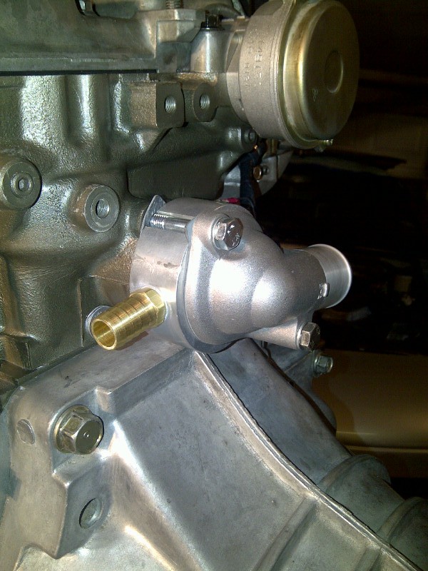
BEGI spacer pictures. Spacer is oriented for a 1.6L with stock crank angle sensor and coil packs. Note that the "cursed water plug" tube has been deleted in favor of a pipe plug:
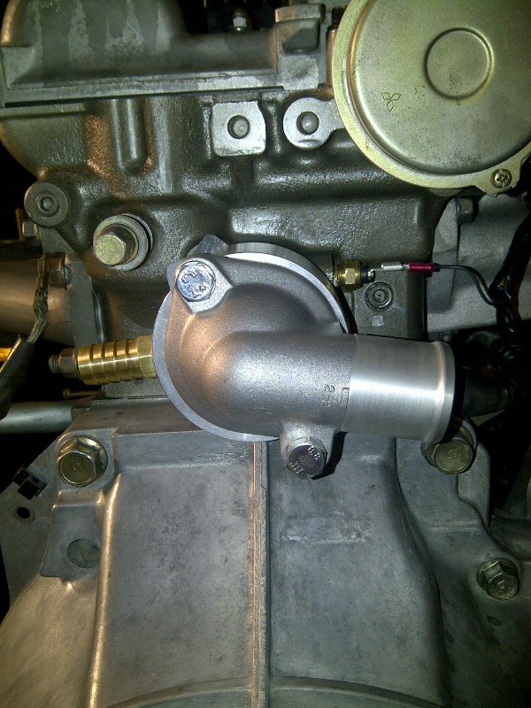
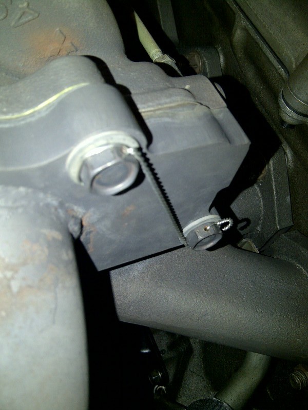
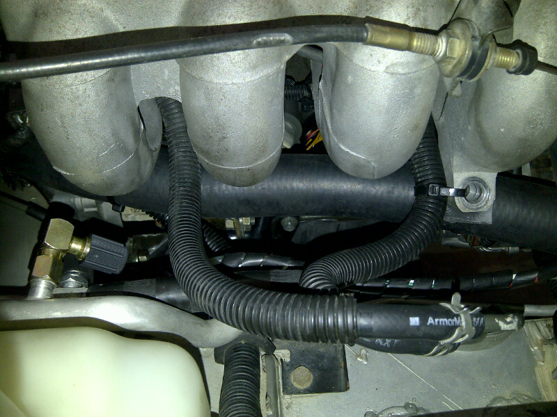
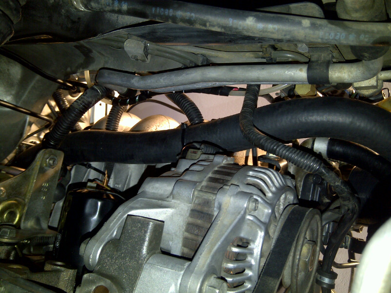
These pictures show the routing of the GM truck hose. I cut about 3.5" off the end at the back of the engine, and close to 5" off at the radiator end. The hose is secured to the intake manifold at the #1 and #4 runners. The hose came with some snakeskin that I positioned between the firewall and the flexible clutch line. Fit and chassis clearance were good and I don't expect chaffing. We'll see:
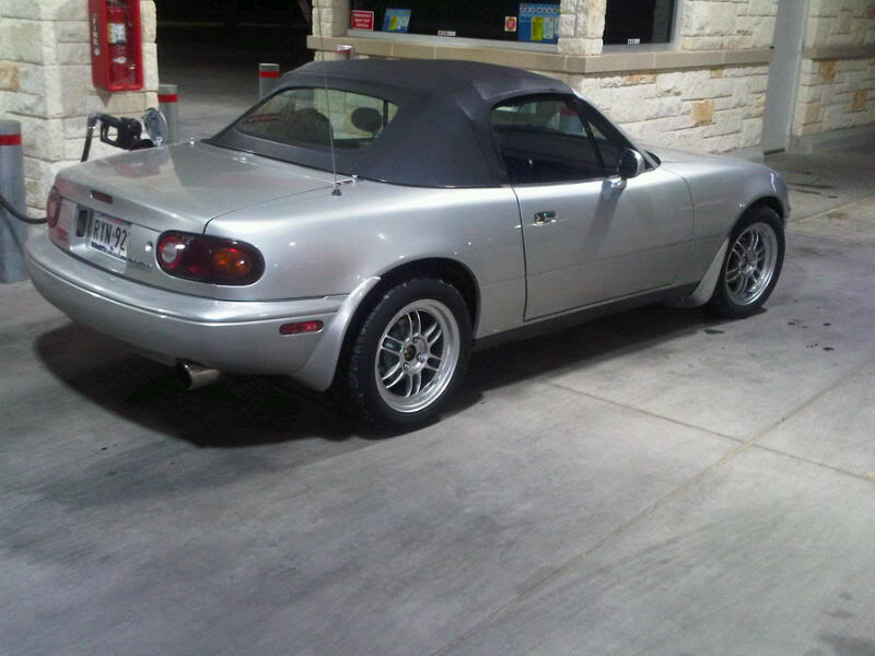
I'm about 350 miles into the break-in of the crate engine. So far, so good. Oh, and BTW, also got the FCM suspension mounted. It's really nice. Comfort and handling are both way up. Slammage glory shots:
Before:
After:
Tearing down to swap in the crate engine, I found more carnage than I expected. Turns out the turbo was loose, although the safety wire was holding everything together. The mild steel M8 manifold to turbo bolts had bad thermal creep. One was completely sheared. The other three sheared when I tried to unbolt the turbo:
I also found that the turbo oil drain hose was completely cooked. Note that there isn't enough oil flowing through this hose to cool it. This is in contrast to the heater hoses that were still in great shape despite being almost as close to the exhaust manifold.
To fix the mess, here's what I did:
1. TSE M10 Inconel studs with Stage-8 locking hardware:
2. Since I went Inconel on the manifold to turbo, I decided to also do Inconel on the turbo to downpipe. This wasn't 100% needed since the original bolts in this location were still in decent shape, but I found some OEM Nissan Inconel bolts for cheap (about $3.50 each):
I drilled these bolts for Inconel safety wire just like the mild steel bolts. Inconel is harder to drill as it work-hardens, expect to use about 1 bit per bolt:
3. Went silicone on the turbo oil drain. This is the silicone hose with oil-resistant inner liner. We'll see if this holds up better to the heat:
4. The cylinder that was getting water was #4. Since that cylinder is known to be the hottest in the absence of a coolant reroute, I felt it was time for the reroute. My reroute is similar to others, basically BEGI spacer, Kia waterneck, GM truck hose and front waterneck delete. Pictures:
I deleted all of the little coolant hoses that run around the engine and blocked everything with pipe plugs. Here's the blocked-off air valve (just a piece of 2" x 1/8" aluminum stock from Home Depot with a cardboard gasket) -- there's been no change in cold-start driveability with the air valve delete:
This picture shows the pipe plug at the front of the intake manifold, the TSE front waterneck block-off and the pipe plug at the little 90� tube on the waterpump inlet manifold (circled in red):
BEGI spacer pictures. Spacer is oriented for a 1.6L with stock crank angle sensor and coil packs. Note that the "cursed water plug" tube has been deleted in favor of a pipe plug:
These pictures show the routing of the GM truck hose. I cut about 3.5" off the end at the back of the engine, and close to 5" off at the radiator end. The hose is secured to the intake manifold at the #1 and #4 runners. The hose came with some snakeskin that I positioned between the firewall and the flexible clutch line. Fit and chassis clearance were good and I don't expect chaffing. We'll see:
I'm about 350 miles into the break-in of the crate engine. So far, so good. Oh, and BTW, also got the FCM suspension mounted. It's really nice. Comfort and handling are both way up. Slammage glory shots:
Before:
After:
Reply
0
0
02-14-2013, 09:36 AM
#99

Hornetball - making a Greddy based set up not look like a total POS.
I bought the TSE studs for my Greddy set up but have been questioning if the manifold had enough thickness - I'm assuming now that there was.
Since you're the safety wire pro, can you recommend any vendors who sell pre-drill nuts? I've got TSE studs for the turbo/manifold w/ stage 8 hardware so that should be good. For the turbo/downpipe I bought 8mm inconel studs from FM and nordlock washers, however, I'd like to safety wire as well.
Reply
0
0


