Ian's 99 build thread
 07-19-2016, 05:18 PM
#641
Elite Member

Thread Starter
Join Date: Mar 2007
Location: Santa Clara, CA
Posts: 5,165
Total Cats: 855
It's actually not all that complicated. With a manifold-referenced FPR, the fuel pressure is supposed to be equal to the manifold pressure plus a constant. So if I log both values, then subtract MAP from fuel pressure and graph the result, in an ideal world I would get a horizontal line with an X value equal to that constant. One reason why I don't is because the fuel pressure lags MAP (it's a mechanical system therefore it takes non-zero time for a change in one to create a change in the other). The lag changes show a characteristic shape on the graph, but if I ignore those ones there are still a few other places where the graph diverts from the ideal, and those are the ones I care about. By correlating the location of those shapes with the position data and lateral acceleration data in the log, I can see that they happen while powering out of fast left-hand corners -- ergo, fuel starvation under cornering loads.
--Ian
--Ian

Reply
 1
1

1
07-19-2016, 06:20 PM
#643
Elite Member

Join Date: Sep 2015
Location: San Jose, CA
Posts: 1,939
Total Cats: 117
It's actually not all that complicated. With a manifold-referenced FPR, the fuel pressure is supposed to be equal to the manifold pressure plus a constant. So if I log both values, then subtract MAP from fuel pressure and graph the result, in an ideal world I would get a horizontal line with an X value equal to that constant. One reason why I don't is because the fuel pressure lags MAP (it's a mechanical system therefore it takes non-zero time for a change in one to create a change in the other). The lag changes show a characteristic shape on the graph, but if I ignore those ones there are still a few other places where the graph diverts from the ideal, and those are the ones I care about. By correlating the location of those shapes with the position data and lateral acceleration data in the log, I can see that they happen while powering out of fast left-hand corners -- ergo, fuel starvation under cornering loads.
--Ian
--Ian
Reply
0
0
07-19-2016, 07:30 PM
#644
Elite Member
Thread Starter
Join Date: Mar 2007
Location: Santa Clara, CA
Posts: 5,165
Total Cats: 855
Fuel pressure is controlled by the fuel pressure regulator. The pump supplies fuel at a high pressure, and the FPR is a diaphragm and a spring arranged such that there is a set point pressure that the outlet pipe should be at, and any excess pressure is dumped into the "return" line and goes back to the tank. A manifold-referenced pressure regulator is one where you run a vacuum line to it from the tank so that instead of the FPR holding the outlet at a fixed pressure, it holds it at that fixed pressure plus whatever the pressure in the manifold is. In my case, that's around 32 psi (it's adjustable), meaning that the pressure in the fuel rail is always supposed to be 32 psi higher than the pressure in the manifold. Fuel pressure error is the difference between this theoretical ideal fuel pressure and the actual, measured fuel pressure.
Fuel pressure lags manifold pressure because the regulator is a mechanical system. In order for it to work, when the pressure in the manifold changes, air needs to travel down the vacuum line to the regulator, adjust the position of the diaphragm, and then the resulting additional pressure of fuel needs to travel back up the fuel line to the fuel rail. This takes a certain amount of time, and if you measure the manifold pressure & fuel pressure at a high enough sample rate, you can see that delay. Looking at my data, on my car this seems to take a few tenths of a second, that is the "lag".
So when I shift, the manifold pressure changes very rapidly from 200 kpa (15 psi of boost) to around 30 kpa (maximum vacuum) and then back to 200 kpa. By plotting fuel pressure error, I can see this lag as a spike a graph that is mostly a flat horizontal line. By putting that graph next to a graph of my throttle position sensor, I can see where the shifts happen, and I can identify the spikes caused by shifting. This leaves a few other bumps in the graph that are *not* caused by shifting, and those are what I'm worried about.
--Ian
Reply
2
2
07-19-2016, 09:35 PM
#645
Elite Member
Join Date: Sep 2015
Location: San Jose, CA
Posts: 1,939
Total Cats: 117
So MAP is "manifold absolute pressure", it's the air pressure in the intake manifold. At WOT in a naturally aspirated car, MAP is equal to ambient atmospheric pressure. At partial throttle, the manifold is in "vacuum", meaning the MAP is below ambient pressure, and in a turbo car in boost, MAP is higher than ambient pressure by some amount. "10 pounds of boost" means MAP is equal to ambient pressure (14.5 psi at sea level) plus 10 psi more from the turbo. You measure MAP with a MAP sensor, it's a little chip that you run a vacuum line to, pretty much every aftermarket ECU includes a MAP sensor because it's an integral part of the engine control logic.
Fuel pressure is controlled by the fuel pressure regulator. The pump supplies fuel at a high pressure, and the FPR is a diaphragm and a spring arranged such that there is a set point pressure that the outlet pipe should be at, and any excess pressure is dumped into the "return" line and goes back to the tank. A manifold-referenced pressure regulator is one where you run a vacuum line to it from the tank so that instead of the FPR holding the outlet at a fixed pressure, it holds it at that fixed pressure plus whatever the pressure in the manifold is. In my case, that's around 32 psi (it's adjustable), meaning that the pressure in the fuel rail is always supposed to be 32 psi higher than the pressure in the manifold. Fuel pressure error is the difference between this theoretical ideal fuel pressure and the actual, measured fuel pressure.
Fuel pressure lags manifold pressure because the regulator is a mechanical system. In order for it to work, when the pressure in the manifold changes, air needs to travel down the vacuum line to the regulator, adjust the position of the diaphragm, and then the resulting additional pressure of fuel needs to travel back up the fuel line to the fuel rail. This takes a certain amount of time, and if you measure the manifold pressure & fuel pressure at a high enough sample rate, you can see that delay. Looking at my data, on my car this seems to take a few tenths of a second, that is the "lag".
So when I shift, the manifold pressure changes very rapidly from 200 kpa (15 psi of boost) to around 30 kpa (maximum vacuum) and then back to 200 kpa. By plotting fuel pressure error, I can see this lag as a spike a graph that is mostly a flat horizontal line. By putting that graph next to a graph of my throttle position sensor, I can see where the shifts happen, and I can identify the spikes caused by shifting. This leaves a few other bumps in the graph that are *not* caused by shifting, and those are what I'm worried about.
--Ian
Reply
0
0
07-24-2016, 04:26 AM
#646
Elite Member
Thread Starter
Join Date: Mar 2007
Location: Santa Clara, CA
Posts: 5,165
Total Cats: 855
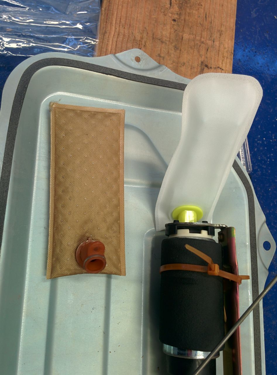
I bought a new fuel sock from Mazda, put it in today. Either they changed the design or the one that I had was the one that came with the Walbro. The Walbro (?) sock has non-rounded corners, is slightly longer, and lacks the metal springs that hold the OEM sock into a non-flat shape. New OEM sock in there now.
We experimented with tilting the car to try to simulate the the gee loading and see what the fuel in the tank did, but gave up when we realized that we'd need to go 6 feet in the air on one side to get the same angle as the car sees in turn 6 with the RRs on it. Yeah, not going to do that. At 16 degrees (equivalent of about .3 gees side load) the fuel didn't do much that was interesting. I'm really not sure I can reproduce the problem on the street, so I'll just have to see what happens at the next track day. Hopefully I can find another one to do before Miatas @ MRLS!
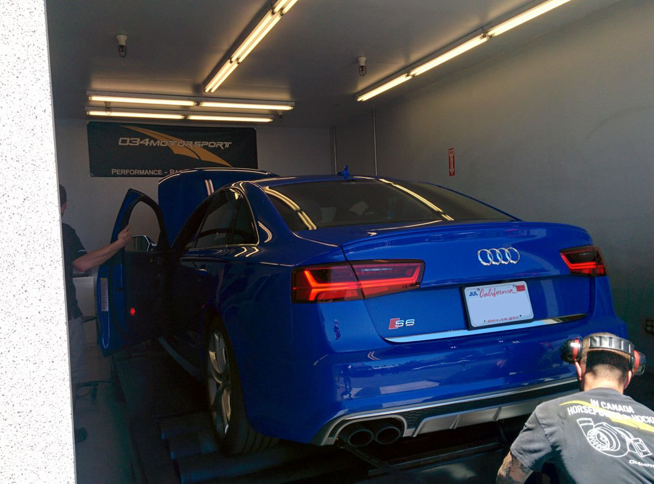
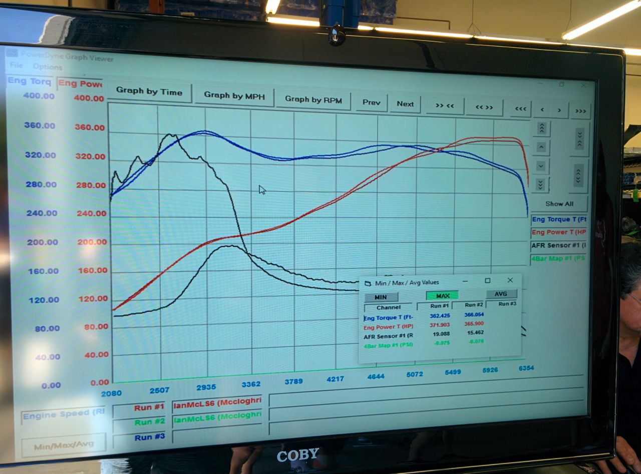
034Motorsport (an Audi shop in Fremont) had their annual open house/BBQ/dyno day today, so I took the S6 over there to see what it would do. The B6 S4 Avant did about 250 a few years ago (Nominally 340 at the crank, but it's a Mustang dyno, plus AWD losses), the S6 did 372. Yeah, this car is way faster than the S4 was.
--Ian
We experimented with tilting the car to try to simulate the the gee loading and see what the fuel in the tank did, but gave up when we realized that we'd need to go 6 feet in the air on one side to get the same angle as the car sees in turn 6 with the RRs on it. Yeah, not going to do that.
At 16 degrees (equivalent of about .3 gees side load) the fuel didn't do much that was interesting. I'm really not sure I can reproduce the problem on the street, so I'll just have to see what happens at the next track day. Hopefully I can find another one to do before Miatas @ MRLS!034Motorsport (an Audi shop in Fremont) had their annual open house/BBQ/dyno day today, so I took the S6 over there to see what it would do. The B6 S4 Avant did about 250 a few years ago (Nominally 340 at the crank, but it's a Mustang dyno, plus AWD losses), the S6 did 372. Yeah, this car is way faster than the S4 was.
--Ian
Reply
0
0
 07-24-2016, 02:28 PM
#648
Elite Member
Thread Starter
Join Date: Mar 2007
Location: Santa Clara, CA
Posts: 5,165
Total Cats: 855
--Ian
Reply
0
0
08-01-2016, 10:04 PM
#651
Newb

Join Date: Sep 2014
Posts: 21
Total Cats: 5
This weekend we added a new feature to the DashKitten (the Arduino-driven LCD dash): It now transmits its analog inputs back to the MegaSquirt.
We now need to find 6 more channels of data to log. We're considering: Oil pressure, fuel tank pressure, injector current, injector temperature, EGT, brake pressure.... Oops, we're out of inputs again.
Source code and instructions are here for anyone else who wants to try it: https://github.com/keepiru/dash-kitten
Reply
1
1
09-15-2016, 06:42 PM
#652
Elite Member
Thread Starter
Join Date: Mar 2007
Location: Santa Clara, CA
Posts: 5,165
Total Cats: 855
Hm, it's been a while since I posted here. Not all that much stuff happening on the Miata, although with MRLS in just about 2 weeks I need to make sure it's in good shape for that. I never did get a chance to validate that the new fuel sock fixed the pickup problems, so will just have to keep my fingers crossed. Worst case I'll just have to fill it up every session.
The truck is currently at the Chevy dealer getting new fuel injectors installed. Ouch. It's an LB7, the injectors are $400 each and they're buried under 13 hours' worth of labor. It's been smoking for a while (first sign of injector failure), but has recently started throwing codes and going into limp-home mode because it's unhappy with how the injectors are performing. That could be an electrical issue (code is for injector "shorted to ground"), or it could just be the failing injectors confusing it. Either way, time to replace them because I really don't want it going into limp-home-at-15-mph-and-4-cylinders mode while trying to pull the Miata up the hill at Laguna!
--Ian
Reply
0
0
09-15-2016, 08:06 PM
#655
Supporting Vendor

iTrader: (1)
Join Date: Sep 2010
Location: Lake Forest, CA
Posts: 7,947
Total Cats: 1,002
Keep more than 1/3 tank of fuel in it? Haven't done anything else. Edit: I'll be pulling it out and seeing if something's messed up. might go ahead and pull the soft top while I'm at it........
Reply
0
0
09-15-2016, 08:12 PM
#656
Elite Member
Thread Starter
Join Date: Mar 2007
Location: Santa Clara, CA
Posts: 5,165
Total Cats: 855
OK. I've turned on the MS3 "set the CEL when the parameters are out of whack" so hopefully I'll be able to notice if the car starts running lean coming out of left handers again. I'm also probably going to hack up the arduino to turn on one of the alarm LEDs if the fuel pressure goes out of range.
--Ian
--Ian
Reply
0
0

 09-19-2016, 07:44 PM
#658
Elite Member
Thread Starter
Join Date: Mar 2007
Location: Santa Clara, CA
Posts: 5,165
Total Cats: 855
So there's not a lot of Laguna prep required on my Miata, the last time I really drove it was at the GGLC Laguna Day in July (wow, was it really that long ago?) and the only problem it had was the fuel thing. I'm hoping that's fixed (if not I'm going to be buying gas a lot), so the only other prep is the immediate stuff like putting on the track tires & brakes, loading it on the trailer, etc. So TK and I spent a bunch of time on the Arduino project last weekend.
V1 of the Arduino worked pretty well, but had a couple problems. One was that it used an Arduino Uno, which only has 1 real serial port (used by the programmer) and only 2K of RAM. The LCD panel needs a serial input, we were using a big-banging SoftwareSerial library, and it worked OK for TX-only on a high-data rate port with relatively low utilization. The problem is that I'd like to have it receive data from the panel (for touch screen input) and also read the NMEA GPS data stream coming from the DL1, and those really aren't practical with SoftwareSerial. We were also running into stability problems because the heap would overflow the stack in some cases and crash it, due to lack of RAM.
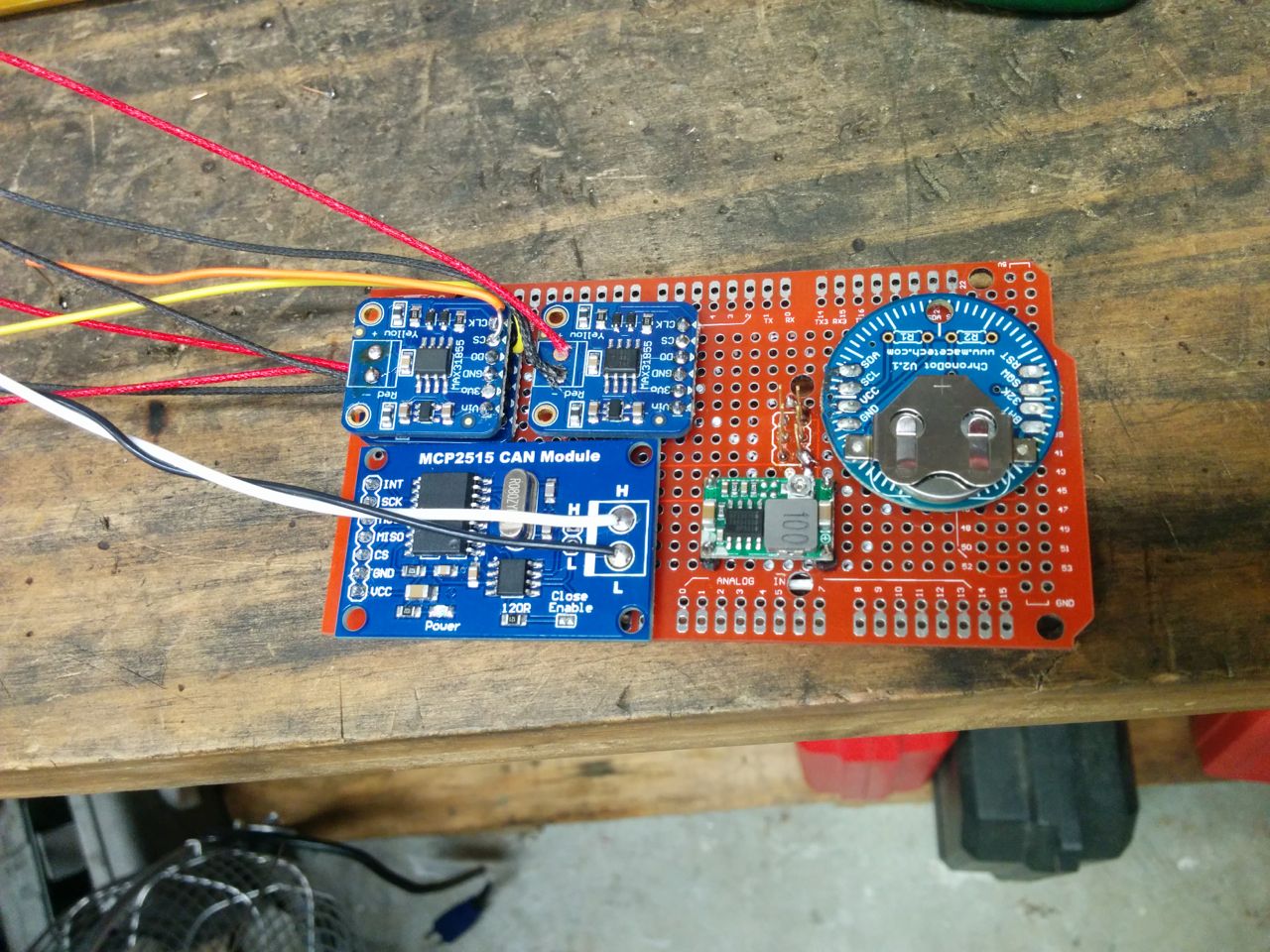
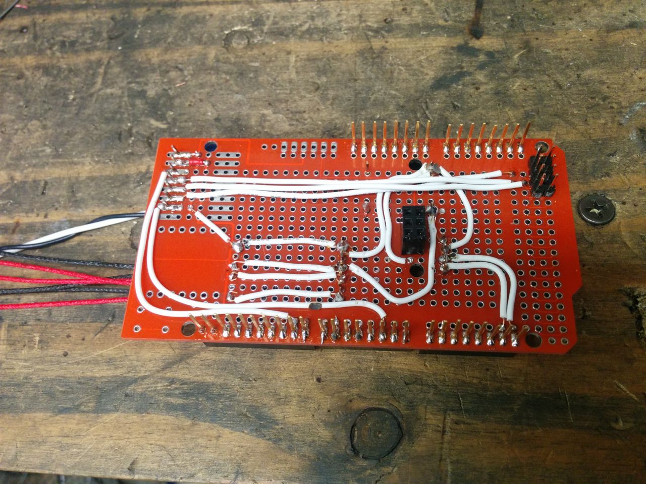
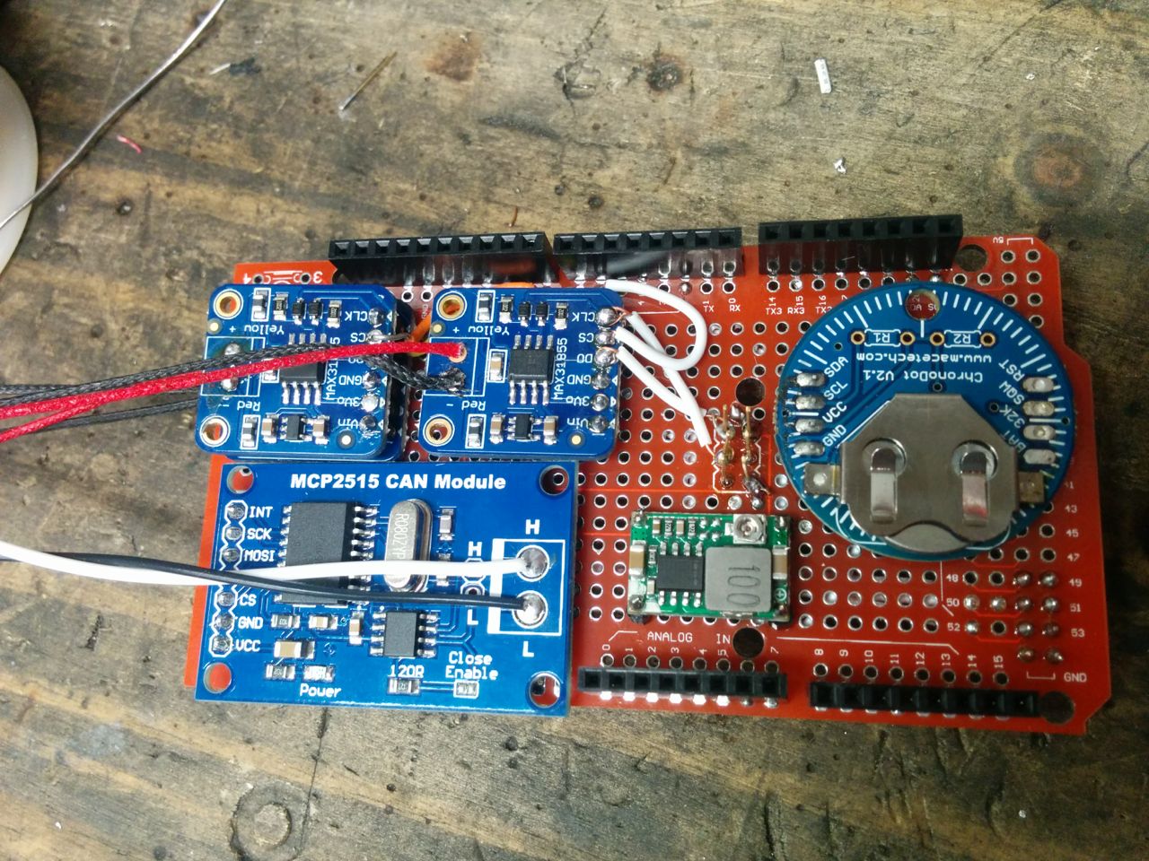
Fortunately, there's a bigger Arduino out there, the "Mega 2560". It's got 4 serial ports (1 for programming, 3 for general use), a whole bunch more ram, plus additional analog input pins that are nice-to-haves. It's pin-compatible, but didn't fit well inside the existing case because the 12v-to-5v power supply was taking up some of the space it wanted to live in. Additionally, we wanted to add some more functionality to the Arduino in the form of thermocouple driver chips and an RTC, and to fit that in the case meant that I needed to lose the CAN bus shield and replace it with a more compact CAN bus module.
So, I picked up a Mega-sized protoshield as well as a CAN bus module, 3 thermocouple modules, an RTC module, and a more compact power supply. With much soldering instruction from TK (along with him bailing me out when I globbed on too much solder bridging pins and the like), I wound up with this:
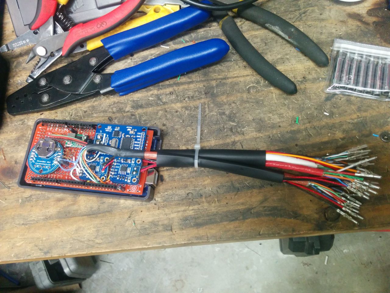
Then it goes in the case and gets an absurd number of wires coming out. It's using a 36-pin molex .062 connector, and will probably need a second one if I'm going to hook up all three thermocouples.
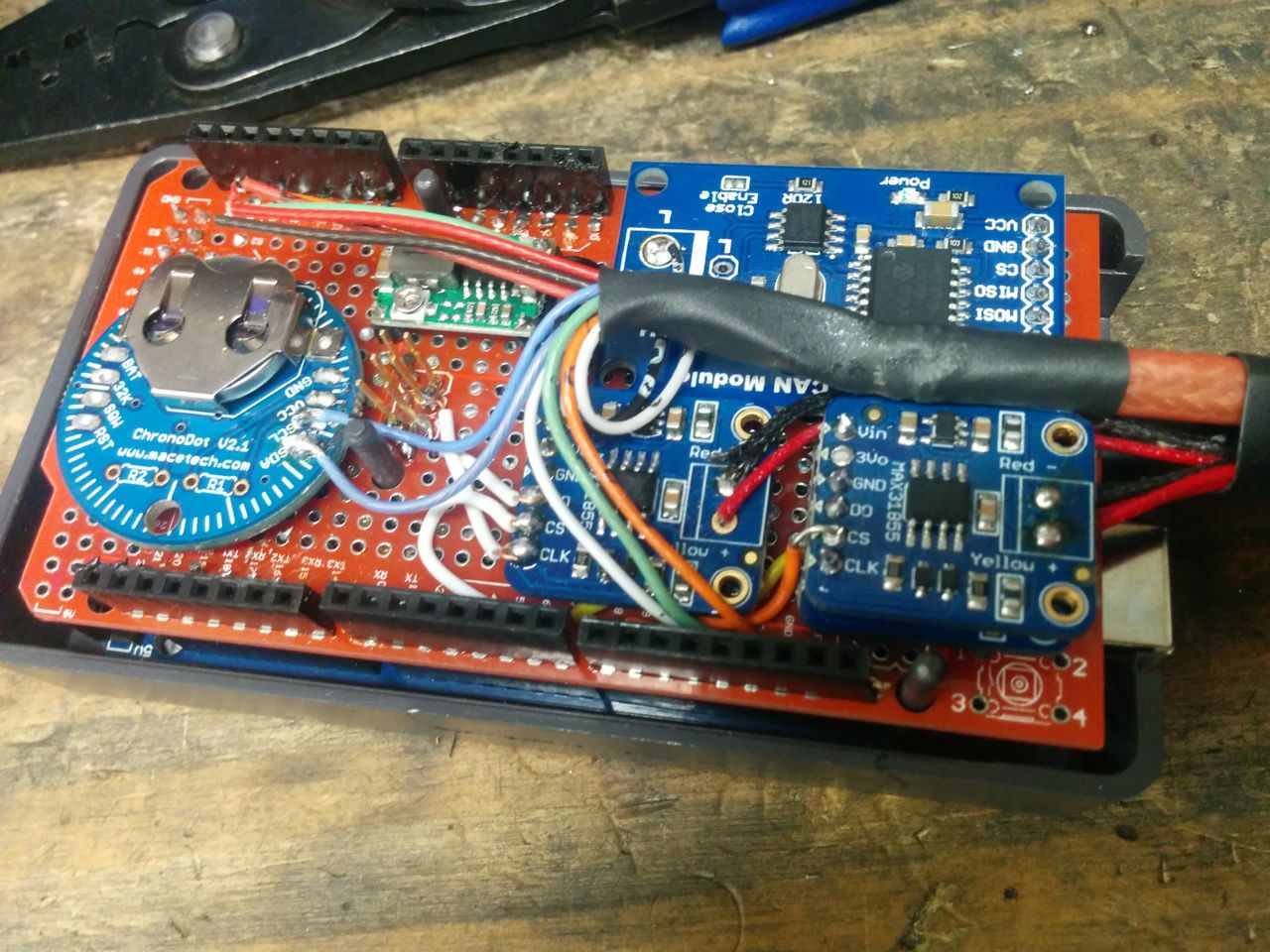
...and it works! Lots of software work to do on it, though. It's syncing the RTC to the MS3 over CAN bus, but the thermocouples aren't hooked up to anything yet. One of them will be EGT. Currently I have an AutoMeter EGT gauge installed, but it's not working because the insulation melted on the probe wire above the exhaust manifold. Even if it was working, the AutoMeter isn't set up to play nicely with others, there's no way to share the EGT sender thermocouple between the AutoMeter and the Arduino. So what's probably going to happen is that I'll replace the sender, ditch the AutoMeter, read the EGT with the Arduino, and just put some kind of display device in the A-pillar pod that's currently holding the AutoMeter for the Arduino to drive.
The second thermocouple is for monitoring the fuel rail temperature, that's for collecting data to try to figure out a good solution for the "car runs lean on hot restart because dead time has gotten longer" problem. The third is just because I had ordered an extra module by mistake, so why not hook it up.
(And yes, the thermocouples look like they're wired backwards. They're not, that's just because the cheap Chinese thermocouple wire I bought from Amazon uses red + black instead of yellow + red, even though it's type K.)
--Ian
V1 of the Arduino worked pretty well, but had a couple problems. One was that it used an Arduino Uno, which only has 1 real serial port (used by the programmer) and only 2K of RAM. The LCD panel needs a serial input, we were using a big-banging SoftwareSerial library, and it worked OK for TX-only on a high-data rate port with relatively low utilization. The problem is that I'd like to have it receive data from the panel (for touch screen input) and also read the NMEA GPS data stream coming from the DL1, and those really aren't practical with SoftwareSerial. We were also running into stability problems because the heap would overflow the stack in some cases and crash it, due to lack of RAM.
Fortunately, there's a bigger Arduino out there, the "Mega 2560". It's got 4 serial ports (1 for programming, 3 for general use), a whole bunch more ram, plus additional analog input pins that are nice-to-haves. It's pin-compatible, but didn't fit well inside the existing case because the 12v-to-5v power supply was taking up some of the space it wanted to live in. Additionally, we wanted to add some more functionality to the Arduino in the form of thermocouple driver chips and an RTC, and to fit that in the case meant that I needed to lose the CAN bus shield and replace it with a more compact CAN bus module.
So, I picked up a Mega-sized protoshield as well as a CAN bus module, 3 thermocouple modules, an RTC module, and a more compact power supply. With much soldering instruction from TK (along with him bailing me out when I globbed on too much solder bridging pins and the like), I wound up with this:
Then it goes in the case and gets an absurd number of wires coming out. It's using a 36-pin molex .062 connector, and will probably need a second one if I'm going to hook up all three thermocouples.
...and it works! Lots of software work to do on it, though. It's syncing the RTC to the MS3 over CAN bus, but the thermocouples aren't hooked up to anything yet. One of them will be EGT. Currently I have an AutoMeter EGT gauge installed, but it's not working because the insulation melted on the probe wire above the exhaust manifold. Even if it was working, the AutoMeter isn't set up to play nicely with others, there's no way to share the EGT sender thermocouple between the AutoMeter and the Arduino. So what's probably going to happen is that I'll replace the sender, ditch the AutoMeter, read the EGT with the Arduino, and just put some kind of display device in the A-pillar pod that's currently holding the AutoMeter for the Arduino to drive.
The second thermocouple is for monitoring the fuel rail temperature, that's for collecting data to try to figure out a good solution for the "car runs lean on hot restart because dead time has gotten longer" problem. The third is just because I had ordered an extra module by mistake, so why not hook it up.
(And yes, the thermocouples look like they're wired backwards. They're not, that's just because the cheap Chinese thermocouple wire I bought from Amazon uses red + black instead of yellow + red, even though it's type K.)
--Ian
Reply
1
1
09-21-2016, 03:50 AM
#660
Elite Member
Thread Starter
Join Date: Mar 2007
Location: Santa Clara, CA
Posts: 5,165
Total Cats: 855
The same things the other one did, only better. Basically:
- Listen to the data that the MS3 sends out on CAN bus and display it on the LCD dash
- Read the real-time clock and send the time back to the MS3 over CAN bus (the RTC that is on-board on my MS3 is broken)
- Monitor analog inputs and send the values that it records there back to the MS3 over CAN bus, where the MS3 can input them as generic sensors and log them. I'm planning on reading the narrowband HEGO this way, and I'm curious to see what the fuel tank pressure sensor indicates. Also oil temperature and oil pressure.
- Monitor the thermocouple driver chips to read temperatures from places I put thermocouples. EGT is one primary use of this, plus I want to monitor fuel rail temperature to try to address some hot restart issues that I'm seeing.
- I plan to interface it to the data logging serial port on the RaceLogic Traction Control unit so that I can add the wheel speed and TC activation data to the logs that I already have.
Much of this is stuff I could do in the MS3 natively or with one of the pre-built MS3 IO expansion units, but by DIYing it in my own Arduino I have much greater control over it.
--Ian
Basically:- Listen to the data that the MS3 sends out on CAN bus and display it on the LCD dash
- Read the real-time clock and send the time back to the MS3 over CAN bus (the RTC that is on-board on my MS3 is broken)
- Monitor analog inputs and send the values that it records there back to the MS3 over CAN bus, where the MS3 can input them as generic sensors and log them. I'm planning on reading the narrowband HEGO this way, and I'm curious to see what the fuel tank pressure sensor indicates. Also oil temperature and oil pressure.
- Monitor the thermocouple driver chips to read temperatures from places I put thermocouples. EGT is one primary use of this, plus I want to monitor fuel rail temperature to try to address some hot restart issues that I'm seeing.
- I plan to interface it to the data logging serial port on the RaceLogic Traction Control unit so that I can add the wheel speed and TC activation data to the logs that I already have.
Much of this is stuff I could do in the MS3 natively or with one of the pre-built MS3 IO expansion units, but by DIYing it in my own Arduino I have much greater control over it.
--Ian
Reply
0
0


