NiklasFalk slow N/A VVT build
 06-04-2013, 08:21 AM
#1
Senior Member
Thread Starter
iTrader: (1)

Join Date: Jun 2006
Location: Sweden
Posts: 1,391
Total Cats: 63
This have been going on for so long it's starting to feel like a constant change going nowhere. And it's time to consolidate my issues in one thread.
The car is a NB which started it live as a one-make race car built in Belgium for the Mazda Belgium 20 year anniversary.
It's a EU 99 taken directly form the boat to Kronos Racing which made very minor modification to the chassis (hopelessly stiff Bilsteins and 90/50 N/mm springs) and added a cage.
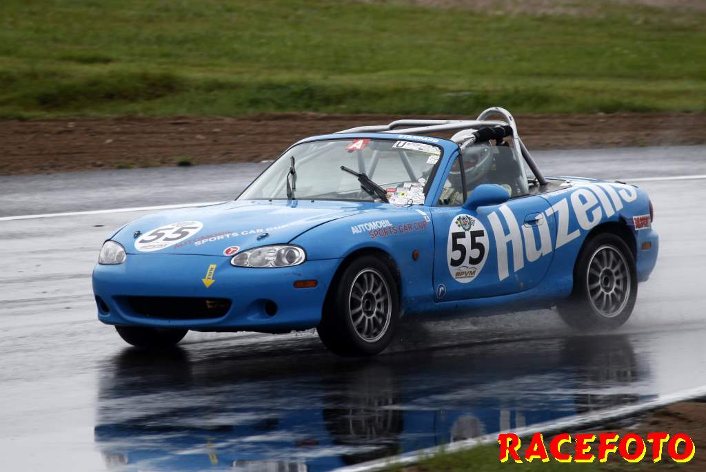
When i got hold of it in 2005 the odo read 8700km (5400 mi), track only, so it was just run in.
The stock engine served me well during the 2006-2010 seasons (just about 8 hours of track time per season) but in the Autumn of 2010 I got a VVT engine which I planned to get the most out of to move up a class.
I added a DIYPNP for the 2010 season https://www.miataturbo.net/megasquir...estions-48516/ to enable future enhancements.
The rules (written partly by myself) use levels of weight/hp and the power is either estimated based on stock spec or calculated using an empiric formula and some tables.
For me 1883cc and 7500rpm would be calculated as 195 bhp giving 1065kg (2348 lbs) min weight including driver (7kg/bhk, 5% extra for ABS), which is exactly where I'm at with close to empty tank.
If someone want to get a brain freeze the formula (for 4valve injected engines) is: 14.5 * ((Volume-1.1)*0.92+1.1) * ((MaxKRpm-6.9)*0.79+6.9) * (MaxBar * 0.6 + 1) = predicted bhp
For the 2011 season the plan was to port the head with +1mm intake valves, MS SUBs and run with the stock 10:1 pistons and stock cams.
The chambers were balanced at 52.5cc (not much unshrouding)
The flow values are at 10" water, CFM wet air followed by dry air.
After three race hours a lash cap collapsed (at 7300rpm), then the retainer split, followed by the valve dropping be snapped by the piston

https://www.miataturbo.net/engine-pe...28/#post885540
After this the old trusted unopened engine went back again and the full VVT build started.
The whole 2012 was run on the old engine due to waiting on all small parts that I continuously forgot to order (gaskets, o-rings, piston rings etc etc).
When I got the engine in October 2012 the energy was not there to get it done so it was sitting in the engine bay until late April.
When I was ready to start it up using the same settings as when the valve dropped (same intake, same exhaust, same injectors) it sputtered and was only able to get started on three cylinders once.
https://www.miataturbo.net/engine-pe...roblems-72724/
After verifying all (so I though) mechanical things I started to wonder about the decoding
https://www.miataturbo.net/megasquir...ng-work-72830/
But that was also OK.
Then i started to verify the builders work, trying to trace things backwards, and one intake valve on no3 had zero lash. Being unsure of my measuring method I did not think that much about it at first.
Missing out on the first race of the year I got some inspiration (while assisting an a number of late night teardown/rebuilds of heads and gearboxes).
So i strapped the belt onto the wheels, loosened the cam belt adjuster and pulled the intake cam and there it was, the suspected lifter sitting 2-3 mm higher than the rest.
Lifting the bucket and putting the lash cap back in place made everything as it should be (lash of about 0.2mm as all the other valves).
While it was sputtering on three cylinders I noticed the vacuum at 70kpa, which made me investigate Alpha-N (obvious but...).
After a couple of attempts I was able to get it started and also get a raised idle of 1800rpm, time for break in.
Breaking it in worked, but the idle was crap when warm (kind of disturbing in traffic) and it starts to get "on cam" at 5000rpm. Final max vacuum became about 60kpa at 2000 rpm, too little for MAP control and the VVTuner can work with load independent advance (pulling from low rpm will probably suffer if the whole low-rpm columns look like idle/startup values).
All starup and break-in was done with the VVT OCV disconnected, how it will handle the tougher ST springs will be interesting (others have probably done the exercise, but I have not found any reports).
Track time possible on Friday, more mapping (preferably all the way to 8000rpm) before then, it's not raining at least.
Dyno time sometime during the summer, maybe.
The Jenveys will have to wait since there isn't space and it require change to throttle placed injectors (the connectors collide with the flange), proper airbox, ...
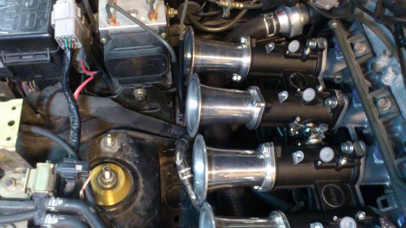
Longer intake, shorter throttle bodies and curved trumpets would be a better solution, meaning selling off every part of the current Jenvey kit...
The car is a NB which started it live as a one-make race car built in Belgium for the Mazda Belgium 20 year anniversary.
It's a EU 99 taken directly form the boat to Kronos Racing which made very minor modification to the chassis (hopelessly stiff Bilsteins and 90/50 N/mm springs) and added a cage.
When i got hold of it in 2005 the odo read 8700km (5400 mi), track only, so it was just run in.
The stock engine served me well during the 2006-2010 seasons (just about 8 hours of track time per season) but in the Autumn of 2010 I got a VVT engine which I planned to get the most out of to move up a class.
I added a DIYPNP for the 2010 season https://www.miataturbo.net/megasquir...estions-48516/ to enable future enhancements.
The rules (written partly by myself) use levels of weight/hp and the power is either estimated based on stock spec or calculated using an empiric formula and some tables.
For me 1883cc and 7500rpm would be calculated as 195 bhp giving 1065kg (2348 lbs) min weight including driver (7kg/bhk, 5% extra for ABS), which is exactly where I'm at with close to empty tank.
If someone want to get a brain freeze the formula (for 4valve injected engines) is: 14.5 * ((Volume-1.1)*0.92+1.1) * ((MaxKRpm-6.9)*0.79+6.9) * (MaxBar * 0.6 + 1) = predicted bhp
For the 2011 season the plan was to port the head with +1mm intake valves, MS SUBs and run with the stock 10:1 pistons and stock cams.
The chambers were balanced at 52.5cc (not much unshrouding)
The flow values are at 10" water, CFM wet air followed by dry air.
Code:
Intake Port Original   Intake 34.0mm
 1.0mm   16.2  16.4     19.7  20.0
 2.0mm   35.7  36.3     41.0  41.7
 3.0mm   51.4  52.2     59.3  60.2
 4.0mm   69.8  71.0     75.3  76.6
 5.0mm   84.8  86.2     91.1  92.6
 6.0mm   99.6 101.3    105.6 107.3
 7.0mm  108.8 110.6    117.1 119.1
 8.0mm  114.9 116.8    126.2 128.2
 9.0mm  118.1 120.1    133.2 135.4
10.0mm  120.7 122.7    138.0 140.3
11.0mm  122.3 124.3    141.7 144.0
12.0mm  121.4 123.4    145.0 147.4
13.0mm  121.5 123.5    145.6 148.0

Exhaust Port Original  Exhaust ported
 1.0mm   12.5  12.7     12.5  12.7
 2.0mm   27.0  27.5     29.3  29.8
 3.0mm   44.3  45.0     48.0  48.8
 4.0mm   60.5  61.5     65.1  66.2
 5.0mm   77.8  79.1     82.5  83.9
 6.0mm   89.8  91.2     92.2  93.8
 7.0mm   95.9  97.5     98.0  99.7
 8.0mm   99.1 100.7    102.8 104.5
 9.0mm  100.9 102.     105.7 107.5
10.0mm  102.7 104.4    109.9 111.8
11.0mm  104.1 105.8    113.3 115.2
12.0mm  105.2 107.0    115.9 117.8
13.0mm                 118.2 120.2
https://www.miataturbo.net/engine-pe...28/#post885540
After this the old trusted unopened engine went back again and the full VVT build started.
The whole 2012 was run on the old engine due to waiting on all small parts that I continuously forgot to order (gaskets, o-rings, piston rings etc etc).
When I got the engine in October 2012 the energy was not there to get it done so it was sitting in the engine bay until late April.
When I was ready to start it up using the same settings as when the valve dropped (same intake, same exhaust, same injectors) it sputtered and was only able to get started on three cylinders once.
https://www.miataturbo.net/engine-pe...roblems-72724/
After verifying all (so I though) mechanical things I started to wonder about the decoding
https://www.miataturbo.net/megasquir...ng-work-72830/
But that was also OK.
Then i started to verify the builders work, trying to trace things backwards, and one intake valve on no3 had zero lash. Being unsure of my measuring method I did not think that much about it at first.
Missing out on the first race of the year I got some inspiration (while assisting an a number of late night teardown/rebuilds of heads and gearboxes).
So i strapped the belt onto the wheels, loosened the cam belt adjuster and pulled the intake cam and there it was, the suspected lifter sitting 2-3 mm higher than the rest.
Lifting the bucket and putting the lash cap back in place made everything as it should be (lash of about 0.2mm as all the other valves).
While it was sputtering on three cylinders I noticed the vacuum at 70kpa, which made me investigate Alpha-N (obvious but...).
After a couple of attempts I was able to get it started and also get a raised idle of 1800rpm, time for break in.
Breaking it in worked, but the idle was crap when warm (kind of disturbing in traffic) and it starts to get "on cam" at 5000rpm. Final max vacuum became about 60kpa at 2000 rpm, too little for MAP control and the VVTuner can work with load independent advance (pulling from low rpm will probably suffer if the whole low-rpm columns look like idle/startup values).
All starup and break-in was done with the VVT OCV disconnected, how it will handle the tougher ST springs will be interesting (others have probably done the exercise, but I have not found any reports).
Track time possible on Friday, more mapping (preferably all the way to 8000rpm) before then, it's not raining at least.
Dyno time sometime during the summer, maybe.
The Jenveys will have to wait since there isn't space and it require change to throttle placed injectors (the connectors collide with the flange), proper airbox, ...
Longer intake, shorter throttle bodies and curved trumpets would be a better solution, meaning selling off every part of the current Jenvey kit...
Last edited by NiklasFalk; 06-16-2013 at 08:54 AM.

Reply
 0
0

0
06-05-2013, 01:42 PM
#2
Senior Member
Thread Starter
iTrader: (1)
Join Date: Jun 2006
Location: Sweden
Posts: 1,391
Total Cats: 63
So I now know two things (building up to this test for close to two years...);
1. the VVT control seems safe when the oil pressure is low (cam drags on the retarted side of course when i think about it)
2. It can reach it's target even when using the stiffer ST dual springs and 10.7mm lift.
The -13 degrees as lock position can be due to two reasons;
1. the block is decked enough to move everything one tooth.
2. the nub ring at the back of the cam doen't have any directing marks so it's placed bye eye when moved from the OEM cam.
If 13 degrees advanced from "zero" is too much we will move the nub ring when I get on a dyno.
VVTuner does not seem to be happy with negative values in the table (at least not on my firmware).
Happy days doing a mapping run tomorrow
 . The idle is much more rumpy-dumpy with "13" degrees advance, lets hope it's peppier before 5kprm too.
Track testing on Friday is still a possibility...
Reply
0
0
06-06-2013, 08:21 AM
#3
Senior Member
Thread Starter
iTrader: (1)
Join Date: Jun 2006
Location: Sweden
Posts: 1,391
Total Cats: 63
Sweet smooth runs, and it's scary fast on small roads (pulling 4th to 8k will not happen).
I will get used to it though, but I had forgot how hard the AWR engine mounts are (engine is much better balanced now but it's a dentist experience above 5krpm).
Going back to zero advance at about 6k (5 degrees advance from 2k-4k and then ramp to zero) seems to loose some pull (not as peppy 7-8), so there is some playing to be done (with AutoTune blue/red cells as a guidance before going to a Rototest, sometime).
Only a small leak from one of the hose connectors to the newly installed oil cooler to fix before I go out on the next session of the day.
This is FUN!
Reply
0
0
06-15-2013, 03:38 PM
#4
Senior Member
Thread Starter
iTrader: (1)
Join Date: Jun 2006
Location: Sweden
Posts: 1,391
Total Cats: 63
Changed to RX8 Yellow injectors and took it for a small adjustment run.
Calculating a new Req Fuel and scaling the VE table (to get the high values at about 215 to gain resolution) worked like a charm.
But now I noticed that the Alternator control needs checking. 19V is not a good thing
The RX8 yellows was a good choice since I use 56% DC.
The CLT spike a bit high for comfort. A new Rad is ordered, and there is plenty of cardboard and duct tape in the front.
Wonder how it would behave with longer punishment (no planned trackday until next race in July)?
A better timing map would of course lower the temps.
Reply
0
0
06-16-2013, 08:22 AM
#5
Senior Member
Thread Starter
iTrader: (1)
Join Date: Jun 2006
Location: Sweden
Posts: 1,391
Total Cats: 63
Hmm, on the bench, my Alt control circuit does exactly what it should; Field-Out connected to 1O follows V-in util it reaches 14.2V then it goes to zero.
I have replaced my alternator due to the stock one buring the diodes (no logs of the voltage then).
Could it be that my current Alt is not happy with the control being on 1O?
The Alt worked fine when compled with the Mazda ECU (no charge light, but I don't know what voltage was back then either.
Worth testing Field-Out on 1T, of should I add a pulldown resistor (since the voltage meter (Fluke) did not show 0V, it showed floating as with no connection to ground)?
Uploaded my scheme of the JC alternator Control (<2010 design) since my old lik is not waoking anymore
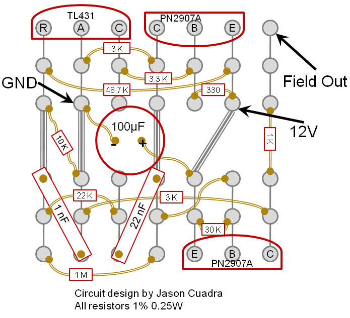
And no, all resistors don't have to be 1% but I forgot which ones, and I only have 1%.
Edit: Scrap the part of floating output, brain-fart when reading the multimeter (which have a display delay when the output change a lot in a short time).
Maybe a flawed alternator, I'll have to verify and then visit the Alternator shop tomorrow (I have OEM one which need new diodes anyway).
I have replaced my alternator due to the stock one buring the diodes (no logs of the voltage then).
Could it be that my current Alt is not happy with the control being on 1O?
The Alt worked fine when compled with the Mazda ECU (no charge light, but I don't know what voltage was back then either.
Worth testing Field-Out on 1T, of should I add a pulldown resistor (since the voltage meter (Fluke) did not show 0V, it showed floating as with no connection to ground)?
Uploaded my scheme of the JC alternator Control (<2010 design) since my old lik is not waoking anymore
And no, all resistors don't have to be 1% but I forgot which ones, and I only have 1%.
Edit: Scrap the part of floating output, brain-fart when reading the multimeter (which have a display delay when the output change a lot in a short time).
Maybe a flawed alternator, I'll have to verify and then visit the Alternator shop tomorrow (I have OEM one which need new diodes anyway).
Last edited by NiklasFalk; 06-16-2013 at 11:19 AM.
Reply
0
0
06-16-2013, 01:21 PM
#6
Senior Member
Thread Starter
iTrader: (1)
Join Date: Jun 2006
Location: Sweden
Posts: 1,391
Total Cats: 63
Maybe the poor control only happens when warmed up.
Oh how fun it is with unreproducible problems (or difficulty to recreate the situation at any time)
Reply
0
0
06-17-2013, 04:32 AM
#7
Senior Member
Thread Starter
iTrader: (1)
Join Date: Jun 2006
Location: Sweden
Posts: 1,391
Total Cats: 63
The alt was flawed, shown as shorted on the test bench.
This after about 5 hours of service since last August, when i replaced the burned out OEM one. Might get a replacement/repair as warranty job.
Just bad luck or is the home grown alt control frying the alternators?
Can the Field-Out be connected to any of DIYPNP inputs to be able to log it's action (unsure if I have any inputs free though)?
Reply
0
0
06-17-2013, 02:01 PM
#8
Boost Czar


iTrader: (62)
Join Date: May 2005
Location: Chantilly, VA
Posts: 79,493
Total Cats: 4,080
there's no load on field-out, it's just a signal to tell the alt to either charge or not. When properly built using +/-1% resistors, that circuit should keep it at 14.2v regardless.
you can input it only if you send it back to a relay that sends a ground to a spare input on the ecu.
you can input it only if you send it back to a relay that sends a ground to a spare input on the ecu.
Reply
0
0
06-27-2013, 08:28 AM
#9
Senior Member
Thread Starter
iTrader: (1)
Join Date: Jun 2006
Location: Sweden
Posts: 1,391
Total Cats: 63
Went to a Rototest yesterday to get some verification how a half-asses setup (Squaretop) can perform until I take the dive into cleaning up the engine bay for the Jenveys.
This will trigger some head-scratching and laughs (we have theories).
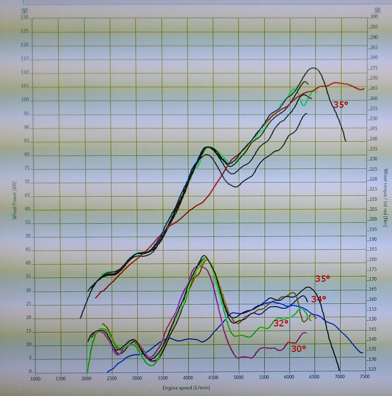
Just a photo, and with the wrong numbers (since we didn't correct the final ratio from 1:4.3 to 1:4.875), the final sweep is to 8200.
The trend is clear and that we got the best result with nothing attached to the Throttle Body (even a better low end) tells us there are improvements to be made in the air supply (a Trubo of course, but not with this CR and duration).
The Red/blue lines is a standard 99 for comparison.
The theory is that 305 duration does not play well at all with the Squaretop.
The spitback is so bad that a very short tube is needed to get rid of it.
Leaning it out a bit might help as well (it flickers down to 11.5 AFR at some places in the sweep).
Changing the VVT only changed things up to the torque peak, after that it fell flat regardless of -13 (disconnected), 0, 5, 10, 14 degrees advance.
The plan for next weekends race is to build a large filtered volume in form to the TB and attaching a flared end to the TB (with the flare sticking into the filtered volume). The I have one month to try to move the fuel lines, the ABS etc to clear as much space as possible for an airbox around the Jenveys.
Another result was that the CR of 11.8:1 is too low for the cams/overlap 12.5:1 would be better. The analysis here is based on the fact that it responds to ignition change from 34 to 35�, it should not need more than 30-32.
The head flows as well as a 280bhp 2.0L BDG so there is no problem running that compression.
Custom pistons during the winter would be nice if it fits the budget after the season.
The main problem is the intake, this is a real case where ITB isn't just a few percentage at the top, here they are really needed to make the damn thing to work at all.
First hours at a dyno and I really learned a lot.
Setting up the Rototest is easy.
I would love to know if it's possible to get sweeps automatically logged/reported in TunerStudio (store datalogs where you sweep from 2500 to 7500 in under 20 secs)?
I edited out the last pulls from the datalog.
A new alternator did not help, the reported voltage goes up to 19V.
Interestingly the VVTuner reports max 16.4V...
Could this be poor grounding or something, which also would affect AFRs etc etc?
This will trigger some head-scratching and laughs (we have theories).
Just a photo, and with the wrong numbers (since we didn't correct the final ratio from 1:4.3 to 1:4.875), the final sweep is to 8200.
The trend is clear and that we got the best result with nothing attached to the Throttle Body (even a better low end) tells us there are improvements to be made in the air supply (a Trubo of course, but not with this CR and duration).
The Red/blue lines is a standard 99 for comparison.
The theory is that 305 duration does not play well at all with the Squaretop.
The spitback is so bad that a very short tube is needed to get rid of it.
Leaning it out a bit might help as well (it flickers down to 11.5 AFR at some places in the sweep).
Changing the VVT only changed things up to the torque peak, after that it fell flat regardless of -13 (disconnected), 0, 5, 10, 14 degrees advance.
The plan for next weekends race is to build a large filtered volume in form to the TB and attaching a flared end to the TB (with the flare sticking into the filtered volume). The I have one month to try to move the fuel lines, the ABS etc to clear as much space as possible for an airbox around the Jenveys.
Another result was that the CR of 11.8:1 is too low for the cams/overlap 12.5:1 would be better. The analysis here is based on the fact that it responds to ignition change from 34 to 35�, it should not need more than 30-32.
The head flows as well as a 280bhp 2.0L BDG so there is no problem running that compression.
Custom pistons during the winter would be nice if it fits the budget after the season.
The main problem is the intake, this is a real case where ITB isn't just a few percentage at the top, here they are really needed to make the damn thing to work at all.
First hours at a dyno and I really learned a lot.
Setting up the Rototest is easy.
I would love to know if it's possible to get sweeps automatically logged/reported in TunerStudio (store datalogs where you sweep from 2500 to 7500 in under 20 secs)?
I edited out the last pulls from the datalog.
A new alternator did not help, the reported voltage goes up to 19V.
Interestingly the VVTuner reports max 16.4V...
Could this be poor grounding or something, which also would affect AFRs etc etc?
Last edited by NiklasFalk; 06-27-2013 at 10:32 AM.
Reply
0
0
07-23-2013, 11:29 AM
#10
Senior Member
Thread Starter
iTrader: (1)
Join Date: Jun 2006
Location: Sweden
Posts: 1,391
Total Cats: 63
Using the setup above in a race was ehm, interseting
Shifting at 6000 felt too late and I lost massive time in the fast sections.
In the slower sections however, I actually gained on the others, so I now know that the drive-ability of the cams is not terrible.
The tuning could of course be better (bogs at acceleration) but it's better to spend time to get the real stuff in place.
I got some help from one of my friends with much higher productivity in the garage.
Since I still need to get the stock engine in here with the stock ECU for the annual inspection I don't want to throw any stock things away.
* Stock throttle cable setup would be beneficial
* Attaching TPS to the NB TPS connector would be nice
* Stock vacuum would be nice
* Injectors i the head would make it easier to swap in the 4top if I fail
* The ABS would be nice to retain
The ABS bracket was cut down and the pump was placed on the passenger floor.
The cables going to the pump was elongated.
New brake lines to the MCx2 and the fronts, the pipe to the rear was cut/joint by the firewall. Luckily there was an unused hole in the firewall to fill with the five pipes.
The ABS pump connectors was possible to get through the other hole where I already have the MAP line, VVT OCV etc.
Sealing these holes will need some goo
With the ABS out of the way there is more space for an airbox (I will try with a Pipercross one as a first try, if Burton can get it shipped).
But the fuel pipes and the shock tower reinforcements will make it close.
The throttle bracket is a Jenvey one with single spring, supplied with cable etc.
The stock cable fits but the thread is M8 instead of M6. Drilling it out and slotting it for the wire made the stock cable fit without even loosening it from the pedal.
Routing the cable in from of the engine and only attaching it to the front hoist loop made the cable be as smooth as stock and the range was just perfect (three different ratios to choose from). The header is about 3" from the cable but i'll add some heat blanket anyway.
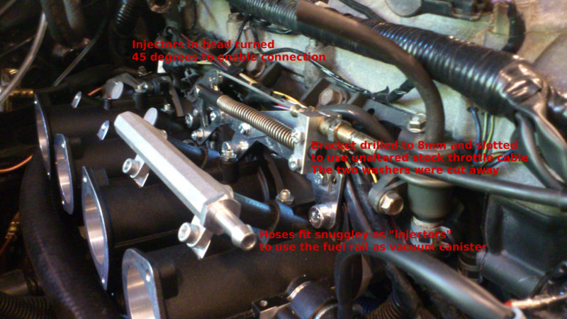
The injectors need to be turned 45 degrees to make the connector fit with the Jenvey intake in place. This also made me ditch the plastic cover for the injector harness.
I had not expected to get any vacuum at all, since turning dummy injectors and use the supplied Jenvey fuel rail for vacuum would be too much work.
Behind my back my fried had started to make dummy injectors out of pieces of hose instead (14mm od fuel hose), it fit tightly and should not leak. And by turning the stock vacuum hose backwards it fit the fire wall end of the Vacuum rail perfectly.
The other end of the rail was connected to the PCV and I'll probably add a T there for FPR and MAP.
The TPS needed connection too and I trashed the AMP connector on the CP17 TPS from Jenvey and guessed a bit regarding SG and 5V.
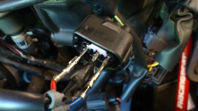
First attempt worked as a charm and this TPS seems to have a wider range than the NB one (sweeps nearer the edge).
I have now just drilled three holes through a plastic square tube, put the three pins through it and filled the tube with hot glue. This connector is then held in place to the NB harness connector with a strap.
This will most probably work well enough for some testing, but does anyone know of a male NB TPS connector anywhere (the Connector Witch Hunt isn't focused on this IIRC)?
What i would like is the male counterpart to http://www.newunitedracetech.com/sho...98_265_268_269
Shifting at 6000 felt too late and I lost massive time in the fast sections.
In the slower sections however, I actually gained on the others, so I now know that the drive-ability of the cams is not terrible.
The tuning could of course be better (bogs at acceleration) but it's better to spend time to get the real stuff in place.
I got some help from one of my friends with much higher productivity in the garage.
Since I still need to get the stock engine in here with the stock ECU for the annual inspection I don't want to throw any stock things away.
* Stock throttle cable setup would be beneficial
* Attaching TPS to the NB TPS connector would be nice
* Stock vacuum would be nice
* Injectors i the head would make it easier to swap in the 4top if I fail
* The ABS would be nice to retain
The ABS bracket was cut down and the pump was placed on the passenger floor.
The cables going to the pump was elongated.
New brake lines to the MCx2 and the fronts, the pipe to the rear was cut/joint by the firewall. Luckily there was an unused hole in the firewall to fill with the five pipes.
The ABS pump connectors was possible to get through the other hole where I already have the MAP line, VVT OCV etc.
Sealing these holes will need some goo
With the ABS out of the way there is more space for an airbox (I will try with a Pipercross one as a first try, if Burton can get it shipped).
But the fuel pipes and the shock tower reinforcements will make it close.
The throttle bracket is a Jenvey one with single spring, supplied with cable etc.
The stock cable fits but the thread is M8 instead of M6. Drilling it out and slotting it for the wire made the stock cable fit without even loosening it from the pedal.
Routing the cable in from of the engine and only attaching it to the front hoist loop made the cable be as smooth as stock and the range was just perfect (three different ratios to choose from). The header is about 3" from the cable but i'll add some heat blanket anyway.
The injectors need to be turned 45 degrees to make the connector fit with the Jenvey intake in place. This also made me ditch the plastic cover for the injector harness.
I had not expected to get any vacuum at all, since turning dummy injectors and use the supplied Jenvey fuel rail for vacuum would be too much work.
Behind my back my fried had started to make dummy injectors out of pieces of hose instead (14mm od fuel hose), it fit tightly and should not leak. And by turning the stock vacuum hose backwards it fit the fire wall end of the Vacuum rail perfectly.
The other end of the rail was connected to the PCV and I'll probably add a T there for FPR and MAP.
The TPS needed connection too and I trashed the AMP connector on the CP17 TPS from Jenvey and guessed a bit regarding SG and 5V.
First attempt worked as a charm and this TPS seems to have a wider range than the NB one (sweeps nearer the edge).
I have now just drilled three holes through a plastic square tube, put the three pins through it and filled the tube with hot glue. This connector is then held in place to the NB harness connector with a strap.
This will most probably work well enough for some testing, but does anyone know of a male NB TPS connector anywhere (the Connector Witch Hunt isn't focused on this IIRC)?
What i would like is the male counterpart to http://www.newunitedracetech.com/sho...98_265_268_269
Last edited by NiklasFalk; 07-23-2013 at 11:48 AM.
Reply
0
0
07-24-2013, 11:05 AM
#11
Senior Member
Thread Starter
iTrader: (1)
Join Date: Jun 2006
Location: Sweden
Posts: 1,391
Total Cats: 63
My airbox in held up in Germany by DHL due to "technical problems" so I just capped the EGR tube on the 01 RB header (M16*1.5 for $0.5) and adjusted the throttle cable a bit.
The idle is so much smoother (at around 1000rpm) without the plenum intake and it now sounds like any other snarly weber equipped I4 (a bit boring since I'm surrounded by them in the pits).
Maybe another visit to a Rototest in the weekend, and hopefully the curve will stretch a bit.
The idle is so much smoother (at around 1000rpm) without the plenum intake and it now sounds like any other snarly weber equipped I4 (a bit boring since I'm surrounded by them in the pits).
Maybe another visit to a Rototest in the weekend, and hopefully the curve will stretch a bit.
Last edited by NiklasFalk; 07-24-2013 at 11:45 AM.
Reply
0
0
07-27-2013, 04:26 PM
#12
Senior Member
Thread Starter
iTrader: (1)
Join Date: Jun 2006
Location: Sweden
Posts: 1,391
Total Cats: 63
Another couple of hours on the Rototest
With no airbox the trumpets were LOUD.
The result was the expexted up high but the dips in the middle were different between sweeps without touching anything...
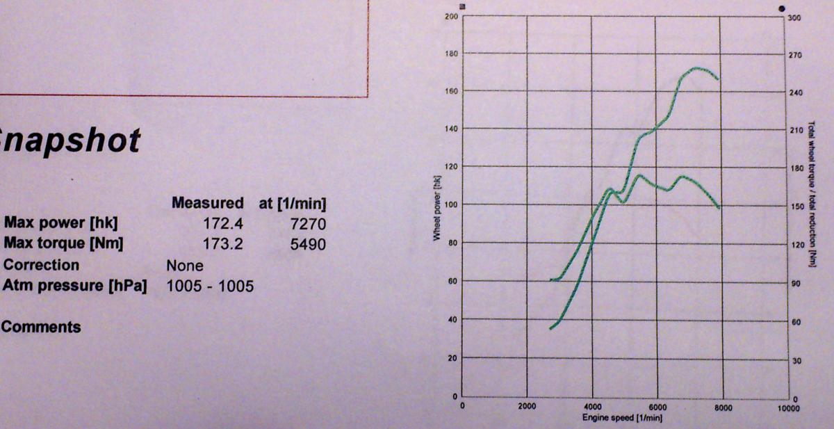
I'm decently happy with the 172 hub hp. There might be 5% more in there with higher compression (and a bit lower spark) but the top did not gain anything now from 2% more or less fuel (it did not change much at all).
Spark ended up at 36 (we did not dare to go higher).
I did one mistake with my feet and the revs maxed at 10.3k, without a boom or even the sound of floating valves. I will not try that again but the springs seems to do their job...
The VVT + VVtuner is a strange combination.
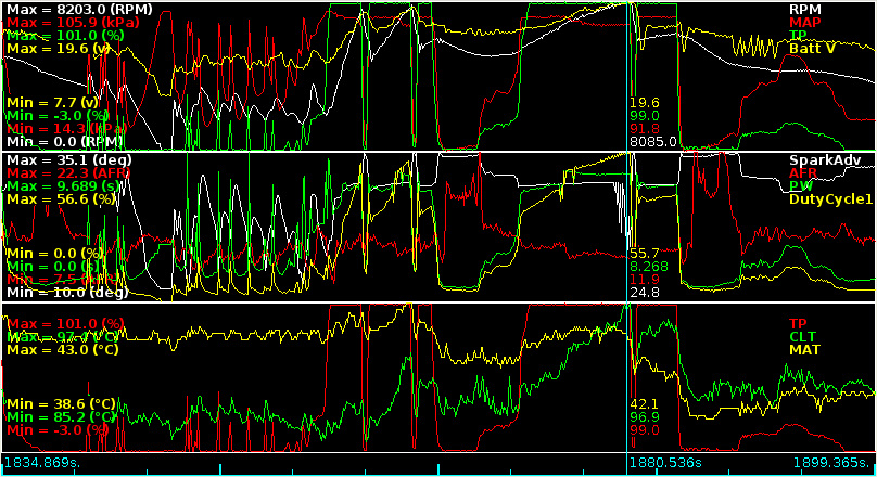
After lunch I did three sweeps concentrating on the diff between target and advance.
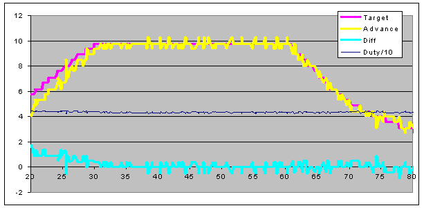
first with a bit colder oil (assumption, no meter)
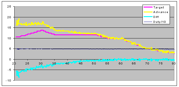
Second where the advance became higher...
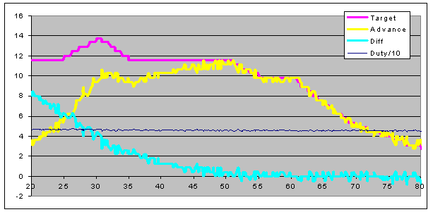
Third showing the most common behavious, not enough oil to get the advance down low but after 4kprm there is no problem reaching the target.
The PID values are 24,12,0 for all three and it has no problem getting to the changed target when there is revs.
The logged Duty Cycle of the OCV must be bougus for some reason, No way it could regulate with the valve constant over the whole rev range (more like 90% at idle and 20% up high).
Thicker and colder oil would help I guess.
Would the VVT control in the MS3 be better (it won't fix the hydraulic fact that my cam is to tough to advance with low rev oil pressure)?
Separate pump for the VVT?
With no airbox the trumpets were LOUD.
The result was the expexted up high but the dips in the middle were different between sweeps without touching anything...
I'm decently happy with the 172 hub hp. There might be 5% more in there with higher compression (and a bit lower spark) but the top did not gain anything now from 2% more or less fuel (it did not change much at all).
Spark ended up at 36 (we did not dare to go higher).
I did one mistake with my feet and the revs maxed at 10.3k, without a boom or even the sound of floating valves. I will not try that again but the springs seems to do their job...
The VVT + VVtuner is a strange combination.
After lunch I did three sweeps concentrating on the diff between target and advance.
first with a bit colder oil (assumption, no meter)
Second where the advance became higher...
Third showing the most common behavious, not enough oil to get the advance down low but after 4kprm there is no problem reaching the target.
The PID values are 24,12,0 for all three and it has no problem getting to the changed target when there is revs.
The logged Duty Cycle of the OCV must be bougus for some reason, No way it could regulate with the valve constant over the whole rev range (more like 90% at idle and 20% up high).
Thicker and colder oil would help I guess.
Would the VVT control in the MS3 be better (it won't fix the hydraulic fact that my cam is to tough to advance with low rev oil pressure)?
Separate pump for the VVT?
Reply
0
0
04-08-2014, 04:07 PM
#15
Senior Member
Thread Starter
iTrader: (1)
Join Date: Jun 2006
Location: Sweden
Posts: 1,391
Total Cats: 63
Soon time for the 2014 season (3-4/5).
Last season ended with a broken clutch (unable to disengage). Replacing the cylinders did not help.
When I finally pulled the engine (six months later) is was pretty clear what the problem was
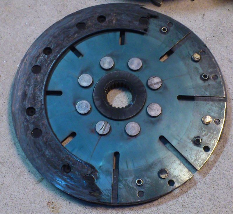
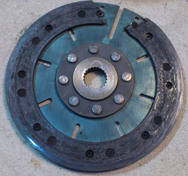
Emilio advised me to just replace the disk and try again. If the next carbon disc doesn't hold up I'll go ceramic instead.
The lost material was found as dust in the pressure plate preventing it to move I assume, the exact logic does not matter. No marks in the flywheel or pressure plate from the rivets at least.
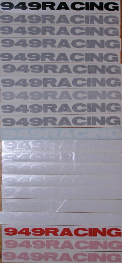
When I got the shipment today I just could not resist to take a picture of the 949 decal collection (more than one per purchase, thankfully)
Besides all the other small things (like rebuilding to street legal, getting it inspected and then put things back), I plan (it would be nice) to advance with the exhaust cam (4 or 6 degrees) before the end of April...
Last season ended with a broken clutch (unable to disengage). Replacing the cylinders did not help.
When I finally pulled the engine (six months later) is was pretty clear what the problem was
Emilio advised me to just replace the disk and try again. If the next carbon disc doesn't hold up I'll go ceramic instead.
The lost material was found as dust in the pressure plate preventing it to move I assume, the exact logic does not matter. No marks in the flywheel or pressure plate from the rivets at least.
When I got the shipment today I just could not resist to take a picture of the 949 decal collection (more than one per purchase, thankfully)
Besides all the other small things (like rebuilding to street legal, getting it inspected and then put things back), I plan (it would be nice) to advance with the exhaust cam (4 or 6 degrees) before the end of April...
Reply
0
0
08-23-2014, 10:13 AM
#16
Senior Member
Thread Starter
iTrader: (1)
Join Date: Jun 2006
Location: Sweden
Posts: 1,391
Total Cats: 63
The season is almost over with just one race left.
During this season i have played a little with exhaust cam timing without going to a dyno.
Going from 105 I changed to 107 and the thing started to come alive and that race weekend was fun and made a few surprised that I actually could keep up.
For the next race I tested 110 and that was not a success, but not as bad as 105.
For the last weekend I went back to 108 and that seems to be a decent setting.
But at the same time I adjusted a few bits so a direct comparison might not work.
But it would help to get a decent pull from below 5000, now I need to be at 5200 or higher out of the corner to get a decent response. A six speed is on the wish list.
Besides the small repair work (tie rod, lower hub bolt and some sheet metal) I got two new cam blanks from Bill Wilner.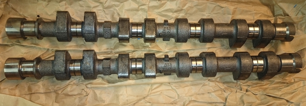
One of them will be ground to a 298 exhaust cam
Someone asked for engine bay pics to see the current Jenvey setup.
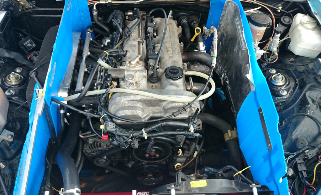
The dummy injectors made from hoses still work and I now have a reasonably steady idle of 1200rpm (just 3/4 tun on each bleed screw, no proper balancing).
I know it could be cleaned up a lot, but it works well enough for me.
When I get a new exh cam ground and get to the Rototest for proper tuning it will be spring next year. I really hope it will wake up at 4800 or so, and if I stumble over a six speed it would not hurt (even if my 4.875 will make me shift to 6th more often than ideal).
During this season i have played a little with exhaust cam timing without going to a dyno.
Going from 105 I changed to 107 and the thing started to come alive and that race weekend was fun and made a few surprised that I actually could keep up.
For the next race I tested 110 and that was not a success, but not as bad as 105.
For the last weekend I went back to 108 and that seems to be a decent setting.
But at the same time I adjusted a few bits so a direct comparison might not work.
But it would help to get a decent pull from below 5000, now I need to be at 5200 or higher out of the corner to get a decent response. A six speed is on the wish list.
Besides the small repair work (tie rod, lower hub bolt and some sheet metal) I got two new cam blanks from Bill Wilner.
One of them will be ground to a 298 exhaust cam
Someone asked for engine bay pics to see the current Jenvey setup.
The dummy injectors made from hoses still work and I now have a reasonably steady idle of 1200rpm (just 3/4 tun on each bleed screw, no proper balancing).
I know it could be cleaned up a lot, but it works well enough for me.
When I get a new exh cam ground and get to the Rototest for proper tuning it will be spring next year. I really hope it will wake up at 4800 or so, and if I stumble over a six speed it would not hurt (even if my 4.875 will make me shift to 6th more often than ideal).
Reply
0
0
 08-23-2014, 02:13 PM
#18
Senior Member
Thread Starter
iTrader: (1)
Join Date: Jun 2006
Location: Sweden
Posts: 1,391
Total Cats: 63
It's inspired by a heats shield seen on one incarnation of https://www.miataturbo.net/race-prep...6/#post1049680, the exhaust side was made just because it was easy (one straight alu squre tube). I was worried that the PP plastic would melt but it have held up nicely, but it have not been hotter than 80F ambient with it mounted.
One thing I have noticed it that it seems to blow air from the sides into the center (I have no inner fenders at all, just gaping holes), meaning that the air pressure in the wheel wells are higher.
So to improve cooling when it's really hot, keeping the inner fenders or blocking that path in some other way might be beneficial.
Venting the wheel wells at the top of the fenders might help too.
Last edited by NiklasFalk; 08-23-2014 at 02:29 PM.
Reply
0
0

Thread
Thread Starter
Forum
Replies
Last Post
StratoBlue1109
Miata parts for sale/trade
21
09-30-2018 01:09 PM


