NOT A MIATA, FE3N+HOLSET+73 FORD COURIER BUILD
 08-17-2016, 08:48 PM
#1
Senior Member
Thread Starter

Join Date: Jan 2011
Location: sacramento ,ca
Posts: 563
Total Cats: 160
my buddy said that you all would like to see my fast piece of **** im building. heres a copy and paste of my build thread from ----------------------
so i picked up this ford courier a few moths back with the dream of decent handling, solid braking, and 500whp.
what im going to be using:
Engine:
Kia/mazda FE3N possibly gasket matched ports but thats about it
Induction:
Holeset HX35 with BEP T3 housing
Tial MVS 38mm external waste gate
Drive train:
Mazda B2600 trans- possibly with the RX7 TII gears inside
99 Ford Explorer 8.8 3.73 lsd 31 spline with disc brakes
custom drive shaft
i havent decided on what clutch im going to run yet, i loved my spec so i might go that route
Suspension:
Rear:
triangulated 4 link with coil overs mounted as far out as possible
Front:
full mustang 2 front end narrowed 5"
Brakes:
front Ford Granada 11" rotors with metric GM calipers and pads(standard Mustang II "big brake" set up)
stock ford explorer rear discs, calipers, and e brake
there is a lot i have to get into place before i can even get the engine/trans mounted
first i had to weld in some temporary cross members to keep the frame straight. then i got to remove the stock garbage. 6 hrs, one plasma cutter tip, 4 cut off wheels, and 2 full grinding wheels later the frame rails were all pretty
http://i271.photobucket.com/albums/jj146/aintnobitch/courier/stock%20front%20end.jpg
http://i271.photobucket.com/albums/jj146/aintnobitch/courier/stock%20front%20end%20removed.jpg
using this awesome thread How to Mustang II, Deux! The H.A.M.B. i was able to figure out i needed my cross member to be narrowed 5" to set the proper track width.
i drew up my measurements on a piece of 10ga plate and got cutting
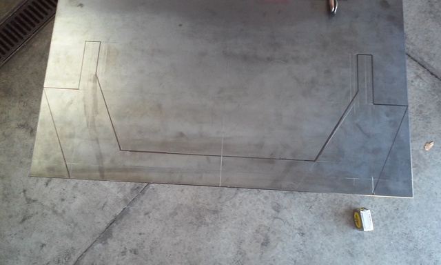
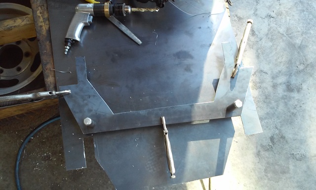
i bolted the 2 plates together, leveled my frame,centered them on my lines, leveled the cross member, and weled them up
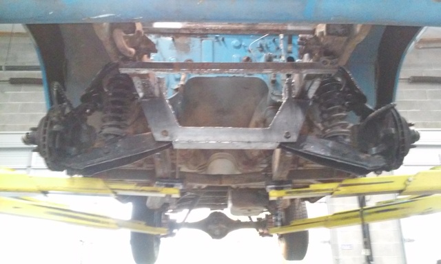
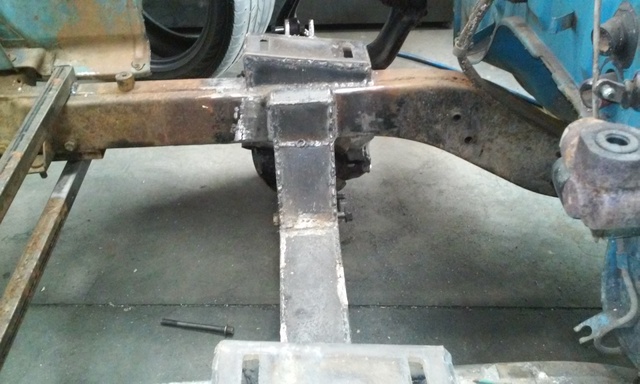
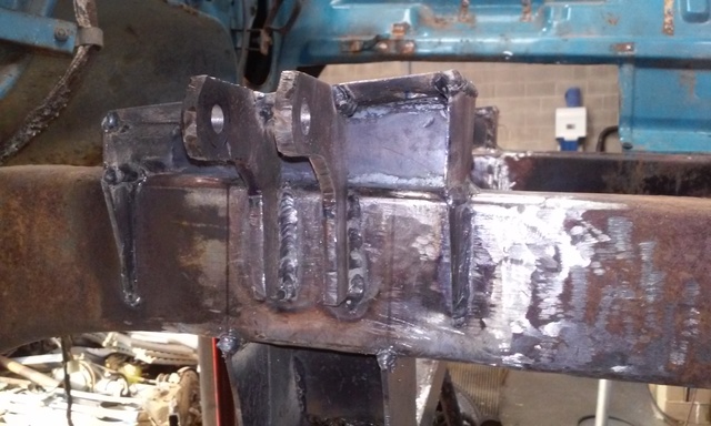
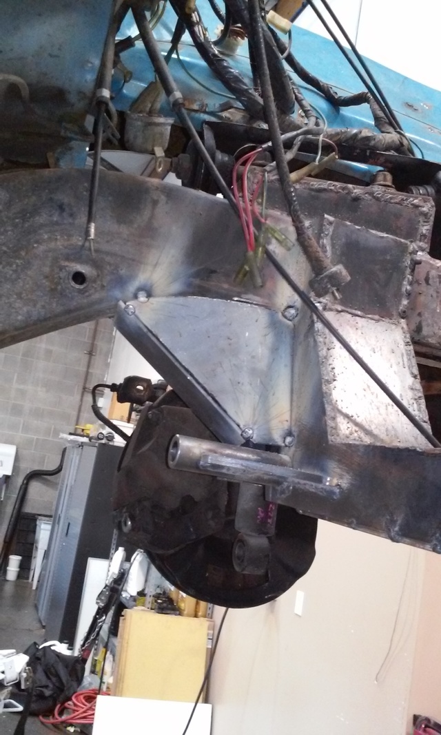
I made the upper control arm mounts out of 1/4 plate. i used the mustang 2 anti-dive angle instead of making them flat because its a truck and it will be front end heavy.
i centered and bolted the uca mounts to a pair of extra bars i had laying around to make sure they didnt move. i then double checked that the frame was level and centered the uca mounts with a plumb bob. once they were welded into place i boxed them in with 10ga plate and gusseted the over hang and welded in the shock mounts which are also made from 1/4 plate.
so i picked up this ford courier a few moths back with the dream of decent handling, solid braking, and 500whp.
what im going to be using:
Engine:
Kia/mazda FE3N possibly gasket matched ports but thats about it
Induction:
Holeset HX35 with BEP T3 housing
Tial MVS 38mm external waste gate
Drive train:
Mazda B2600 trans- possibly with the RX7 TII gears inside
99 Ford Explorer 8.8 3.73 lsd 31 spline with disc brakes
custom drive shaft
i havent decided on what clutch im going to run yet, i loved my spec so i might go that route
Suspension:
Rear:
triangulated 4 link with coil overs mounted as far out as possible
Front:
full mustang 2 front end narrowed 5"
Brakes:
front Ford Granada 11" rotors with metric GM calipers and pads(standard Mustang II "big brake" set up)
stock ford explorer rear discs, calipers, and e brake
there is a lot i have to get into place before i can even get the engine/trans mounted
first i had to weld in some temporary cross members to keep the frame straight. then i got to remove the stock garbage. 6 hrs, one plasma cutter tip, 4 cut off wheels, and 2 full grinding wheels later the frame rails were all pretty
http://i271.photobucket.com/albums/jj146/aintnobitch/courier/stock%20front%20end.jpg
http://i271.photobucket.com/albums/jj146/aintnobitch/courier/stock%20front%20end%20removed.jpg
using this awesome thread How to Mustang II, Deux! The H.A.M.B. i was able to figure out i needed my cross member to be narrowed 5" to set the proper track width.
i drew up my measurements on a piece of 10ga plate and got cutting
i bolted the 2 plates together, leveled my frame,centered them on my lines, leveled the cross member, and weled them up
I made the upper control arm mounts out of 1/4 plate. i used the mustang 2 anti-dive angle instead of making them flat because its a truck and it will be front end heavy.
i centered and bolted the uca mounts to a pair of extra bars i had laying around to make sure they didnt move. i then double checked that the frame was level and centered the uca mounts with a plumb bob. once they were welded into place i boxed them in with 10ga plate and gusseted the over hang and welded in the shock mounts which are also made from 1/4 plate.
Last edited by fastivab6tg25mr; 01-28-2018 at 12:43 PM. Reason: Broken thread

Reply
 3
3

3
08-17-2016, 08:50 PM
#2
Senior Member
Thread Starter
Join Date: Jan 2011
Location: sacramento ,ca
Posts: 563
Total Cats: 160
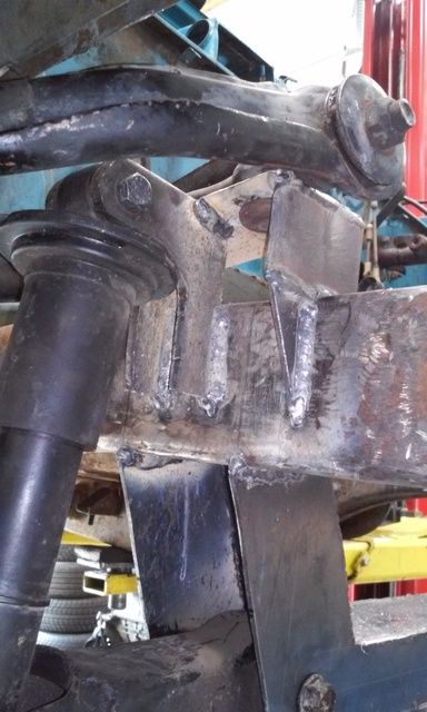
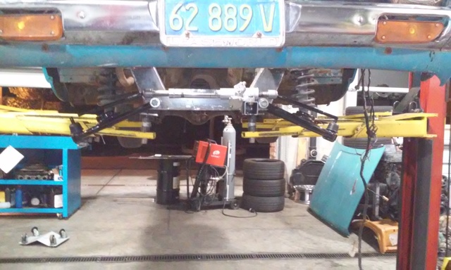
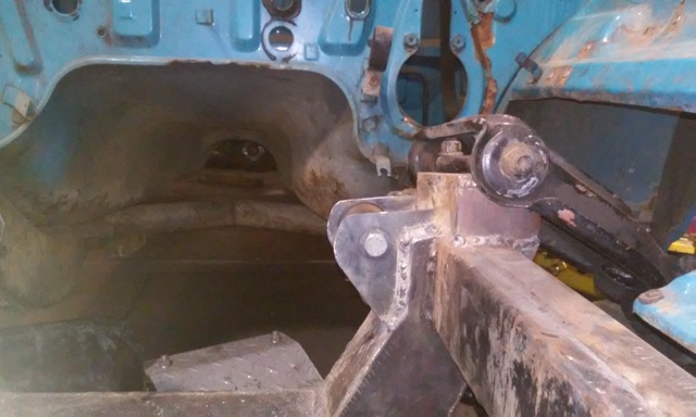
slow at work so me and my boss started playing around with ideal ride height. put the tires(245-40-17) in the wheel wells and set it on stands but then we got busy so i spent the rest of the day staring at it. the more i stared the more i wanted to drive it. with that motivation i finished my tubular control arms mounts, welded in cross member reinforcements and got my main steering rack mount in. tonight i pulled the cab off to fit the engine. looks like the fire wall will need to pushed back round 8 inches to get the engine seated low enough and back enough to make me happy. more pics to come


Last edited by fastivab6tg25mr; 08-17-2016 at 09:00 PM.
Reply
0
0
08-17-2016, 08:51 PM
#3
Senior Member
Thread Starter
Join Date: Jan 2011
Location: sacramento ,ca
Posts: 563
Total Cats: 160
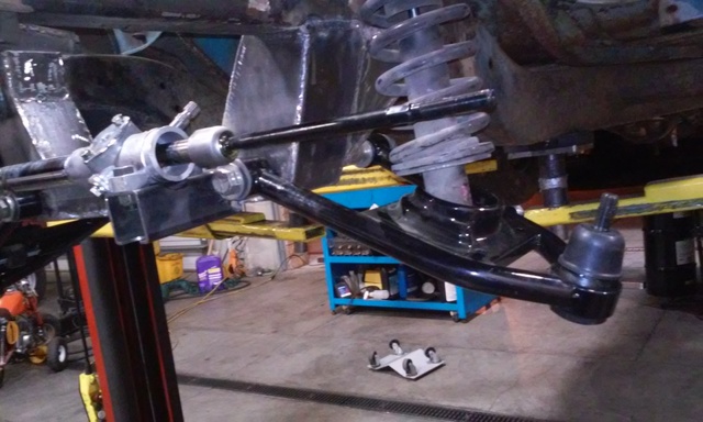
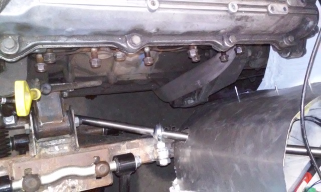
after a week of going back and forth with amazon trying to get my Chassis Engineering rack mount kit and continuously getting the wrong part i said **** it im making my own.
a piece of 1/2" wide by 2" tall aluminum
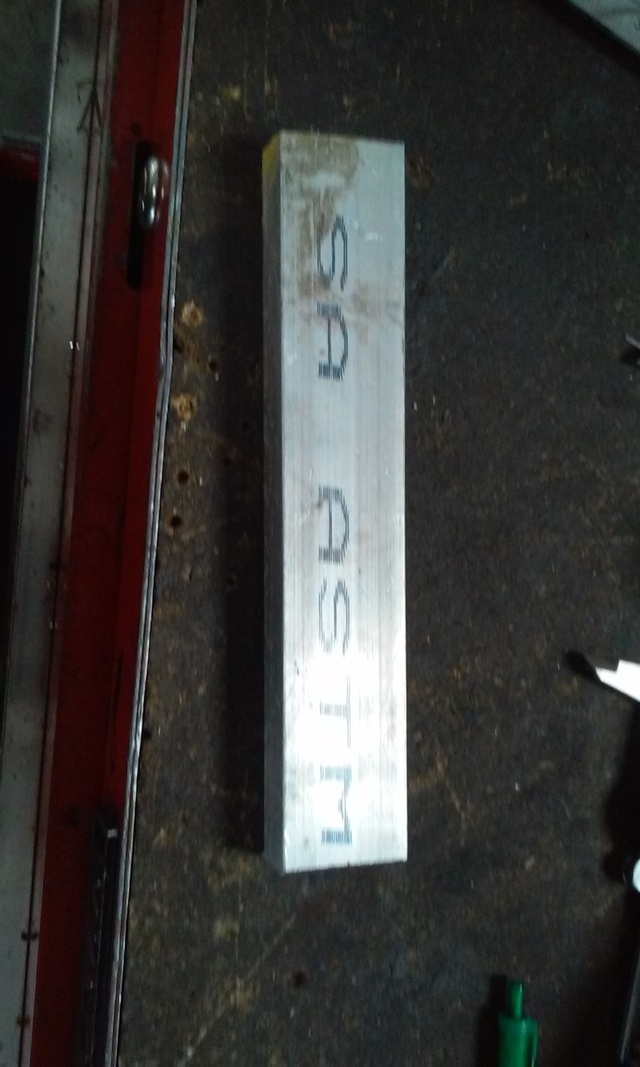
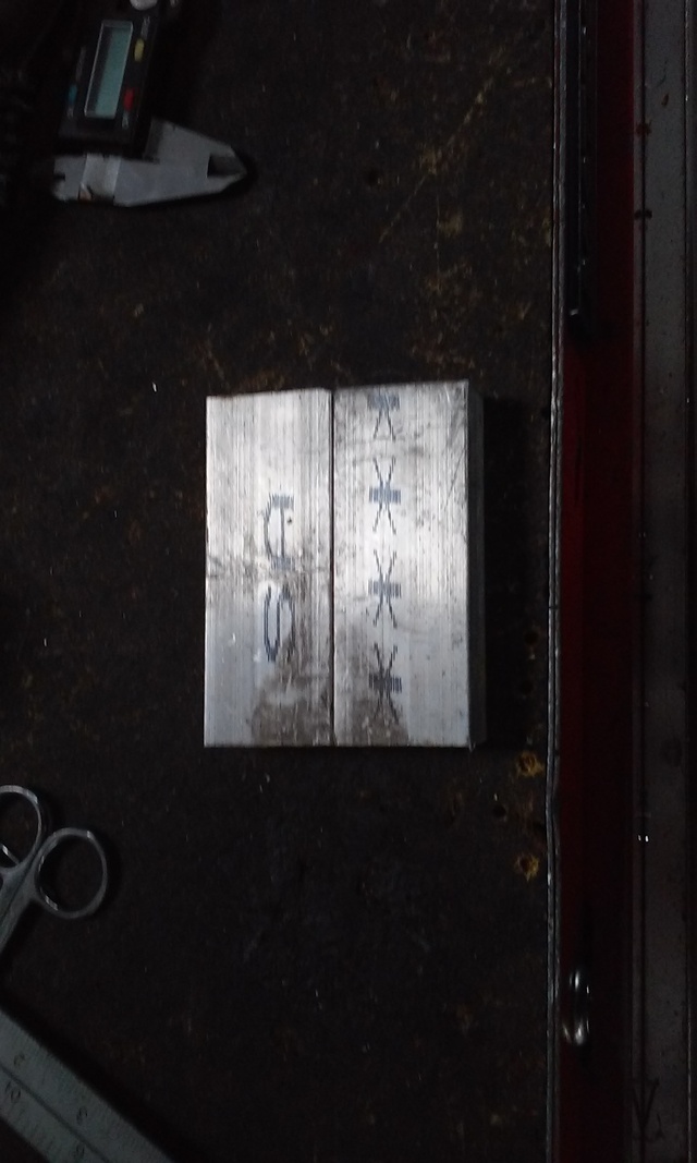
making threaded inserts
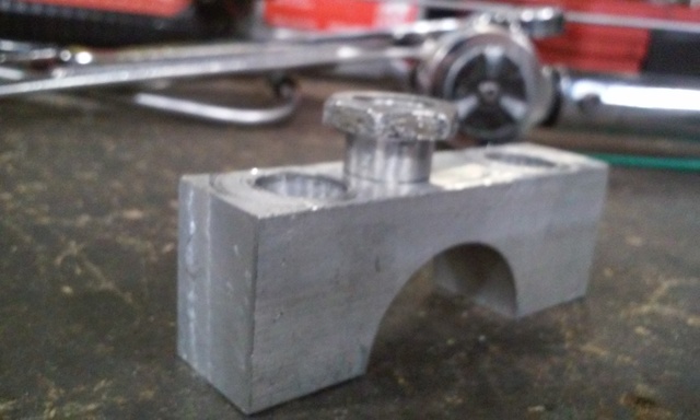
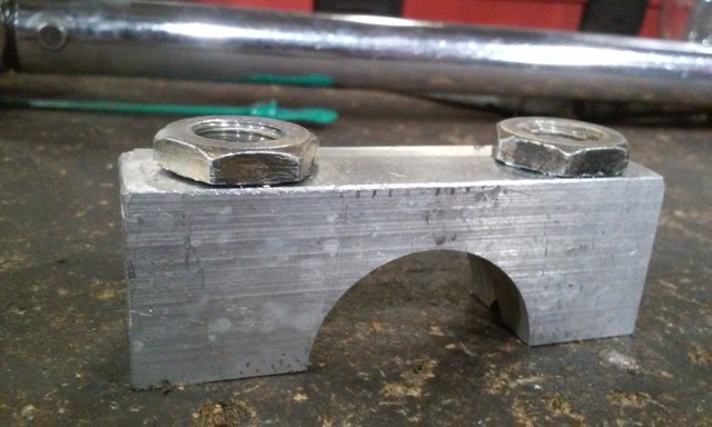
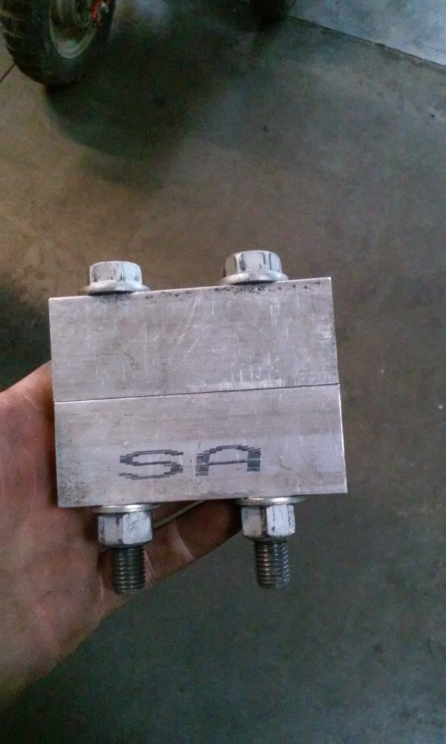
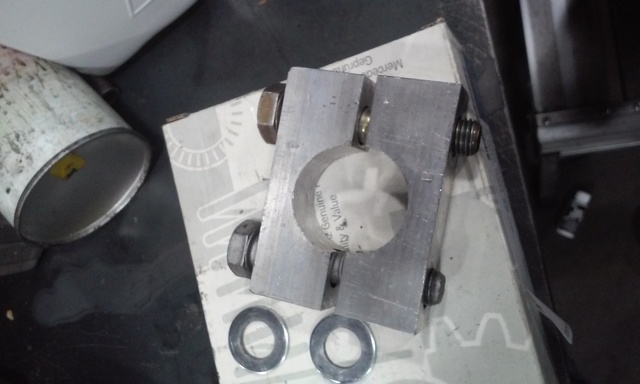
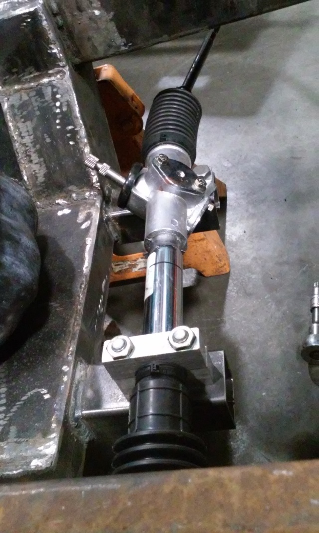
finally mounted. i could probably lift the car from this rack lol
a piece of 1/2" wide by 2" tall aluminum
making threaded inserts
finally mounted. i could probably lift the car from this rack lol
Last edited by fastivab6tg25mr; 08-17-2016 at 09:04 PM.
Reply
1
1
 08-17-2016, 09:06 PM
#6
Senior Member
Thread Starter
Join Date: Jan 2011
Location: sacramento ,ca
Posts: 563
Total Cats: 160
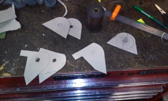
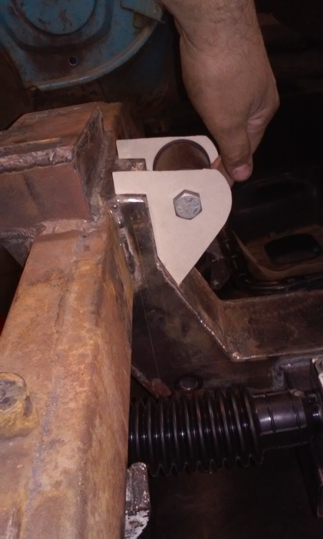
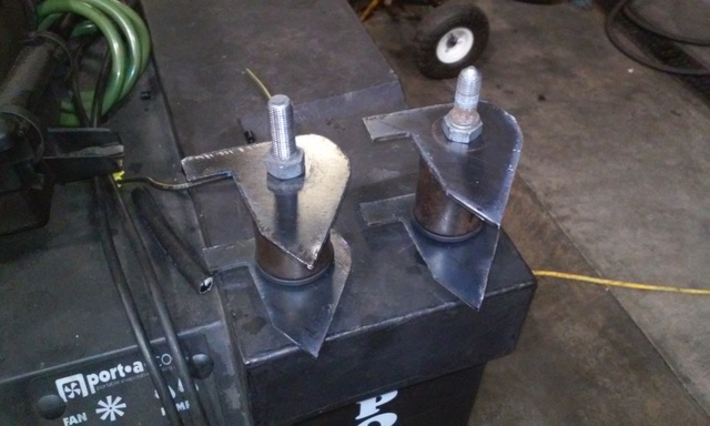
playing with some card board i came up with my engine mount brackets. took a few tries but i think i have the design down.Gonna make them out of the same 10ga the cross member is made of... when all boxed up it should be plenty strong enough to hold my projected 500whp in place.
P.S. when im done im gonna turn this thread into a photo album that stays in my truck to beat the **** out of all the **** cambered out with rims with "built not bought" stickers
P.S. when im done im gonna turn this thread into a photo album that stays in my truck to beat the **** out of all the **** cambered out with rims with "built not bought" stickers
Reply
0
0
08-17-2016, 09:08 PM
#7
Senior Member
Thread Starter
Join Date: Jan 2011
Location: sacramento ,ca
Posts: 563
Total Cats: 160
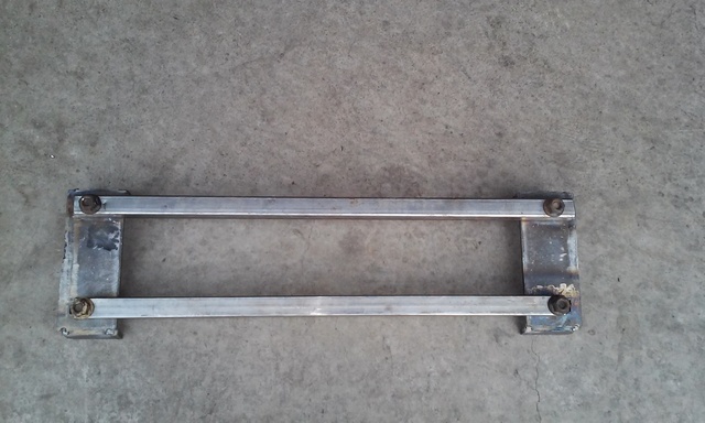
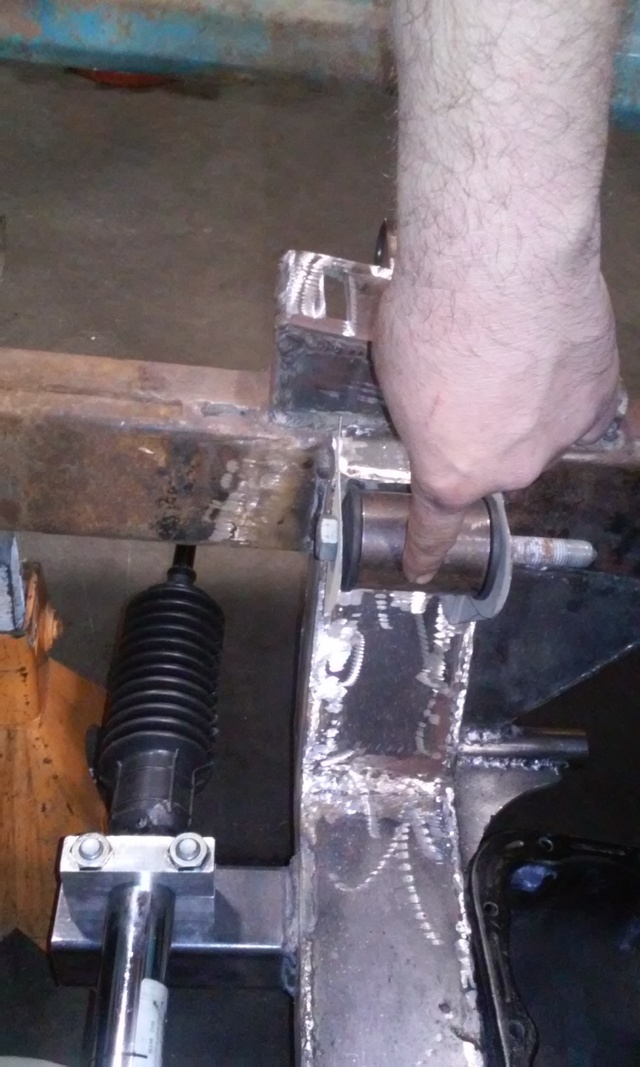
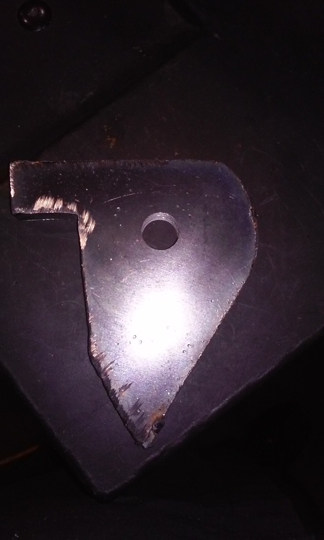
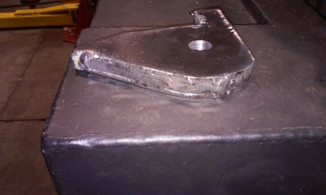
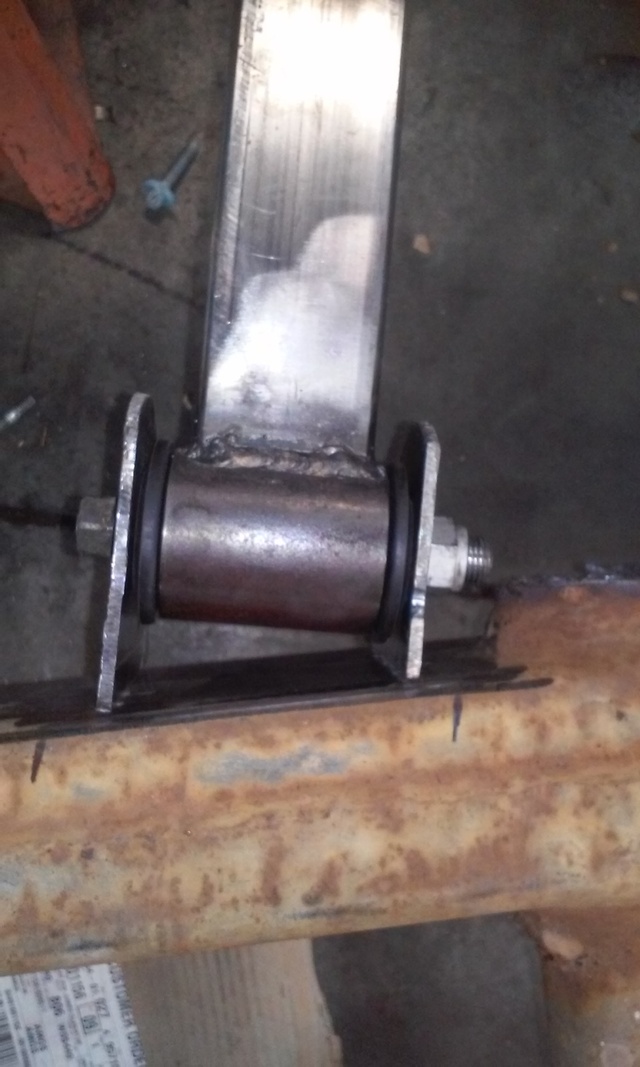
i transferred my cardboard design to some 10ga.Cut them out with a plasma cutter then welded all 4 together so i could grind them into shape and drill the holes. bolted them to the mounts to get the proper spacing. removed the center collar from the bushing and bolted it in by itself before welding it up. i might have the motor in this weekend.
Reply
0
0
 08-17-2016, 09:09 PM
#9
Senior Member
Thread Starter
Join Date: Jan 2011
Location: sacramento ,ca
Posts: 563
Total Cats: 160
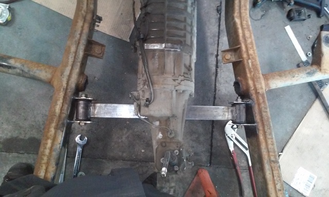
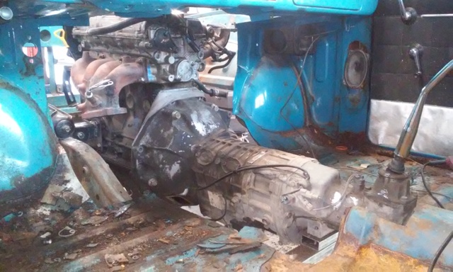
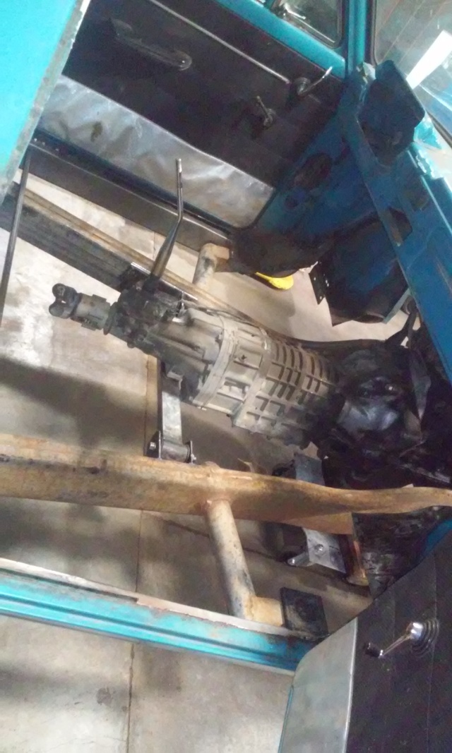
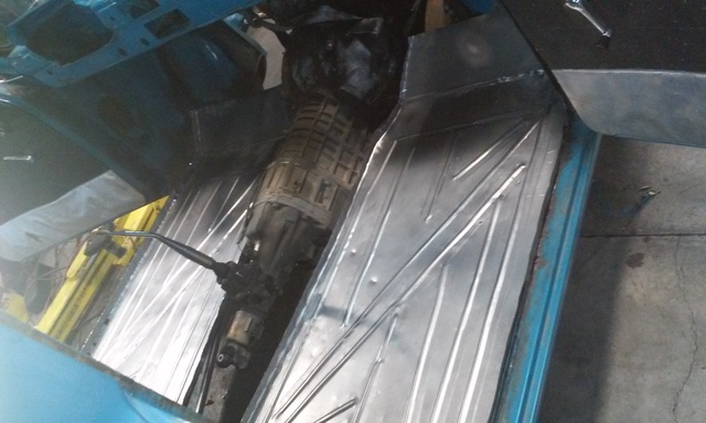
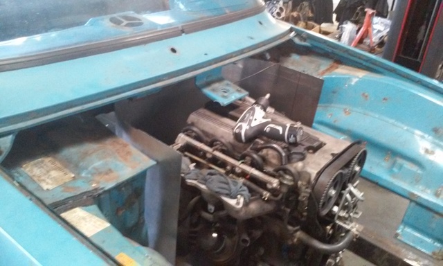
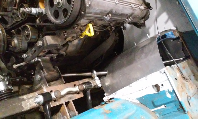
i took the week off of work for a vacation but ended up not going. just more time to work on my truck. finished the trans cross member/mounts. used the same poly bushings that i used for the engine mounts on a piece pf 1x2. with the engine and trans set where i wanted them i started cutting until the cab fit. over the engine/trans. this FE3N is a little bigger than i first thought it was.
Reply
0
0
08-17-2016, 09:11 PM
#10
Senior Member
Thread Starter
Join Date: Jan 2011
Location: sacramento ,ca
Posts: 563
Total Cats: 160
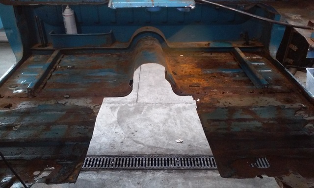
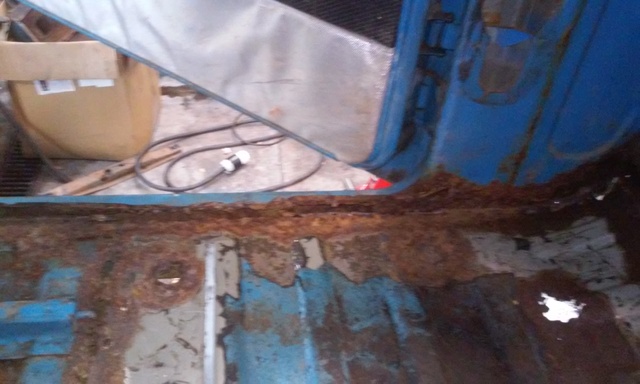
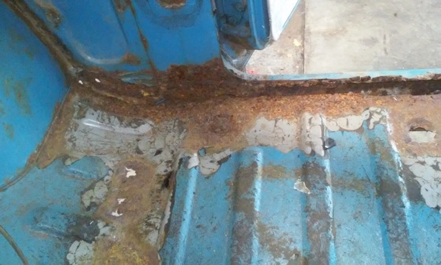
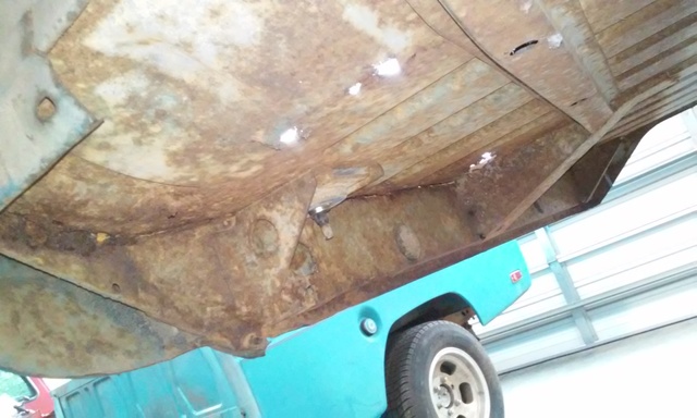
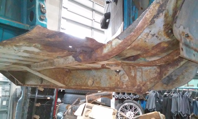
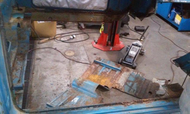
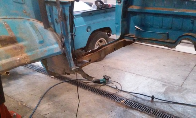
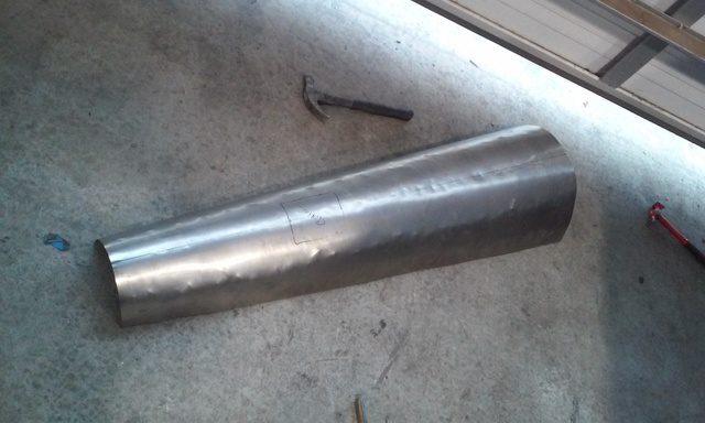
pulled the cab back off to fix some rust before making the new tunnel. turns out there is a **** ton more rust than i originally thought so now i have to fix all of that before i can even think of making a floor. im a very shitty body guy so any tips will be appreciated. im just taking what i think is the logical approach and cutting everything out until there is good solid metal, tracing a pattern onto some 20ga, cut, drill, plug weld.
Reply
0
0
08-17-2016, 09:12 PM
#11
Senior Member
Thread Starter
Join Date: Jan 2011
Location: sacramento ,ca
Posts: 563
Total Cats: 160
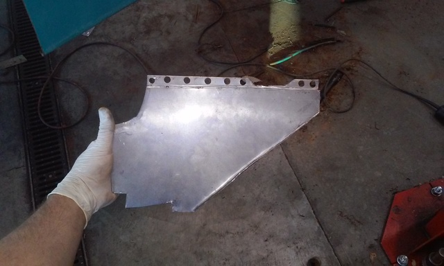
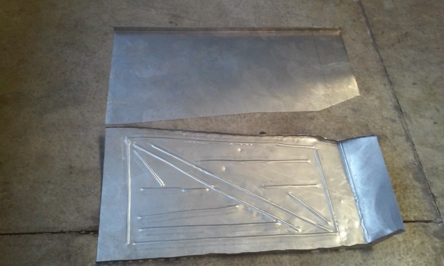
got the cab mounted back to the frame and started working on my floor boards with my shitty harbor freight bead roller. didnt turn out too bad considering the tools and that this is the first floor ive ever made.
before and after bead rolling
before and after bead rolling
Reply
0
0
08-17-2016, 09:13 PM
#12
Slowest Progress Ever

iTrader: (26)
Join Date: Oct 2007
Location: The coal ridden hills of Pennsylvania
Posts: 6,022
Total Cats: 304
Ford courier...I used to drive one when I was like 14 around a campground picking up trash. Always wondered how cool it would be to bitch one out. Nice selection!
Reply
0
0
08-17-2016, 09:13 PM
#13
Senior Member
Thread Starter
Join Date: Jan 2011
Location: sacramento ,ca
Posts: 563
Total Cats: 160
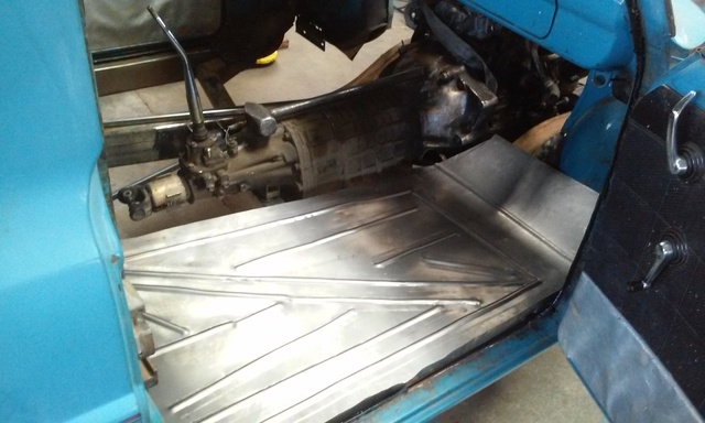
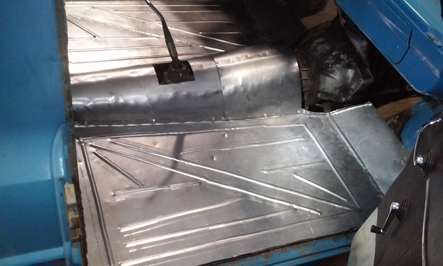
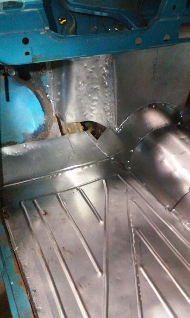
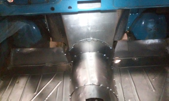
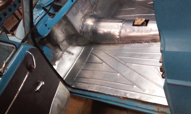
started putting my floor in today. using self tappers to tack it all in place while i form the tranny tunnel. as soon as it all fits to my liking i will seam weld the whole floor in place.
Reply
2
2
08-17-2016, 09:15 PM
#14
Senior Member
Thread Starter
Join Date: Jan 2011
Location: sacramento ,ca
Posts: 563
Total Cats: 160
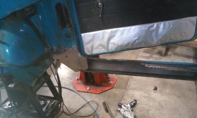
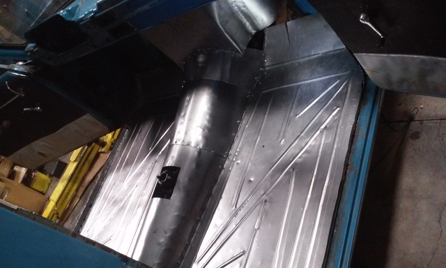
this floor is taking forever and i havent even started welding on it yet.
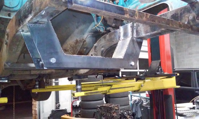
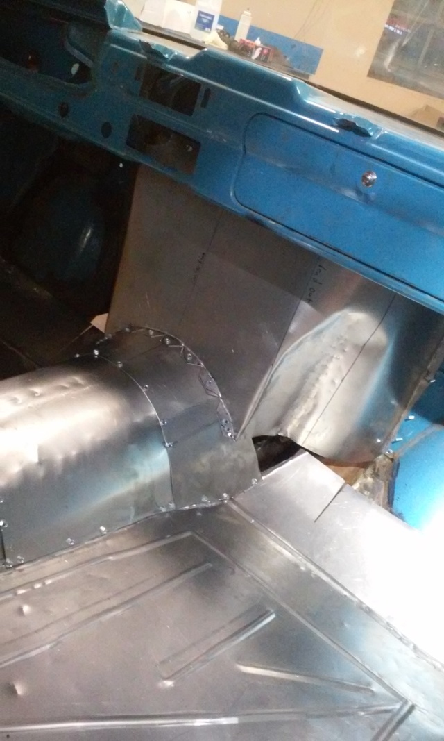
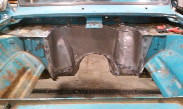
i hand formed the rough shape of the fire wall and screwed it into place. the self tapping screws are very helpful cause i was able make all the marks for bending and cutting, remove it from the cab, make all the bends and cuts and put it back in the exact location so everything lines up.
it was a long day so i didnt get pics of all the shaping and bending of the flanges to join the new fire wall to the cab.
after it was all screwed into place i took my harbor freight body hammers and beat the **** out of the lower sides where i dont need a lot of engine bay space to gain a little foot room. after its all welded im gonna pull the cam and have q buddy hold a dolly on one side so i can smooth out some of the hammer marks.
Reply
0
0
08-17-2016, 09:17 PM
#15
Senior Member
Thread Starter
Join Date: Jan 2011
Location: sacramento ,ca
Posts: 563
Total Cats: 160
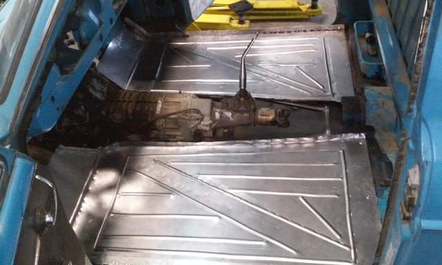
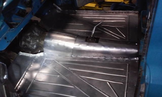
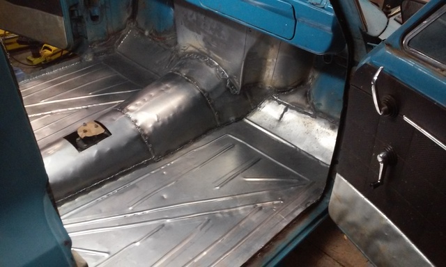
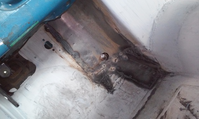
6 hours of welding later i have just about all of the top of my floor welded. it doesnt look like any of it warped. i pulled the cab off to get to the bottom seams right before i left for the day. should be able to finish welding it tomorrow and maybe even put primer on it.
Reply
0
0
08-17-2016, 09:19 PM
#16
Senior Member
Thread Starter
Join Date: Jan 2011
Location: sacramento ,ca
Posts: 563
Total Cats: 160
i was expecting to have to do some bracing but its incredibly solid as it sits with barely any flex even with my fat *** crawling around on it. when i put the seat rails in i will be adding some overkill bracing top and bottom. thats just to make sure the seat stays put if i ever do hit anything.
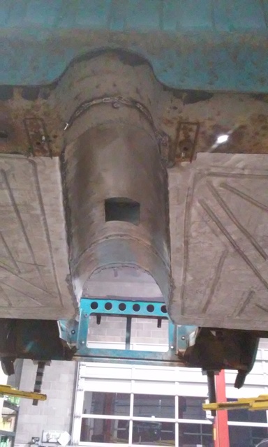
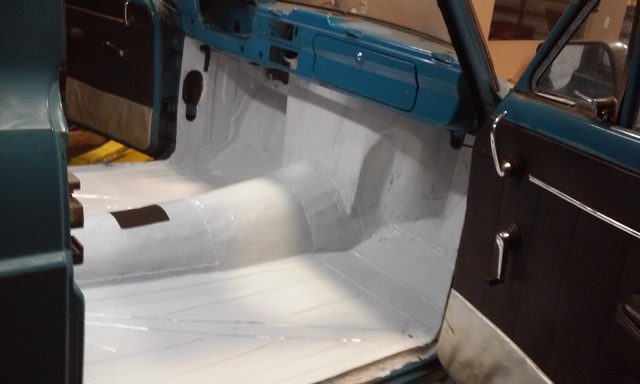
finished the floor and got it seam sealed and primered. there are two spots on the upper fire wall that i missed and will be finishing them today. i just needed t get the primer on it before today so i dont have to worry abut it rusting while it sits outside
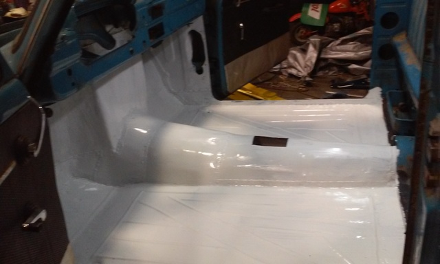
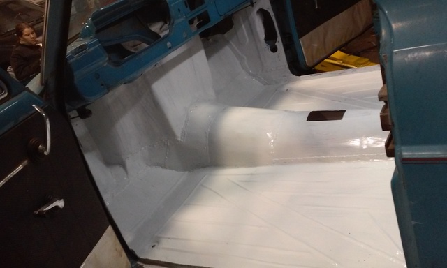
finished the floor and got it seam sealed and primered. there are two spots on the upper fire wall that i missed and will be finishing them today. i just needed t get the primer on it before today so i dont have to worry abut it rusting while it sits outside
Reply
0
0
08-17-2016, 09:21 PM
#17
Senior Member
Thread Starter
Join Date: Jan 2011
Location: sacramento ,ca
Posts: 563
Total Cats: 160
more progress. i picket up upper control arms, steering stuff, 2003 Saab 93 seats, and a short side axle to narrow my 8.8 rear end.
the seats take up a little more room than i originally thought but they are heated, power leather seats and say "Turbo" in the middle so ill work around that. i pulled the seat cover off and cut out the "hump" on the back of the back rest for more clearance. that wasnt enough so i also trimmed the rear cab brace to get an extra few inches. after the seat was installed i realized how little room i had left for my pedals so i had to cut the fire wall out and extend it back into the engine bay.
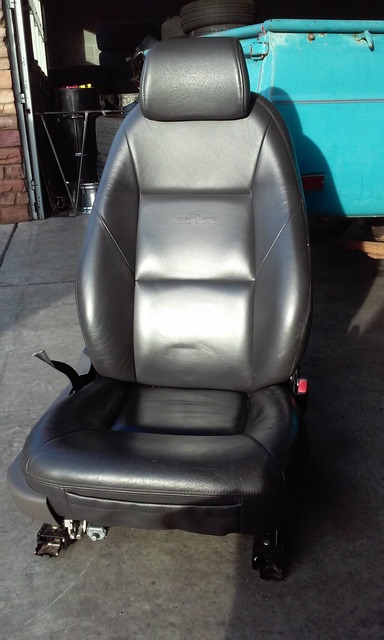
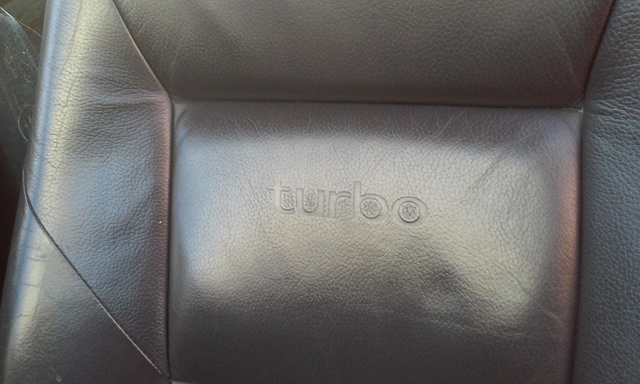
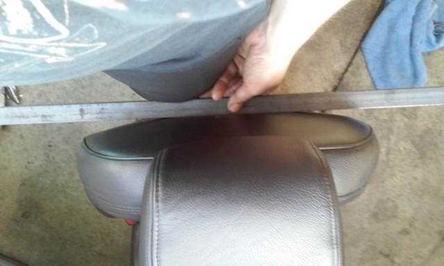
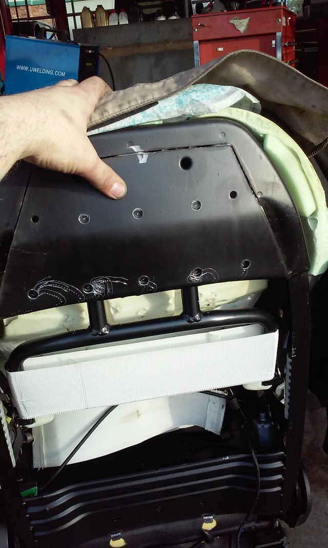
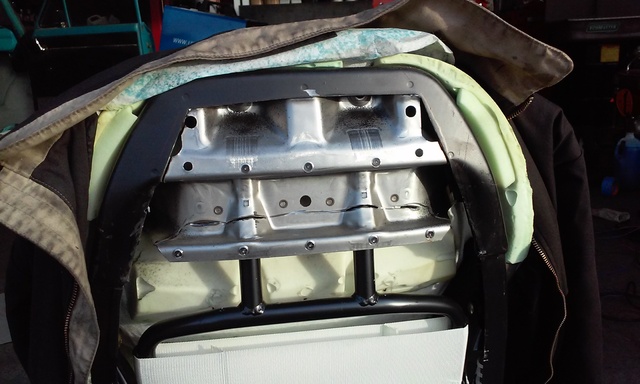
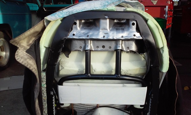
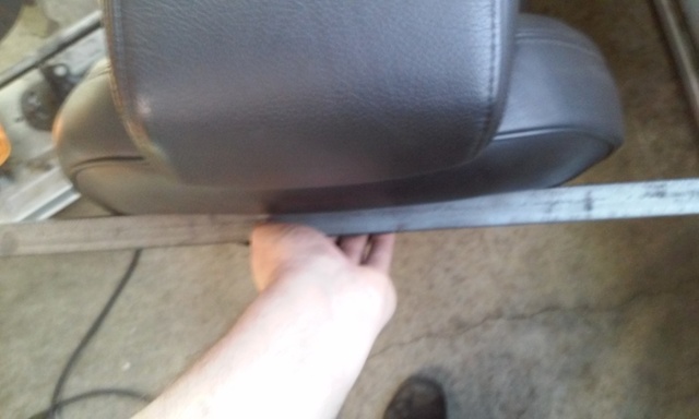
the seats take up a little more room than i originally thought but they are heated, power leather seats and say "Turbo" in the middle so ill work around that. i pulled the seat cover off and cut out the "hump" on the back of the back rest for more clearance. that wasnt enough so i also trimmed the rear cab brace to get an extra few inches. after the seat was installed i realized how little room i had left for my pedals so i had to cut the fire wall out and extend it back into the engine bay.
Reply
0
0
08-17-2016, 09:22 PM
#18
Senior Member
Thread Starter
Join Date: Jan 2011
Location: sacramento ,ca
Posts: 563
Total Cats: 160
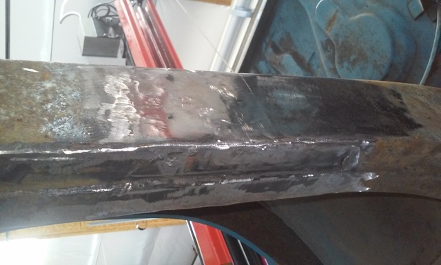
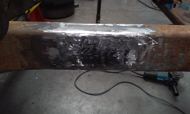
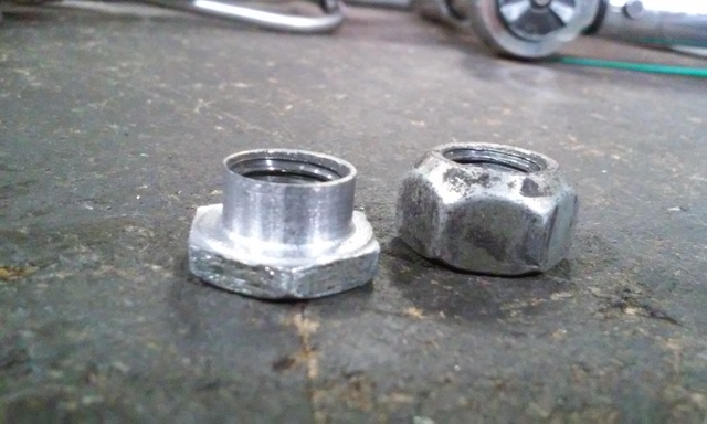
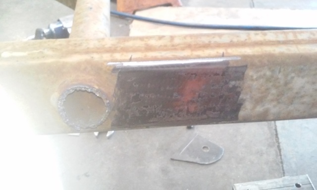
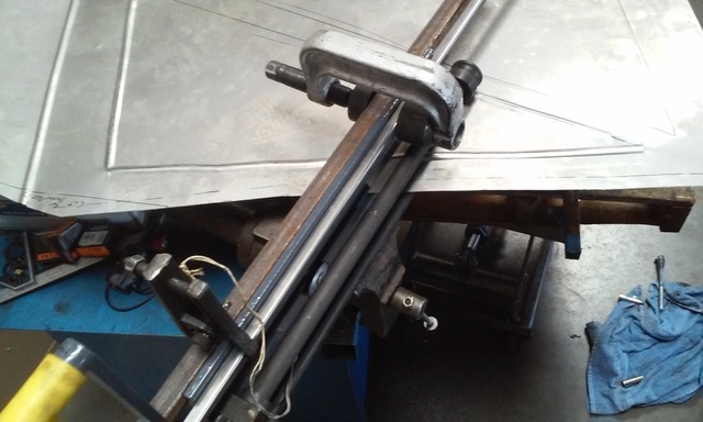
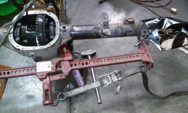
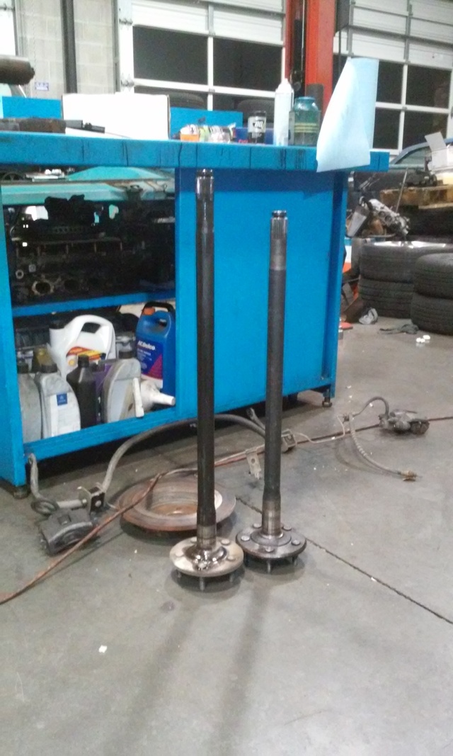
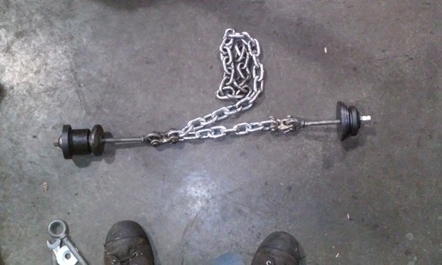
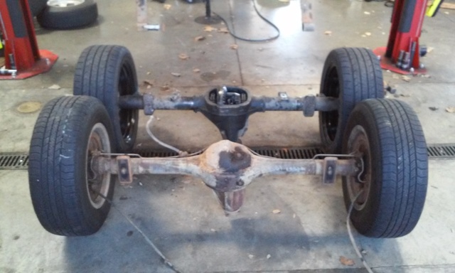
spent most of the day working on narrowing my 8.8. i chose the hard way and drilled the plug welds and hammered out the axle tube then reinstalled it lining up all my marks. it was a huge pain in the *** and if i were to do another i would just cut and weld the tube. installing it was even worse than removing it. i used 2 2200lb eye bolts and shackles hooked to a 2600lb chain through the pumpkin with some bearing press dies threaded around the eye bolts. i had to tighten the bolt as hard as i could then beat the **** out of it while its under tension with a hammer then repeat steps 1 & 2 for eternity each time only moving the tube a millimeter or two. giant pain in the *** but its done and im over it.
drain
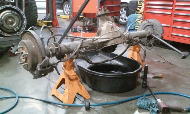
mark
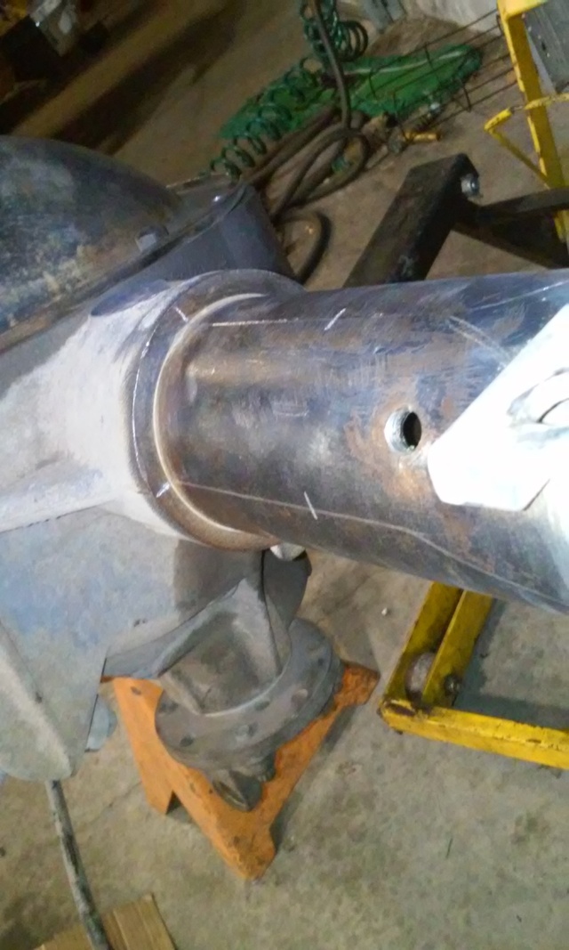
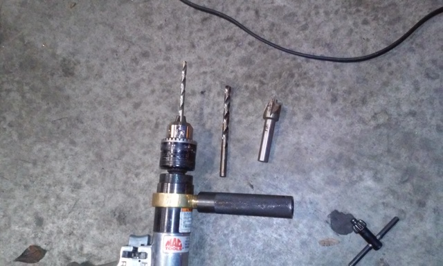
drill- 1/4, 5/16, 18.5mm mill bit
remove all fancy like
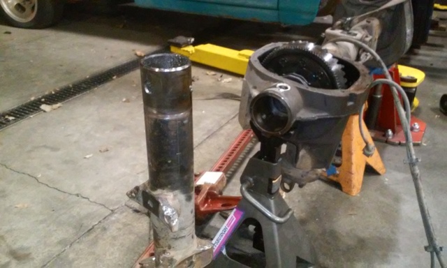
difference in left vs right axle 2 7/8"
fancy press tool
drain
mark
drill- 1/4, 5/16, 18.5mm mill bit
remove all fancy like
difference in left vs right axle 2 7/8"
fancy press tool
Reply
1
1
08-17-2016, 09:25 PM
#19
Senior Member
Thread Starter
Join Date: Jan 2011
Location: sacramento ,ca
Posts: 563
Total Cats: 160
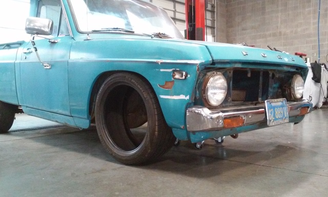
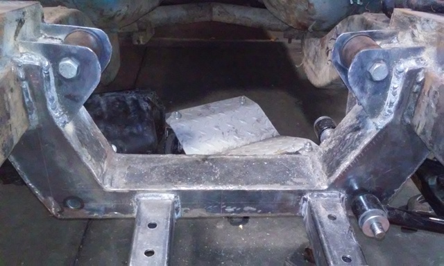
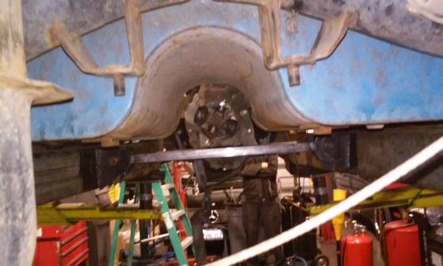
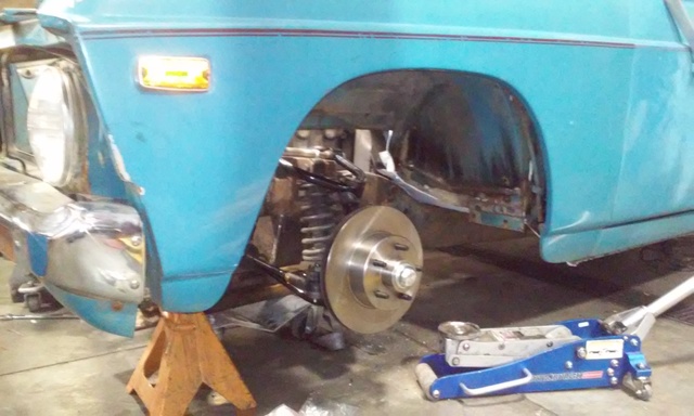
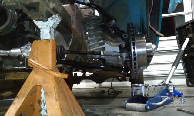
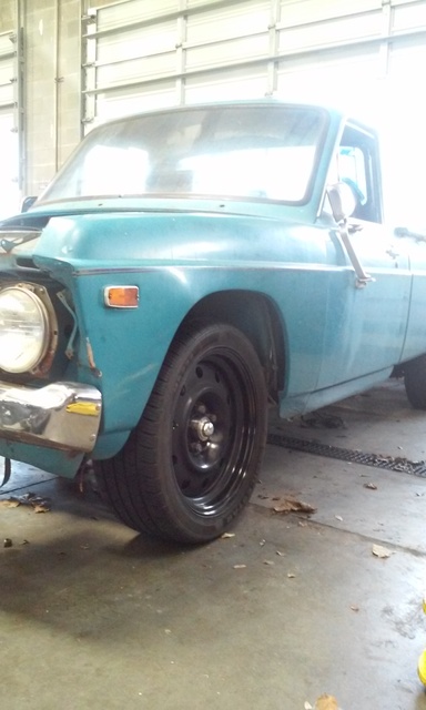
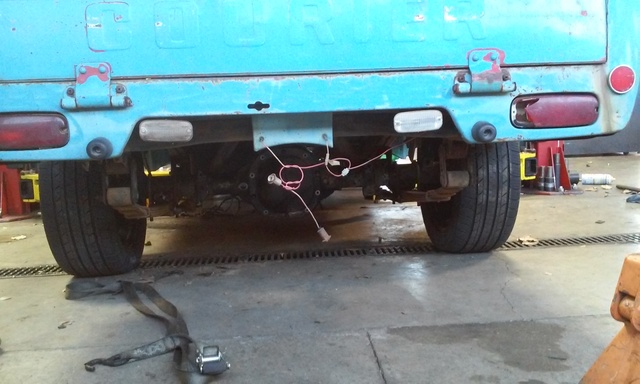
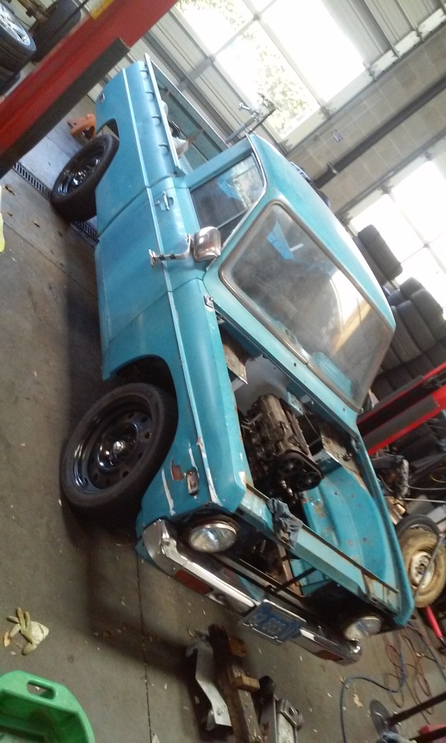
doing some more assembly. the truck is a bit lighter than i expected it to be. it cant even compress one jaguar rear coil spring(jags have 2 per side). the shocks just stay topped out and dont even sag when i stand on the front bumper. narrowing the axle made the spring perches the perfect width to bolt it back up to the leaf springs for mock up. feels good to see this thing back on its own wheels after 9 months.
Reply
0
0
08-17-2016, 09:26 PM
#20
Senior Member
Thread Starter
Join Date: Jan 2011
Location: sacramento ,ca
Posts: 563
Total Cats: 160
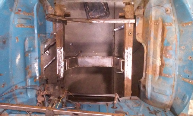
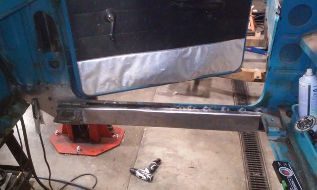
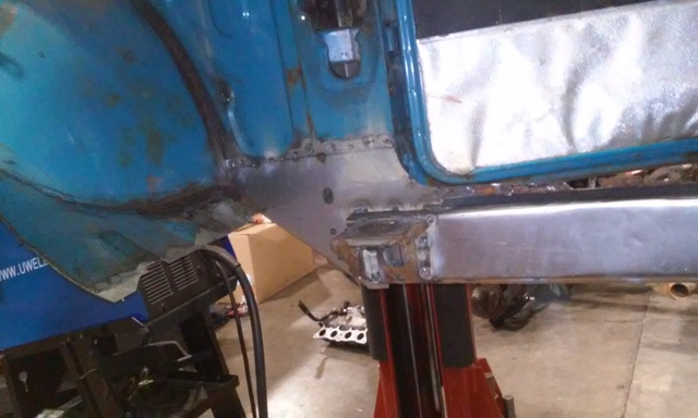
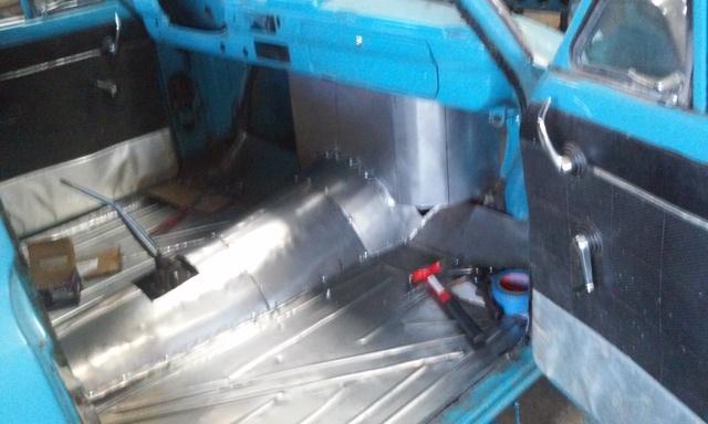
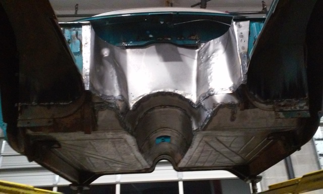
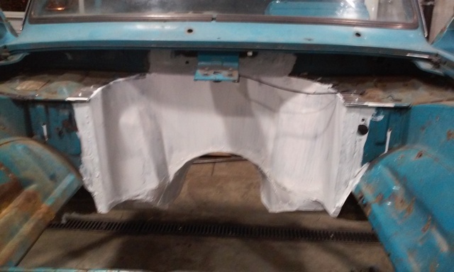
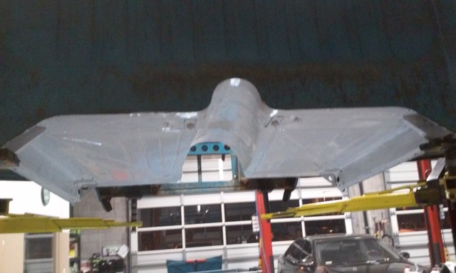
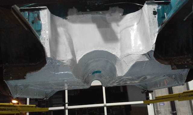
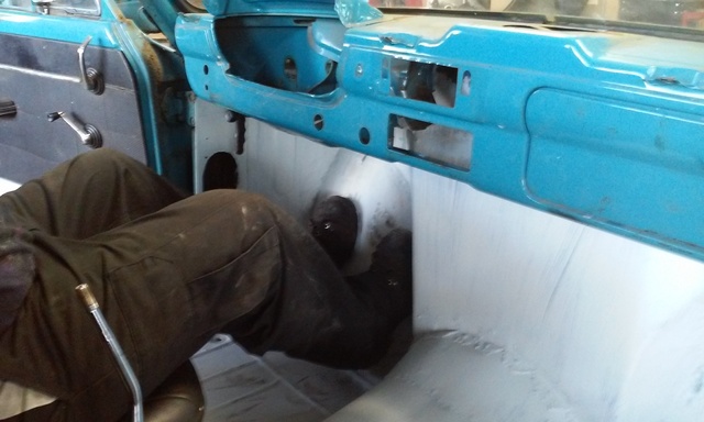
almost done with the fire wall
passenger side finally done
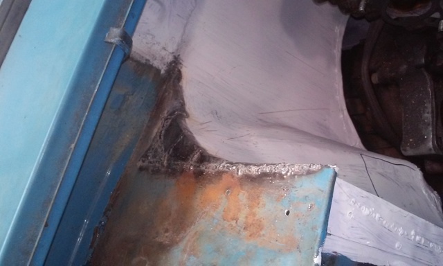
steering support in place and basic shape of teh drivers pedal area worked out
extended floor piece for the gas pedal shaped out
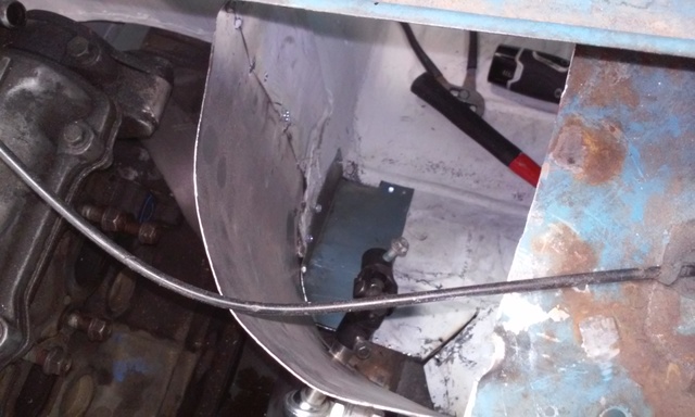
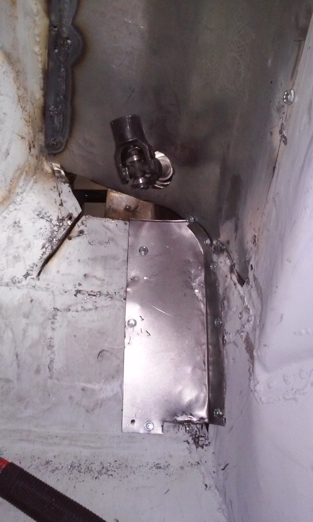
all welded in
passenger side finally done
steering support in place and basic shape of teh drivers pedal area worked out
extended floor piece for the gas pedal shaped out
all welded in
Reply
0
0


