Winter Turbo Build - Custom Equal Length Tial V-band Goodness!


 12-05-2011, 12:06 PM
#22

It's not really much of a jig to be honest - its just a flat plate with a piece of square tube tacked to it. The plate has some holes/slots so it can bolt to the base of the chop saw and the angle can be adjusted slightly. Then I just clamp the pipe against the square tube with some c-clamps. The hard parts are
1) You have to be able to rotate the pipe a precise amount (depending on the collector angle - I think mine was 86 degrees rotation or something...I used SW to figure it all out!). I used a rotating bubble level for this, and cut a notch in the end of the pipe so I had a flat surface to strap the bubble level thingy to.
2) You have to control how far into the saw the pipe goes - ie if you move the pipe 1/8" further into the saw when you unclamp, rotate and re-clamp it, it wont turn out right.
3) Blade deflection is a biatch. I bought the best blade I could find (made for stainless, more expensive than average - I can get the details if you want) from McMaster Carr to speed up the cutting. Then I held a chunk of 2x4 against the side of the blade as I was cutting (especially when starting the cut) to reduce blade wobble and deflection. Do it outside because the wood will smoke like crazy! Also I use a 12" blade even though the saw is 14" because it reduces deflection. After the cut was complete I just kept sweeping the saw up and down against the piece (while applying pressure with said 2x4 when necessary) to clean up the cut and make sure it was parallel to the the blade as it sits naturally. I spent hours doing that...
By the way this is the very first collector/manifold I have ever made, and i only scrapped one extra collector piece because the cut was wrong!

Reply
 0
0

0
 12-05-2011, 02:54 PM
#25
I use inventor, not solidworks but I have always struggled with
Making manifolds and things. Not the type of design work I usually do at my job. How do you make the manifold in cad? Treat each bend as a part ? What kind of tools do you use in sw to measure runner length?
Making manifolds and things. Not the type of design work I usually do at my job. How do you make the manifold in cad? Treat each bend as a part ? What kind of tools do you use in sw to measure runner length?
Reply
0
0
12-06-2011, 08:16 AM
#28
Junior Member
Thread Starter
iTrader: (2)

Join Date: Jul 2011
Location: Grand Rapids, MI
Posts: 213
Total Cats: 48

Seriously though, its funny that you ask becuase I just posted a topic about welding:
https://www.miataturbo.net/diy-turbo-discussion-14/tips-tig-welding-thin-walled-stainless-please-61982/
Reply
1
1
12-06-2011, 08:28 AM
#29
Junior Member
Thread Starter
iTrader: (2)
Join Date: Jul 2011
Location: Grand Rapids, MI
Posts: 213
Total Cats: 48
Hmm, I had a similar setup the last time I cut collectors with my chop saw. You seem to have figured out ways around all the problems I had. I think blade deflection and getting the cut depth correct was the biggest bitch for me. Thanks for the details. I'm going to give it a shot again here soonish. I would like details on that blade if you wouldn't mind.
The blade is from McMaster Carr, part number 4173A71. It is made by SAIT.
http://www.mcmaster.com/#cutoff-wheels/=f8svcf
I think the biggest thing is, once you finish the cut, put the blade down so it is past the part, get eye level with it and see if the blade surface is contacting the whole face of the cut. If it is only touching the part toward the bottom, and there is daylight at the top of the part then the blade deflected while cutting. That's when you start finessing it by sweeping the blade up and down and applying a side load with the 2x4. Obviously it is best if you can get it to cut straight the first time though, which I found requires a considerable amount of steady side pressure with the 2x4. Go slow. The more agressive, smaller 12" blade helps too - when I first started I was using a 14" Ryobi blade that came with the saw which obviously wasnt the best (in fact I did the whole thing with that blade, I didn't get the new one until I started trimming the collector and cutting the other straight pieces but I could tell that it cuts far better).
Reply
0
0
12-06-2011, 06:48 PM
#31
Thats becuase I only took pictures of the good ones
Seriously though, its funny that you ask becuase I just posted a topic about welding:
https://www.miataturbo.net/showthread.php?t=61982
Seriously though, its funny that you ask becuase I just posted a topic about welding:
https://www.miataturbo.net/showthread.php?t=61982
Good luck with the rest of your build!
Reply
0
0
12-07-2011, 12:31 AM
#33
Junior Member
Thread Starter
iTrader: (2)
Join Date: Jul 2011
Location: Grand Rapids, MI
Posts: 213
Total Cats: 48
I use inventor, not solidworks but I have always struggled with
Making manifolds and things. Not the type of design work I usually do at my job. How do you make the manifold in cad? Treat each bend as a part ? What kind of tools do you use in sw to measure runner length?
Making manifolds and things. Not the type of design work I usually do at my job. How do you make the manifold in cad? Treat each bend as a part ? What kind of tools do you use in sw to measure runner length?
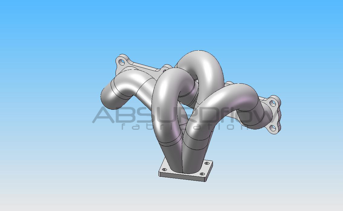
I first modeled the flanges (head flange and v-band). Then I modeled the collector/v-band as a sub assembly, and put it into a final assembly along with the head flange and positioned to the two in space relative to one another based on the coordinates that I determined with a wooden mockup in the car. Then I modeled each of the four runners "in context" within the assembly, so that changing the position/angle/rotation of the collector (even the merge angle) in spatial relation to the head flange would cause the runners to automatically update. In this manner the assembly is "intelligent" so I can explore different options without remodeling everything.
Each runner is basically a profile sketch and a 3D path sketch to form a sweep. If you are careful when making the 3D sketch, you can ensure that each bend fits within the 90 degree limitation of weld elbows - i.e. if you create a bend that needs to be 185 degrees, it's probably a bad idea because you will then need two 90's plus a 5 degree sliver! All you need to do to determine runner length is measure the length of the line segment in the 3D path sketch. Then just keep tweaking the sketches and other parameters until all runners are equal.
After that I took it a step further and modeled each individual pipe/elbow in context of the assembly based off the individual line segments of the 3D sketches of the four individual runners. This let me make a 1:1 scale drawing of each individual part (very handy because you can lay an elbow on the paper and trim it exactly until you achieve the correct bend angle), and even group them into sub assemblies to explore different assembly sequences and determine which parts I could weld up first before trimming them and welding them into the final assembly.
I *almost* went to the extent of modeling my TIG torch to see how it well it would fit into various places, but then I realized that my OCD was kicking in and said **** it.
Then I modeled the welding fixture in context of the assembly, and fabricated it on the mill in our machine shop at work. Surprisingly, I was able to pre-cut all of the pieces, and only had to trim two of them a hair when I started to do the final assembly. So essentially, I can say with a high level of confidence that the runners are equal length to within about .060" or so.
If I had access to the flow simulation add-in for SolidWorks, I would have strongly considered doing a flow analysis. As JKav states, equal length is not as important as equal flow!
I will say this: when making a manifold of this intricacy, order of operations is KEY.
I hope at least some of the above makes sense. Finishing a very strong whiskey and Coke as I type this. At least those versed in SolidWorks might understand it.
Last edited by mx592; 12-07-2011 at 12:42 AM.
Reply
2
2
12-07-2011, 01:39 AM
#34
Elite Member
iTrader: (2)

Join Date: Jan 2007
Location: Los Angeles, CA
Posts: 8,682
Total Cats: 130
To be honest I used a rather complicated technique, and I'm not sure how much of it would be comparable between Inventor and SolidWorks. But if you must know...
I first modeled the flanges (head flange and v-band). Then I modeled the collector/v-band as a sub assembly, and put it into a final assembly along with the head flange and positioned to the two in space relative to one another based on the coordinates that I determined with a wooden mockup in the car. Then I modeled each of the four runners "in context" within the assembly, so that changing the position/angle/rotation of the collector (even the merge angle) in spatial relation to the head flange would cause the runners to automatically update. In this manner the assembly is "intelligent" so I can explore different options without remodeling everything.
Each runner is basically a profile sketch and a 3D path sketch to form a sweep. If you are careful when making the 3D sketch, you can ensure that each bend fits within the 90 degree limitation of weld elbows - i.e. if you create a bend that needs to be 185 degrees, it's probably a bad idea because you will then need two 90's plus a 5 degree sliver! All you need to do to determine runner length is measure the length of the line segment in the 3D path sketch. Then just keep tweaking the sketches and other parameters until all runners are equal.
After that I took it a step further and modeled each individual pipe/elbow in context of the assembly based off the individual line segments of the 3D sketches of the four individual runners. This let me make a 1:1 scale drawing of each individual part (very handy because you can lay an elbow on the paper and trim it exactly until you achieve the correct bend angle), and even group them into sub assemblies to explore different assembly sequences and determine which parts I could weld up first before trimming them and welding them into the final assembly.
I *almost* went to the extent of modeling my TIG torch to see how it well it would fit into various places, but then I realized that my OCD was kicking in and said **** it.
Then I modeled the welding fixture in context of the assembly, and fabricated it on the mill in our machine shop at work. Surprisingly, I was able to pre-cut all of the pieces, and only had to trim two of them a hair when I started to do the final assembly. So essentially, I can say with a high level of confidence that the runners are equal length to within about .060" or so.
If I had access to the flow simulation add-in for SolidWorks, I would have strongly considered doing a flow analysis. As JKav states, equal length is not as important as equal flow!
I will say this: when making a manifold of this intricacy, order of operations is KEY.
I hope at least some of the above makes sense. Finishing a very strong whiskey and Coke as I type this. At least those versed in SolidWorks might understand it.
Reply
0
0

 12-08-2011, 07:29 PM
#36
Elite Member
iTrader: (2)

Join Date: May 2007
Location: Cromwell, Connecticut
Posts: 2,604
Total Cats: 16
To be honest I used a rather complicated technique, and I'm not sure how much of it would be comparable between Inventor and SolidWorks. But if you must know...
I first modeled the flanges (head flange and v-band). Then I modeled the collector/v-band as a sub assembly, and put it into a final assembly along with the head flange and positioned to the two in space relative to one another based on the coordinates that I determined with a wooden mockup in the car. Then I modeled each of the four runners "in context" within the assembly, so that changing the position/angle/rotation of the collector (even the merge angle) in spatial relation to the head flange would cause the runners to automatically update. In this manner the assembly is "intelligent" so I can explore different options without remodeling everything.
Each runner is basically a profile sketch and a 3D path sketch to form a sweep. If you are careful when making the 3D sketch, you can ensure that each bend fits within the 90 degree limitation of weld elbows - i.e. if you create a bend that needs to be 185 degrees, it's probably a bad idea because you will then need two 90's plus a 5 degree sliver! All you need to do to determine runner length is measure the length of the line segment in the 3D path sketch. Then just keep tweaking the sketches and other parameters until all runners are equal.
After that I took it a step further and modeled each individual pipe/elbow in context of the assembly based off the individual line segments of the 3D sketches of the four individual runners. This let me make a 1:1 scale drawing of each individual part (very handy because you can lay an elbow on the paper and trim it exactly until you achieve the correct bend angle), and even group them into sub assemblies to explore different assembly sequences and determine which parts I could weld up first before trimming them and welding them into the final assembly.
I *almost* went to the extent of modeling my TIG torch to see how it well it would fit into various places, but then I realized that my OCD was kicking in and said **** it.
Then I modeled the welding fixture in context of the assembly, and fabricated it on the mill in our machine shop at work. Surprisingly, I was able to pre-cut all of the pieces, and only had to trim two of them a hair when I started to do the final assembly. So essentially, I can say with a high level of confidence that the runners are equal length to within about .060" or so.
If I had access to the flow simulation add-in for SolidWorks, I would have strongly considered doing a flow analysis. As JKav states, equal length is not as important as equal flow!
I will say this: when making a manifold of this intricacy, order of operations is KEY.
I hope at least some of the above makes sense. Finishing a very strong whiskey and Coke as I type this. At least those versed in SolidWorks might understand it.
I first modeled the flanges (head flange and v-band). Then I modeled the collector/v-band as a sub assembly, and put it into a final assembly along with the head flange and positioned to the two in space relative to one another based on the coordinates that I determined with a wooden mockup in the car. Then I modeled each of the four runners "in context" within the assembly, so that changing the position/angle/rotation of the collector (even the merge angle) in spatial relation to the head flange would cause the runners to automatically update. In this manner the assembly is "intelligent" so I can explore different options without remodeling everything.
Each runner is basically a profile sketch and a 3D path sketch to form a sweep. If you are careful when making the 3D sketch, you can ensure that each bend fits within the 90 degree limitation of weld elbows - i.e. if you create a bend that needs to be 185 degrees, it's probably a bad idea because you will then need two 90's plus a 5 degree sliver! All you need to do to determine runner length is measure the length of the line segment in the 3D path sketch. Then just keep tweaking the sketches and other parameters until all runners are equal.
After that I took it a step further and modeled each individual pipe/elbow in context of the assembly based off the individual line segments of the 3D sketches of the four individual runners. This let me make a 1:1 scale drawing of each individual part (very handy because you can lay an elbow on the paper and trim it exactly until you achieve the correct bend angle), and even group them into sub assemblies to explore different assembly sequences and determine which parts I could weld up first before trimming them and welding them into the final assembly.
I *almost* went to the extent of modeling my TIG torch to see how it well it would fit into various places, but then I realized that my OCD was kicking in and said **** it.
Then I modeled the welding fixture in context of the assembly, and fabricated it on the mill in our machine shop at work. Surprisingly, I was able to pre-cut all of the pieces, and only had to trim two of them a hair when I started to do the final assembly. So essentially, I can say with a high level of confidence that the runners are equal length to within about .060" or so.
If I had access to the flow simulation add-in for SolidWorks, I would have strongly considered doing a flow analysis. As JKav states, equal length is not as important as equal flow!
I will say this: when making a manifold of this intricacy, order of operations is KEY.
I hope at least some of the above makes sense. Finishing a very strong whiskey and Coke as I type this. At least those versed in SolidWorks might understand it.
I have inventors add-in for fluid analysis. I havent messed with it too much, but I used a bit of CFD in college, so I might be able to play around with your manifold for ***** if you want to send me a step or iges file. Not sure how all the surfaces will convert, but its worth a shot.
PM me if you want.
Reply
0
0
12-08-2011, 11:27 PM
#37
Elite Member

iTrader: (9)
Join Date: Jun 2006
Location: Chesterfield, NJ
Posts: 6,892
Total Cats: 399
This is the first I've seen this thread, excellent job. I am impressed. It makes my stuff look ghetto!
-Polishing those weld elbows must have taken an incredible amount of time. I can't fathom that. Just taking them to the wire wheel takes too long.
-Very nice weld fixture.
-I am also impressed you were able to cut the collector with a chop saw (my tool of choice cause i'm impatient). I never tried, but in my mine it wasn't possible while keeping your fingers or not scrapping a lot of material. I use a horizontal band saw and tack the pipe to a fixture. I do the first cut on each of the 4 pipes, tack pairs together, cut the second cut on each pair, then tack together the full collector, cause the angle from one cut to the other on each indivitual pipe isn't the same for my collectors (i.e. the axis of each pipe does not point to the same spot within the flange).
-I am glad to see the use of Solidworks and an explaination of it's use, along with your full process. I'm glad I'm not the only one whipping up wooden mockups first.
I have tried to model manifolds within solidworks a few different ways, but my current method is perhaps slightly different than yours. I do not have much experience defining parts within an assembly; not sure why, but it's a pet pieve of mine. Perhaps cause a co-worker does it daily, then explodes the relations and fixes everything so you can't ever modify anything easily. Anyway...I will have to try your method, it may be easier.
With the exception of the flanges, my manifolds are modeled within a single part file using individual 3D sketches for each primary pipe path, starting at a sketch that is the head flange geometry (which also doubles as the cross section sketch for the swept 'feature'/pipe) and ending at the entry location of the collector. Within each individual primary pipe's 3D path sketch are however many 2D sketch planes needed (I try to limit it to 3 or 4) to define the path within the confines of whatever weld elbow geometry you have available (i.e. 2.25" and 1.5" radii for 1.5" pipe). Therefore I often do use greater angles than 90deg. Pipes and straights that are tangent to each other and can be constrained/defined within a 2D plane (the 2D sketch planes in this case) are done so, and the angles between each 2D sketch plane or sketch plane and the datum define the pipe's shape. Again, this is done within the individual 3D sketch of each primary tube. Once each primary path is done, I sweep the cross section and the rest is easy. So far I use only 1 collector because, for me, it was a PITA and confusing to get the angles out of it for the cut fixture.
Wait, what?
It can get real messy, real quick. Solidworks likes to flip the constraints over on you making stuff all sorts of crazy. I save often. It takes a computer more powerful than the one I have at home to do it right but I still manage somehow...i need to find a better way It doesn't help that I have SW2007 at home and 2011 at work, so I can't open work's files at home. I have to try to remember what worked and redo it (with the wife's trackball...ugh). I mean, I can move/rotate/angle the collector flange within it's defined parameters and hit refresh and, within reason, it will update just fine, but ideally I'd like to also be able to grab each primary pipe and drag it real-time. I think using a "flexible" assembly process with individual bend/straight sections may be able to do this...
Are you using all 2.25" radius bends? Christ man, very nice. This has my vote on best flowing equal length mani to date. I had to use some 1.5" radii bends on Lars' to get it 'equal' within .020" theoretically (14.350" OAL), whereas the all 2.25" radii version has 11.750" long 1 & 4 primaries.
Does it clear the hood?
-Polishing those weld elbows must have taken an incredible amount of time. I can't fathom that. Just taking them to the wire wheel takes too long.
-Very nice weld fixture.
-I am also impressed you were able to cut the collector with a chop saw (my tool of choice cause i'm impatient). I never tried, but in my mine it wasn't possible while keeping your fingers or not scrapping a lot of material. I use a horizontal band saw and tack the pipe to a fixture. I do the first cut on each of the 4 pipes, tack pairs together, cut the second cut on each pair, then tack together the full collector, cause the angle from one cut to the other on each indivitual pipe isn't the same for my collectors (i.e. the axis of each pipe does not point to the same spot within the flange).
-I am glad to see the use of Solidworks and an explaination of it's use, along with your full process. I'm glad I'm not the only one whipping up wooden mockups first.
I have tried to model manifolds within solidworks a few different ways, but my current method is perhaps slightly different than yours. I do not have much experience defining parts within an assembly; not sure why, but it's a pet pieve of mine. Perhaps cause a co-worker does it daily, then explodes the relations and fixes everything so you can't ever modify anything easily. Anyway...I will have to try your method, it may be easier.
With the exception of the flanges, my manifolds are modeled within a single part file using individual 3D sketches for each primary pipe path, starting at a sketch that is the head flange geometry (which also doubles as the cross section sketch for the swept 'feature'/pipe) and ending at the entry location of the collector. Within each individual primary pipe's 3D path sketch are however many 2D sketch planes needed (I try to limit it to 3 or 4) to define the path within the confines of whatever weld elbow geometry you have available (i.e. 2.25" and 1.5" radii for 1.5" pipe). Therefore I often do use greater angles than 90deg. Pipes and straights that are tangent to each other and can be constrained/defined within a 2D plane (the 2D sketch planes in this case) are done so, and the angles between each 2D sketch plane or sketch plane and the datum define the pipe's shape. Again, this is done within the individual 3D sketch of each primary tube. Once each primary path is done, I sweep the cross section and the rest is easy. So far I use only 1 collector because, for me, it was a PITA and confusing to get the angles out of it for the cut fixture.
Wait, what?
It can get real messy, real quick. Solidworks likes to flip the constraints over on you making stuff all sorts of crazy. I save often. It takes a computer more powerful than the one I have at home to do it right but I still manage somehow...i need to find a better way
It doesn't help that I have SW2007 at home and 2011 at work, so I can't open work's files at home. I have to try to remember what worked and redo it (with the wife's trackball...ugh). I mean, I can move/rotate/angle the collector flange within it's defined parameters and hit refresh and, within reason, it will update just fine, but ideally I'd like to also be able to grab each primary pipe and drag it real-time. I think using a "flexible" assembly process with individual bend/straight sections may be able to do this...Are you using all 2.25" radius bends? Christ man, very nice. This has my vote on best flowing equal length mani to date. I had to use some 1.5" radii bends on Lars' to get it 'equal' within .020" theoretically (14.350" OAL), whereas the all 2.25" radii version has 11.750" long 1 & 4 primaries.
Does it clear the hood?
Last edited by TurboTim; 12-08-2011 at 11:39 PM.
Reply
1
1
12-08-2011, 11:33 PM
#38
Junior Member
Thread Starter
iTrader: (2)
Join Date: Jul 2011
Location: Grand Rapids, MI
Posts: 213
Total Cats: 48
Not sure if you would want it, because I know for a fact that the hole locations for the manifold studs are a bit off. They were close enough that the flange I bought from SLS still fit on my assembly jig (there was enough clearance in the hole of the flange to the 3/8" bolts I used, luckily).
Honestly its such a good deal to just buy one from SLS, I don't know if it would be worth your time to write the program and CNC one, even if you had the equipment?
Honestly its such a good deal to just buy one from SLS, I don't know if it would be worth your time to write the program and CNC one, even if you had the equipment?
Reply
0
0
 12-08-2011, 11:46 PM
#40
Elite Member
iTrader: (9)
Join Date: Jun 2006
Location: Chesterfield, NJ
Posts: 6,892
Total Cats: 399
Not sure if you would want it, because I know for a fact that the hole locations for the manifold studs are a bit off. They were close enough that the flange I bought from SLS still fit on my assembly jig (there was enough clearance in the hole of the flange to the 3/8" bolts I used, luckily).
Honestly its such a good deal to just buy one from SLS, I don't know if it would be worth your time to write the program and CNC one, even if you had the equipment?
Honestly its such a good deal to just buy one from SLS, I don't know if it would be worth your time to write the program and CNC one, even if you had the equipment?
Last edited by TurboTim; 12-08-2011 at 11:58 PM.
Reply
0
0


