When you click on links to various merchants on this site and make a purchase, this can result in this site earning a commission. Affiliate programs and affiliations include, but are not limited to, the eBay Partner Network.
Holidays have been busy but I've progressed the build enough for an update. I've spent quite a bit of time refining and finishing a few things. Got the O2 bung in the downpipe, cut off and rewelded the radiator front mounts to make room for the rubber isolators, added reflective insulation to the nose piece, finished up the radiator intake piping ect. ect. Small stuff just eats up the time.
I did get a good start on the exit ducting.
Found this little jewel which I found hilarious since the corner is burnt from welding.
Then I laid out for the ducting exit.......
I stared at it for a couple of days and then took the plunge.
I hand bent the opening, not entirely happy with the radius on the long section but it isn't bad. The hood bulge prevented me from starting any further back, it would have look better with a long sweeping bend and I had another 3-4" to the head. Just figured trying to bend the bulge would end badly.
I was pretty happy with how much bracing was left underneath, this is a steel replacement hood so really this is a dry run for when I get my hands on a stock aluminum hood.
I still need to work out the interface between the hood opening and the HPDE ducting but overall it's looks like it'll work out well.
That's similar to what I have plans to do, but mine is simpler because my needs are less. I plan to exit the radiator in the normal manner, and bring the exit of the IC under the radiator and then back up into the engine compartment. I, too, have a bunch of the HDPE to use for ducting. I bought way too much of it. Here is a quick sketch of what I have in mind. Reason, presently flowing all air through all three exchangers seems to be restricting the total flow. AIT is fine, but A/C at 40 mph caused overheating in the summer.
Great Thread
EDIT: How have you decided to duct the outlet of the FMIC?
From a pure cooling aspect your plans will probably work just fine. One of the other big benefits to ducting all the cooling air out the hood is a substantial reduction in lift on the front end.
If you look close you can see a 2" gap been the sway bar and the back wall of my ductwork, this is where the intercooler flow will rejoin the radiator flow.
Thanks. I see. Lift was pointed out to me when I was going to simply let the IC outlet go directly down at the front of the car. That is why I plan to bring it back above the under tray. That way I don't gain like you will, but I shouldn't go the other way, either.
Well the exit path will be down the trans tunnel not sure in front of the crossmember or behind will make a ton of difference. I mean it's all conjecture on my part, heck all this work to duct the air out the hood might result in 20 lb. of lift reduction and cool no better. There does seem to be plenty of data points that simply popping a hole in the hood improves cooling so reason would dictate this approach would be closer to ideal.
Wiring....... Yeah a lot of that to do, going to repurpose all the emissions junk wiring to pick up oil temp, oil pressure, sequential ignition and fuel pressure.
As long as the no name coils aren't junk I'm going to be 45$ into this COP conversion.
There was a nice flat spot on the fuel rail to drill and tap for a pressure sensor. It's at the end of the rail near the pulsation damper so it should be the lowest pressure point in the system.
Life has been getting in the way lately, I was able to finish up my under hood wiring. I repurposed wires from the EGR, VICS, and rear O2 sensor to bring back signals for all the new fun stuff such as seq. IGN., Oil temp, oil pressure, fuel pressure. I then wrapped the harness with this cool Tess brand cloth tape. Evidently is OE on a bunch of German cars.
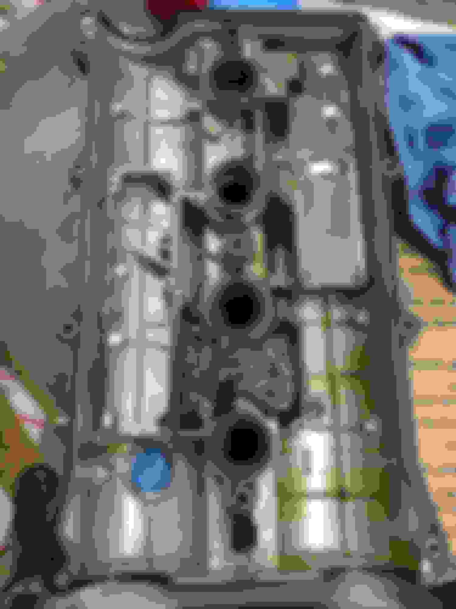
I then turned my attention to the valve cover and crankcase vent system which I honestly had overlooked until I stumbled onto a thread here. I started by drilling out the factory baffle hole to 5/16" and added another for good measure. I'm going to try to use the factory vent nipple but if I have issues I'll enlarge it to 1/2". I also added some stainless steel wool at the entrance to the first baffle chamber. This should give plenty of surface area for oil to cling to.
I ordered an eBay baffled and vented catch can but after looking at it I think I'm going to chop it up. Baffling is all wrong with the ports above the baffling, vent filter is stripped and choked in size, it's just a hot mess. I'm planning on plugging the PCV vent because the baffling is no where near as robust as the hot side vent.
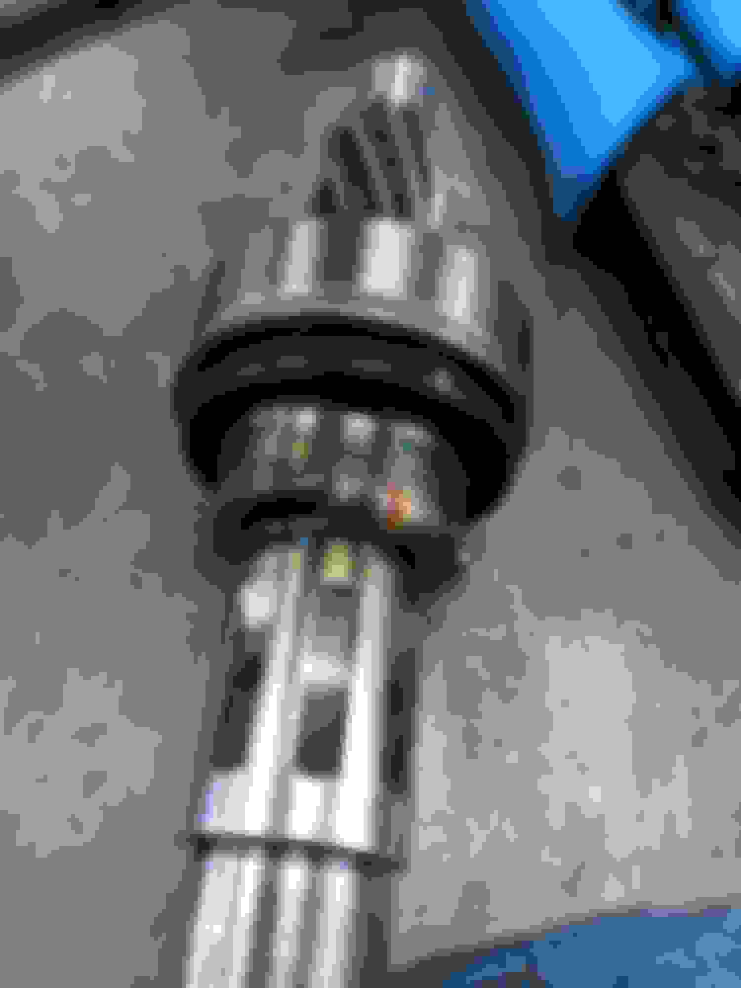
I was running a factory spec thermostat and it always bothered me how small the port was on it. So I ordered this high Flow motorad unit and drilled out the togler holes to allow a substantial amount of bypass flow.
So I have a theory that goes against a lot of commonly accepted believe here. I firmly believe you can't have too much flow when running full tilt, I even believe running without a thermostat can help, but introduces a ton of issues with warm up, tunning for wild temp swings and the need to run a higher pressure radiator cap to make up for the fact that the restrictive thermostat isn't raising the pressure in the block.
The compromise I'm using is this high Flow thermostat with large bypasses, I'm also running a 180 deg thermostat, but not because 195 is too hot but just the fact that at my target of 200deg the 180 will be open further than the 195.
I also got started ony COP mounts and threw some paint at the valve cover.
AN-6 line are a pain in the dick, ended up making one of those tapered sleeves you can buy because there is no way to cut that small braided line without it flaring out. I didn't grab a pic of the line but it's nothing fancy.
Then I drilled a big honking hole in the pan.
that's a 3/8" NPT x 5/8" hose adapter and the ID is strait through for high Flow.
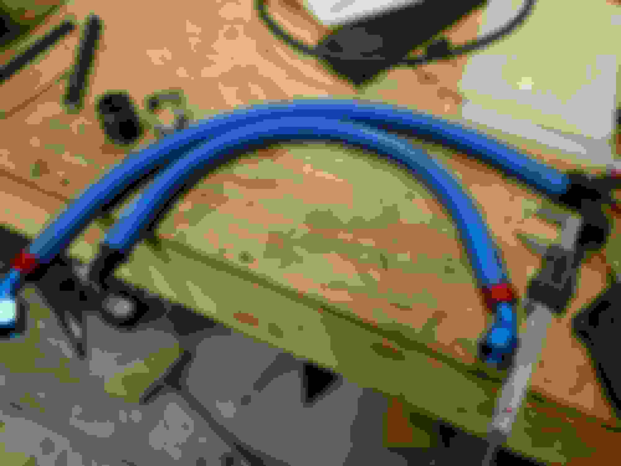
I then turned to the oil cooler and lines. I went with pushlock hose and fittings. There's a miss mash if brands and colors because I bought whatever was cheap. I would have rather not used 90's for flow but there was no escaping it with that cooler size.
I finished up the cooler ducting, the hole lines up perfectly with the fog light beazel so it actually inserts into the opening. I hit the easy button on the exit ducting and just used a splash guard to keep the tires from slinging rocks onto the cooler. I'm banking on the fact the air coming through the fog light beazel will be at a higher pressure than the wheel well.....If I have high temps I'll duct the exit somewhere with low pressure.
Ii figured out a way to weld the HPDE sheeting, it's ugly but it works. A hot air plastic welding setup would be better but I just needed a few tacks to hold the sides in place.
I basically took a pice of filler rod and heated it up with a torch and then used the heat to fuse the two pieces of plastic together. It takes bending the joint backwards to break this "weld".
Also depowered the rack and made a few shims to limit steering travel since I was rubbing the springs at full lock.
Nice work on the HDPE adaption for your cooler ducting. I'm just about to attemp something similar with this material to duct my oil cooler.
I've been experimenting with shaping it with heat and in think mine will probably end up being held together using tabs folded at right angles and rivets. The photo is of one of my experiments...
So, I saw this in another thread, that steel wool will become dust or something, and damage stuff. Maybe copper scrubbie, being more ductile, wont dust as easily.
Again, not sure if this is true, just something to look into, as it could become a larger problem.
On the HPDE, I did something similar on the radiator ducting but for curved surfaces the welding seemed like a good option. I still have the exit ducting to do on the radiator, think I'll leave tabs every couple inches for the curved portion.
I was worried about the wool ending up where it shouldn't..The stuff I used was stainless and the wider type at that, it's almost like ribbon. I'll probably keep an eye on it for a while, thanks for the heads up.
So, I saw this in another thread, that steel wool will become dust or something, and damage stuff. Maybe copper scrubbie, being more ductile, wont dust as easily.
Again, not sure if this is true, just something to look into, as it could become a larger problem.
Ryan G's build thread.
He opened the engine up again after we freaked him out about that and found that there were small pieces of the steel wool dust that were hanging out.
He opened the engine up again after we freaked him out about that and found that there were small pieces of the steel wool dust that were hanging out.
Thanks for the heads up, I checked out his thread and it appears he's using a fine wool. I'm using the heavy scrubbing type, the stuff was tough to cut so I think it'll be OK. I'll be keeping an eye on it for sure.
I also don't like how he completely filled the cavity with it. In my mind the oil would be able to travel through the wool to the outlets, I just wanted a short section to give the oil a place to condense, it would have to turn back into a mist and travel through both chambers to get to the outlet.
Been thrashing to get this thing done..... one step forward and two back. So I nicked a tube on the radiator, no big deal I've got a TIG I said......ugh. It's literally like trying to weld pop cans together while standing on your head with no room. That turned into a mighty cluster **** that had me thinking of starting over with a new radiator at one point. In the end I found it just easiest to open up the hole slightly, fill it with JB weld and then smashing the tube around the opening to pinch the epoxy. If you're careful you can even save part of the tube to allow some flow. With this new found knowledge I picked up some quick 1 hour aluminum epoxy to keep in the tool box. I didn't take any pictures of this mess......still trying to forget. Then I found I pinched the gasket with the thermostat and got to **** with that again, see I had thought ahead and tightened the bolts the first time when I had the trans out and the motor leaned forward, had plenty of room then, now not so much.
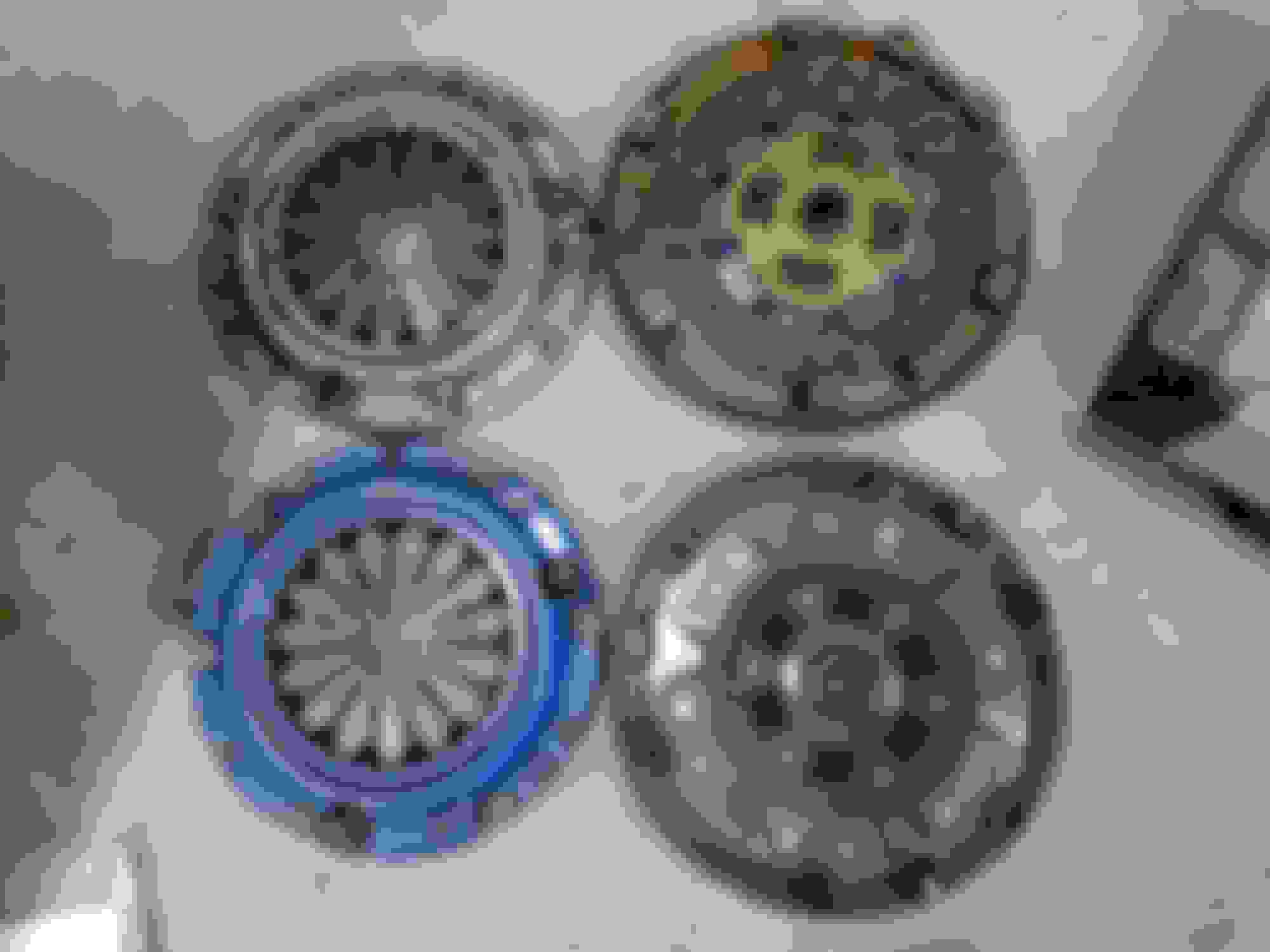
On to actual progress, swapped clutches to a Spec sprung 6 puck and whatever this is pressure plate, think it's a stage 3. I have 150$ in this lightly used clutch and another 100$ in a 12 lb. flywheel. Interestingly enough this clutch weighed 2 lb's more than the stock exeedy so only ended up dropping 4 lb's. All that additonal weight was in the clutch disk too, has to be in the beefy hub.
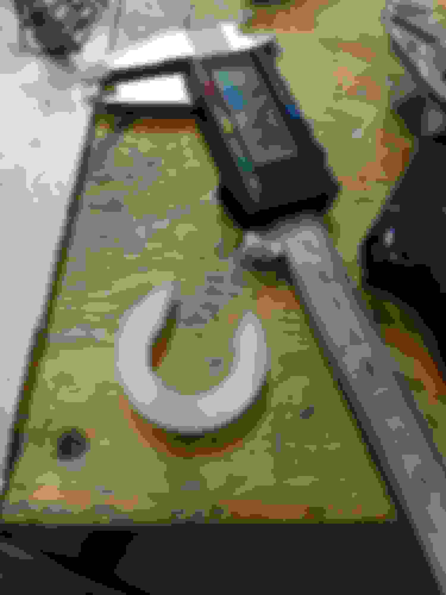
I also made this tail shaft plug for my tranny to prevent any unwanted dripping lube while I wrestled around with it on the floor..........(insert gay joke here)
I went ahead and insulated the tunnel while I had the trans out, this is the lowes duct insulation everyone on here talks about. It does take some extra spray adhesive to get it to stick well but I have high hopes for it and man is it cheap. I did a little test where I put a piece on some sheet metal and put a propane torch to on it. It took over 60 seconds of direct heat before I could feel any warmth at all, by that point the aluminum foil had melted and the foam was starting to burn. Because this is designed for duct installation one of the requirements is that it be self extinguishing, this doesn't mean it's fire proof, but it does mean it will stop burning when the flame is removed from it. I can confirm this is the case, so if you start a fire under your car this won't make it any worse and without direct flame it will never burn.
Made some changes to the wiring in the DIY BOB.
Now onto my last problem that I hope really isn't a problem. As you can see in this video the turbo doesn't turn well or at all at idle. It's got some noticable resistance when you turn the blades by hand with the car off, nothing crazy, you can turn it with your pinky but it sure isn't free. This is a journal bearing turbo that has sat for a few years, I'm pretty sure the oil in the bearings has gummed up a bit and I'm hoping with a heat cycle or two and plenty of fresh oil flowing it'll clean itself up.......wishful thinking? I did confirm it's getting oil by popping off the drain line. Car runs like ***, but with a little blipping of the throttle to 3 grand the BOV pops and makes whooshing noises so it's moving some air in this state.
It's been a frustrating couple of weeks but I finally had a break through today. The turbo free'd up and now spins easily by hand once I was able to get the revs up and spin the turbo at high RPM. Got lucky there. I've also been battling a sync issue, no matter what I do I can't get the voltages on the POT's right, have no idea what's going on there but at this point it seems to have just magically fixed itself. I'll take a mystery fix at this point.
I slapped the nose on for the last time got it off the jack stands for the first time in many months and took her on her maiden voyage......and promptly broke it. Evidently I had the ports wrong on the boost controler, Saw 17 psi for a split second before I decided bring it back in and rectify the issue. Got overboost protection working now. That one shot to 17psi was enough to kill a coil, whether it was the high boost or just a fluke the coil died almost exactly as the boost spiked. Guess the 35$ ebay coils weren't so great after all. Picked up a coil, fixed the EBC and she runs much better now. It didn't take long to get the VE table trued up and was able to play around with it at 6 psi. Wow.....I knew it was going to good but it's really good. Can't wait to creep my way up to full power.
So I found another problem, I was at 160 deg F water temp before I left the driveway and once I was up to speed the temps dropped to 120. Damn radiator and ducting work so well the two 1/4" holes I drilled in the thermostat pass enough water to over cool the engine. So I get to pull the thermostat housing off yet again. Oil cooler worked really well too, never moved above 80 degrees. Granted it was in the low 40's out, but this is a pretty good indicator that it'll be just fine on track. I'd like to see oil temps up to 150 degrees minumum.


 12-30-2016, 10:49 AM


 0
0