COP Thread

 09-18-2014, 09:21 AM
#1722
Same here, I've got at least one flakey coil now after running them in batch for quite a while off the stock ECU. I really wish we could get a dwell reducer that actually works. I think I have about 10 coils in the garage now, its going to suck when I finally get around to figuring out how to test them.
Also, the car idled way smoother on the cops than it did on the factory coilpack, even on the stock ECU.
Also, the car idled way smoother on the cops than it did on the factory coilpack, even on the stock ECU.
Necro-quote, but was this misfire without rhyme or reason?
I'm running in batch, but there's a big resistor thing in the harness. Been fighting a completely random misfire.

Reply
 0
0

0
09-18-2014, 01:16 PM
#1723
Elite Member
iTrader: (37)

Join Date: Apr 2010
Location: Very NorCal
Posts: 10,441
Total Cats: 1,899
It had rhyme and reason, but solving it was suck. It only really did it when hot, so I'd have to drive it until things got hot and then sit on the side of the road swapping with a spare until it went away. Easy peasy.
What's the resistor for? I don't remember seeing that in any of the writeups.
What's the resistor for? I don't remember seeing that in any of the writeups.
Reply
0
0
12-06-2014, 02:42 PM
#1724

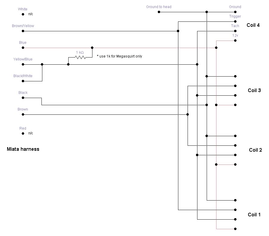
Would it be ok to solder the 1Kohm resistor inside the igniter box between the blue and yellow/blue from one spade to the other? That would keep the resistor from becoming damaged and/or breaking.
Also, I got a set of resistors at Radio Shack, they say "1k ohm, 1/4watt carbon film resistor", is this the right one?
And, do I really need to add the 10000uf capacitor to the 12v and ground?
Thanks!
Also, I got a set of resistors at Radio Shack, they say "1k ohm, 1/4watt carbon film resistor", is this the right one?
And, do I really need to add the 10000uf capacitor to the 12v and ground?
Thanks!
Last edited by btabor; 12-06-2014 at 03:10 PM.
Reply
0
0
12-06-2014, 03:47 PM
#1725
Boost Czar


Thread Starter
iTrader: (62)
Join Date: May 2005
Location: Chantilly, VA
Posts: 79,493
Total Cats: 4,080
Would it be ok to solder the 1Kohm resistor inside the igniter box between the blue and yellow/blue from one spade to the other? That would keep the resistor from becoming damaged and/or breaking.
Also, I got a set of resistors at Radio Shack, they say "1k ohm, 1/4watt carbon film resistor", is this the right one?
And, do I really need to add the 10000uf capacitor to the 12v and ground?
Thanks!
Cap is not needed
Reply
0
0
12-06-2014, 04:58 PM
#1726
I have MSPNP1
What I dont understand is why that schematic shows the resistor bridging blue and yellow/blue, why not just place the resistor between the yellow/blue and white black instead?
Last edited by btabor; 12-06-2014 at 05:13 PM.
Reply
0
0
12-06-2014, 06:05 PM
#1728
SADFab Destructive Testing Engineer

iTrader: (5)
Join Date: Apr 2014
Location: Beaverton, USA
Posts: 18,642
Total Cats: 1,866
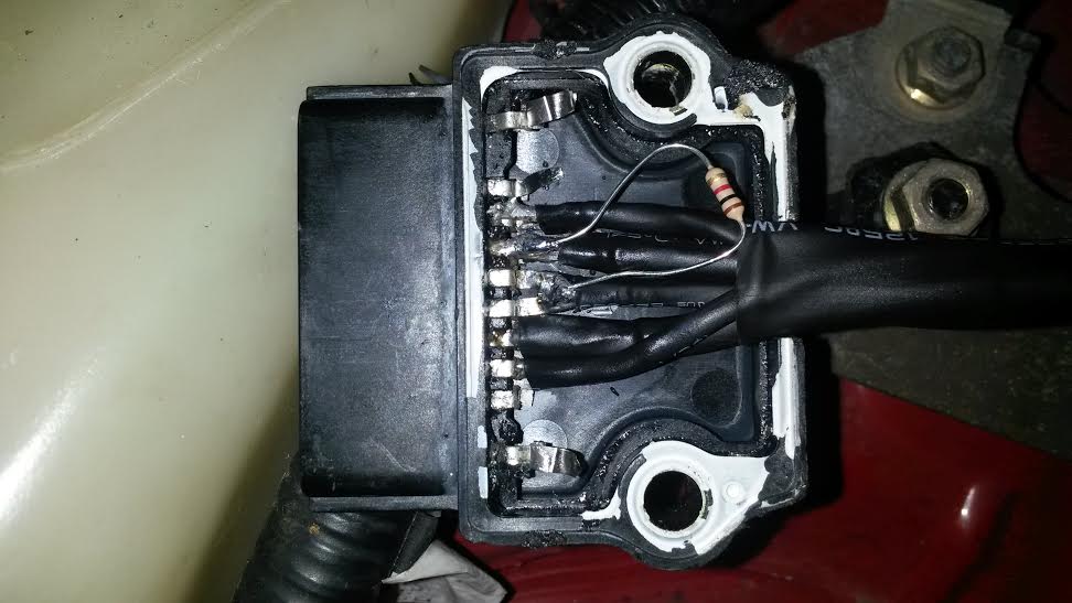
Would this work for less clutter? (Bad picture, but I would solder a resistor inside the igniter connecting Blue to Blue/yellow and then jump Blue yellow to black/white)
I have MSPNP1
What I dont understand is why that schematic shows the resistor bridging blue and yellow/blue, why not just place the resistor between the yellow/blue and white black instead?
I have MSPNP1
What I dont understand is why that schematic shows the resistor bridging blue and yellow/blue, why not just place the resistor between the yellow/blue and white black instead?
Reply
0
0
12-07-2014, 07:04 PM
#1729
I gutted the igniter, made a harness and soldered everything today, including the resistor. Not very pretty but it works! I used 12g wire for the 12v and ground signal and 18g wire for the rest.
Set my cranking dwell to 3.5ms and running dwell at 2.5ms and the car runs well. Thanks for all the help
Set my cranking dwell to 3.5ms and running dwell at 2.5ms and the car runs well. Thanks for all the help
Reply
0
0
12-07-2014, 10:36 PM
#1735
Retired Mech Design Engr
iTrader: (3)
Join Date: Jan 2013
Location: Seneca, SC
Posts: 5,009
Total Cats: 856
Inter web search shows JB Weld iron particles to be small enough that that bulk material is non-conductive. Still, I would prefer another, unfilled material. If you had stress sensitive components, then a more flexible urethane would be the normal potting choice, but epoxies are used, as well as electronic RTV, and, as Scott pointed out, hot melts.
I just didn't want you to do nothing, but it sounds like you had planned to pot.
I just didn't want you to do nothing, but it sounds like you had planned to pot.
Reply
0
0
 01-06-2015, 06:43 PM
#1737
Newb

Join Date: Apr 2009
Location: Austin, TX
Posts: 32
Total Cats: 3
Sorry if this is already in this thread but I've scanned over the 80+ pages of it and didn't see any mention relating.
Toyota COPs installed. Called DIY and they confirmed that my Megasquirt 1 has the capacitor built in. I did not install the resistor though but my tach works fine, sort-of.
Engine idles and cruises better than with OEM coils.
Problem is when it gets into boost above 6psi the engine shuts down and tach drops to null for a split second, like I turned the key off and back on real quick. Damn neck snapper. I can't get Tuner Studio to link up so no diag via software (whole other issue I'm working on).
Is this something that the resistor would help or yall have any other suggestions?
Thanks for any help fellas.
Reply
0
0
01-06-2015, 07:49 PM
#1738
Elite Member
iTrader: (2)

Join Date: Jun 2009
Location: Istanbul, Turkey
Posts: 3,214
Total Cats: 1,687
Sorry if this is already in this thread but I've scanned over the 80+ pages of it and didn't see any mention relating.
Toyota COPs installed. Called DIY and they confirmed that my Megasquirt 1 has the capacitor built in. I did not install the resistor though but my tach works fine, sort-of.
Engine idles and cruises better than with OEM coils.
Problem is when it gets into boost above 6psi the engine shuts down and tach drops to null for a split second, like I turned the key off and back on real quick. Damn neck snapper. I can't get Tuner Studio to link up so no diag via software (whole other issue I'm working on).
Is this something that the resistor would help or yall have any other suggestions?
Thanks for any help fellas.
Toyota COPs installed. Called DIY and they confirmed that my Megasquirt 1 has the capacitor built in. I did not install the resistor though but my tach works fine, sort-of.
Engine idles and cruises better than with OEM coils.
Problem is when it gets into boost above 6psi the engine shuts down and tach drops to null for a split second, like I turned the key off and back on real quick. Damn neck snapper. I can't get Tuner Studio to link up so no diag via software (whole other issue I'm working on).
Is this something that the resistor would help or yall have any other suggestions?
Thanks for any help fellas.
If so, revert back to wasted spark, your problems will go away.
Also, check charging voltage when the condition you describe happens. Does the voltage spike?
You might wanna log this event to verify.
Reply
0
0
01-07-2015, 01:07 AM
#1740
Newb

Join Date: Dec 2014
Location: Stevenage, UK
Posts: 9
Total Cats: 2
Sorry if this is already in this thread but I've scanned over the 80+ pages of it and didn't see any mention relating.
Toyota COPs installed. Called DIY and they confirmed that my Megasquirt 1 has the capacitor built in. I did not install the resistor though but my tach works fine, sort-of.
Engine idles and cruises better than with OEM coils.
Problem is when it gets into boost above 6psi the engine shuts down and tach drops to null for a split second, like I turned the key off and back on real quick. Damn neck snapper. I can't get Tuner Studio to link up so no diag via software (whole other issue I'm working on).
Is this something that the resistor would help or yall have any other suggestions?
Thanks for any help fellas.
Toyota COPs installed. Called DIY and they confirmed that my Megasquirt 1 has the capacitor built in. I did not install the resistor though but my tach works fine, sort-of.
Engine idles and cruises better than with OEM coils.
Problem is when it gets into boost above 6psi the engine shuts down and tach drops to null for a split second, like I turned the key off and back on real quick. Damn neck snapper. I can't get Tuner Studio to link up so no diag via software (whole other issue I'm working on).
Is this something that the resistor would help or yall have any other suggestions?
Thanks for any help fellas.
Worth checking. I since set my overboost to 170kPa with a 1kPa hysteresis so I can turn up the boost to 10psi gradually.
Cheers
Stot
Reply
0
0


