When you click on links to various merchants on this site and make a purchase, this can result in this site earning a commission. Affiliate programs and affiliations include, but are not limited to, the eBay Partner Network.
I wanted to get the oil return out of the way first.
AN fittings turned out to be cost prohibitive. (Turkish Lira took another swan dive against the Dollar.. Everything is expensive now with the 5.5 to 1 exchange rate)
Anyway.. Considered plumbing fittings, but they proved to be too bulky...
So, I took a deep breath and went at it anyway.
The hell with it, I said. I can get it patched up if I **** it up I said...
I sourced some 19 (or 21?) mm ID aluminum pipe, cut it to size and had them welded.
The hose is pretty flexible, is rated for elevated temps, and worked very well.
Both oil drain ports are within about 5 degrees of perpendicular.
I believe the ID is large enough to allow drainage...
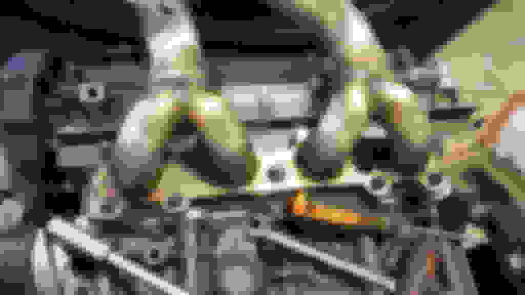
Since I had such a "cantilevered" setup, I did not want the weight of the turbo to yank the manifold studs out of the head, so I decided I should have an adjustable support system to take up the load.
I used M10 stainless threaded rods with LH and RH threaded adapters so I could adjust the compression.
Bolt holes in the block came in handy.
I took the pics during mock up.
Everything was cleaned up and painted before final assembly.
There is one drawback to installing all this stuff here: I'll never be able to install AC on this car.
Oh well.
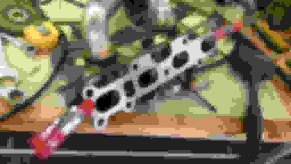
With the oil return all taken care of, it was time for oil feed lines.
Couple friends suggested I should route the lines around the back of the block, while some insisted they should be routed around the front.
They all had their reasons, of course.
I went with neither advice.
My oil lines are routed THROUGH the engine.
There is a "tunnel" right behind the timing belt rear cover, that's the tunnel I used.
All I had to do was drill a couple holes on my sandwich plate, tap them for the custom hoses I had a hydraulic shop make for me, and the rest was easy...
Same hoses, with the alternator in place.
The ends have banjo fittings and no restrictor.
Turns out these turbos have their built in restrictors in their respective oil inlet ports.
The chief engineer at BW confirmed this for me.
I used heat sleeves on every hose.
These are rated for 1500 C - or so I'm told.
They will be OK even if the manufacturer is exaggerating their rating by 50%.
Oh, I also routed the coolant line for the wastegate this way, too.
Going through the engine meant less clutter and using shorter hoses, but doing any kind of work under the intake manifold is a royal pain now.
Removing the alternator requires a whole new procedure, for example...
On a side note, I took a breather and replaced the rear deck carpeting @gesso brought for me all the way from California.
I really need to thank @Garman, @gesso and @sixshooter for their generosity, effort and all around camaraderie for this.
My rear deck carpet had a big hole in it (it's an age thing, things wear out in time) and it looks pretty spiffy now.
Did some surface rust removal and touch up paint while I was there...
To my horror, I discovered rust when I was removing the seats...
So I tore them apart and had all the metal media blasted and powdercoated.
I hate rust.
After media blasting and powdercoating...
Wait.. This is supposed to be a turbo build thread.
It has been 50 weeks since I started this project, and I have about 400+ pictures.
Sorting through all hat stuff takes a while. I have been sitting by he computer for several hours now, and I need to take a break...
Where was I?
Oh, heat management/insulation stuff...
I went nuts with it.
Made heat shields to cover all exposed surfaces
Covered all the hoses with fiberglass insulation and wrapped them in aluminum tape...
And fabbed a heat shield to protect master cylinders and stuff.
That shield has ceramic wool sandwiched between 1 mm aluminum sheet and that .30 mm textured stuff I really like using.
Unfortunately, I had to junk it. Did not work.
I made quite a few pieces like this one, they all ended up in the trash...
I would encapsulate the turbos and the manifold in an insulated heat shield.
There is an opening between the bottom of the radiator and the belly pan. It is roughly 25" x 2".
I would make a scoop there to collect the air rushing under the radiator, route it up and blow it into the heat shield encapsulating the turbos.
The hot air would then be diverted into the (now well insulated) trans tunnel and away from the car.
I decided covering up the heat source wold ultimately trap the heat, and went another direction...
I would cut the hood and make an active vent system!
Because this project was nowhere near complicated enough!
Because I was facing a credible risk of finishing the damn project before the year's end if I had stuck with my original plan!
Because I somehow found pleasure in making things more challenging for no apparent reason.
So I happily proceeded to design an active system.
I mean, what's wrong with just a fixed louver vent? Nooo, gotta be active. Jeez.
*****
That thing went through several design stages, several incarnations, several prototypes.
Many camels were smoked, many pots of tea was consumed in the process...
This was the first draft outline...
Next step would be a plaster mold of the hood, because it has curves.
A flat vent frame would distort the hood and ruin he car, so here we go...
(The entire hood as well as fenders are covered in thick, clear plastic film at this point.)
The mold gave me all the curves of the hood, and I proceeded to make a foam core prototype accordingly.
This frame would not distort the hood, that's for sure...
Turned out it was pretty impractical for an active setup, because the louvers would never be parallel to each other.
I mean, I had selected the shape and the location meticulously, pouring over pressure maps, forum posts, youtube videos and whathaveyou...
I have never heard of an optocoupler. Looks like the relay stuffs I've been using for arduino things. Maybe the chinese call it a relay so people like me know it's function.
How do you retighten the nuts inside Sputnik when they get loose? Or did you just tighten them a lot and loctite them?
I have never heard of an optocoupler. Looks like the relay stuffs I've been using for arduino things. Maybe the chinese call it a relay so people like me know it's function.
How do you retighten the nuts inside Sputnik when they get loose? Or did you just tighten them a lot and loctite them?
speaking from experience, loctite everything. The amount of hardware I have heard clunk off the undercarriage is embarrassing. For the first several weeks on the road I had to do a regular hardware inspection.
An optocoupler is a common electronic component used to isolate a signal from the input side to the output side. It allows you to control stuff without actually connecting to it electrically.
The more I read the more my mouth hung open. You spent too much time on that junkyard wars TV show. Your idea of normal construction is obviously skewed now, lol.
The more I read the more my mouth hung open. You spent too much time on that junkyard wars TV show. Your idea of normal construction is obviously skewed now, lol.
Kept trying different designs, attachment styles, shapes...
Chucked them all.
The only cost was time at this point, and I had time.
A couple friends - industrial designers by trade - volunteered to help me at that point.
We fired up some 3D programs and went at it full speed...
I had thought of a trick for this mold..
It would give me a raised area for the area to be cut on the hood, so I could "wrap" the frame around it to give it the proper curvatures.
This one worked.
Had another prototype cut out of cardboard.
I was planning on using 1.5 mm steel for the whole thing, so we had this cut from 1.5 mm cardboard.
The result was very satisfactory.
Please note the first slat, it sits at 90 degrees, while the others are at 45.
The reason behind this configuration is allowing the air to tumble over the upright slat, creating more of a low pressure zone over the rest of the louvers.
Science.
And they all close flat 3 minutes after I turn off the engine, once most of the heat rises away.
I have already built an override switch inside the center console.
That way, the louvers will not get stuck and bind if there is ice or snow on the hood. I can turn it off if I have to.
Feeling content with the result, it was time to fab the thing out of metal.
We decided it should be body color for a number of reasons: Attracting less attention was a factor, but aesthetics was the ultimate motivation in that decision.
With the air exit all figured out, I turned my attention to the air entering the engine bay.
I had installed a bunch of air diverters that channeled the incoming air through the radiator a few years ago, but they were ABS plastic, and had all turned pretty janky over time.
Some were cracked, a couple were broken all the way.
I thought nothing would be better than polycarbonate, and used a 2.3 mm sheet to replicate and replace them.
Also, there was a 2" opening between the radiator and the aluminum flat belly pan I had made about a year ago.
Now that I had discarded the idea of fabbing a scoop there, I decided I should make another diverter (fixed on the belly pan) to direct all the air to the radiator.
Took some measurements..
And bent it out of 1.5 mm aluminum.
A rubber mallet produces excellent results, and I can get the angles just right.
(I do not have room for a metal brake, and I don't bend stuff often, so this method works for me)
I used rivets to install it on the belly pan, works like a charm.
It can be (barely) seen below the radiator in this photo:
Last edited by Godless Commie; 12-19-2018 at 05:00 PM.
 12-18-2018, 05:20 PM


 2
2