My Turbo Miata Budget Build
 07-31-2016, 09:55 AM
#1
Junior Member
Thread Starter
iTrader: (1)

Join Date: Dec 2015
Location: Fairfax, VA
Posts: 143
Total Cats: 41
Well I think I’m officially far enough along into this project to start my own build thread. This was my first attempt at putting together and installing a turbo. I documented my process as much as I could to hopefully help others who are thinking of putting together a similar kit. I’m sure there are things I could have done differently/better so I’m open to suggestions as well, the project is never done.
The goal of this project was to build a budget DIY kit without cutting significant corners. This forum was a huge help in taking this on. The list of car details and primary components are as follows:
Car is a 94 R package with a swapped type 2 4.3 torsen and FM happy meal kit. Head was recently rebuilt by PO. Includes Exintake cam mod. Minor porting, slightly decked head. Prior to turbo install, the motor compression tested at around 205 psi across the board. (which seemed oddly high)
I purchased most of the items for this kit used, either through this forum, ebay, craigslist, etc. I’ve been collecting parts for around 2 months and tracking the costs closely. At this point, I should end up right around the $2k mark, tuning costs not included (I will update once complete). Once the car is up and running it will be getting tuned by Ken Hill from Oracle Tuning.
Update on Cost: Final build cost excluding tuning comes to $2,136. This includes everything from hose barbs, coolant hoses and copper nuts to the obvious things like full exhaust and Hydra ECU.
The build to this point has been relatively straight forward thanks in large part to many hours spent on here researching. The project has been pretty time consuming but I’ve enjoyed the process. From getting the car on jack stands to having the turbo installed and drivable on hydra took me about 3 weeks.
Pictures are where it’s at so here’s a timeline of events.
The goal of this project was to build a budget DIY kit without cutting significant corners. This forum was a huge help in taking this on. The list of car details and primary components are as follows:
Car is a 94 R package with a swapped type 2 4.3 torsen and FM happy meal kit. Head was recently rebuilt by PO. Includes Exintake cam mod. Minor porting, slightly decked head. Prior to turbo install, the motor compression tested at around 205 psi across the board. (which seemed oddly high)
- SR20 T25 and rebuild kit from gpopshop
- 3AN Turbo oil line.
- TacoTaco t25 cast manifold.
- UNI foam filter
- Nissan 300zx Inconel studs/copper locking flange nuts
- RX8 Yellow injectors
- Rev9 Intercooler 20x6.5x2.5 core
- Generic 2.5” I/C piping/couplers
- Knockoff Type S BOV (we will see)
- First Gen FM Downpipe 2.25” (Yes I know this is not ideal,)
- Eastern 200 cell metal cat (2.5”)
- Magnaflow 5x11x22 Muffler (2.5”)
- Custom Exhaust from local shop (2.5 mandrel bends.)
- Hydra 2.6
I purchased most of the items for this kit used, either through this forum, ebay, craigslist, etc. I’ve been collecting parts for around 2 months and tracking the costs closely. At this point, I should end up right around the $2k mark, tuning costs not included (I will update once complete). Once the car is up and running it will be getting tuned by Ken Hill from Oracle Tuning.
Update on Cost: Final build cost excluding tuning comes to $2,136. This includes everything from hose barbs, coolant hoses and copper nuts to the obvious things like full exhaust and Hydra ECU.
The build to this point has been relatively straight forward thanks in large part to many hours spent on here researching. The project has been pretty time consuming but I’ve enjoyed the process. From getting the car on jack stands to having the turbo installed and drivable on hydra took me about 3 weeks.
Pictures are where it’s at so here’s a timeline of events.
Last edited by kmo25; 08-11-2016 at 08:31 AM.

Reply
 1
1

1
07-31-2016, 10:24 AM
#2
Junior Member
Thread Starter
iTrader: (1)
Join Date: Dec 2015
Location: Fairfax, VA
Posts: 143
Total Cats: 41
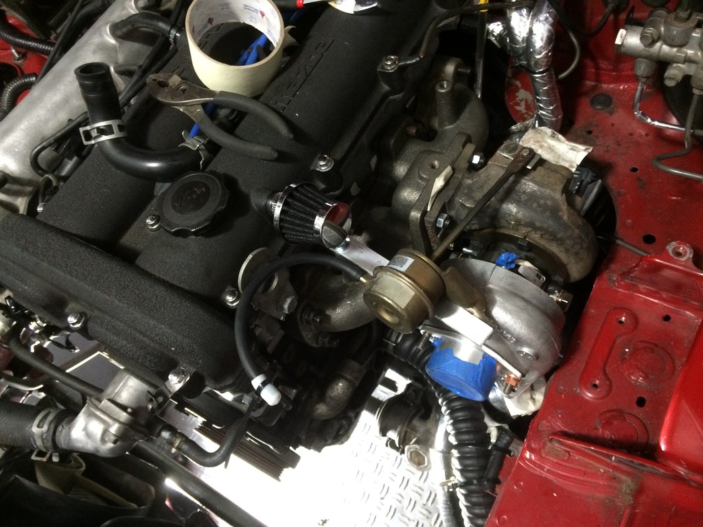
Turbo Install
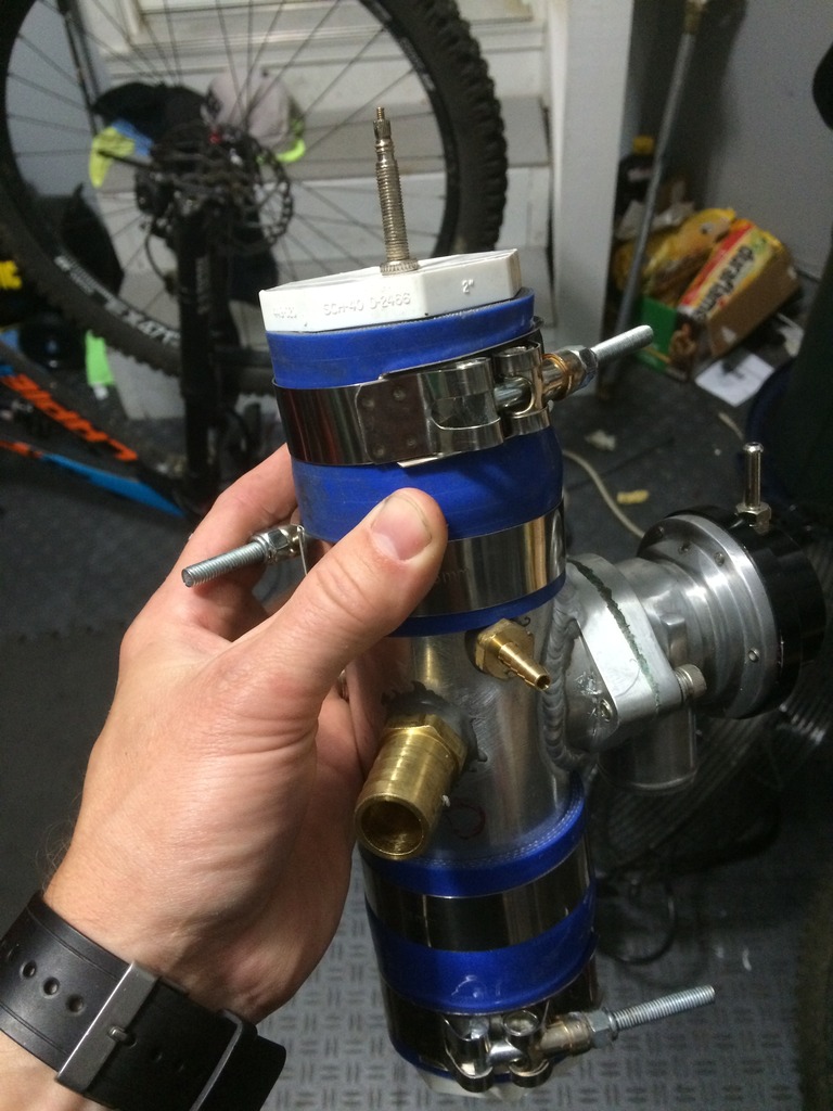
Turbo (Garrett T25G) purchased from Ebay. Turbo was in rough shape, no significant shaft play, just covered in oil and rusty as hell. Dirt and debris was also all over the turbine and compressor wheels so I figured my best bet would be to rebuild. The turbine nuts were a bitch. Not so much for being frozen but it was very hard to get a wrench to two of the bolts. Ended up needing to dremel one of my wrenches to fit. Once completely dissembled, I soaked the CHRA and Turbine housing in stuff called Evapo-Rust. Its PH neutral and is pretty amazing. I also used it on the top section of the FM downpipe, which had been rusting away for probably over 20 years. It took all the rust off. Also used it on most of the small rusty things I removed (bolts, etc). Once everything was clean I went about reassembling. The only things that gave me trouble here were getting the new small wavy clips back in and putting in the split washer thing on the backside of the turbo housing.
Little trick I got from the guys at Gpop: when reinstalling the little wavy clips the bearings rest on, just get the clip into the shaft housing straight and push it down with the old bearing. They popped right into place doing it this way.
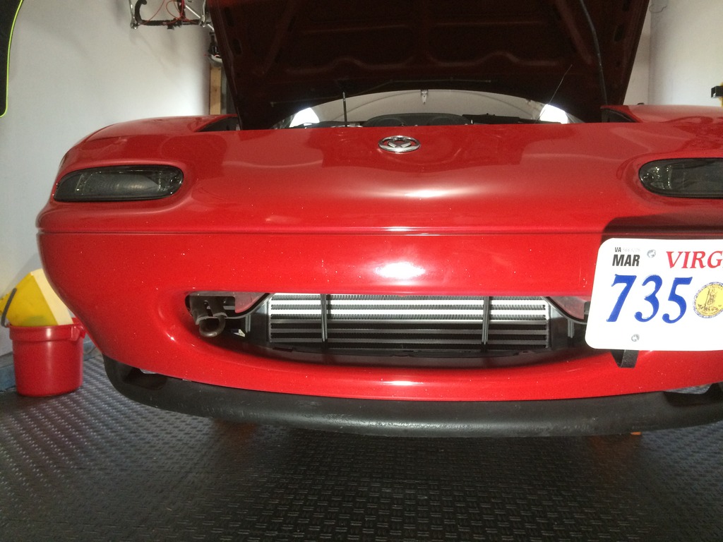
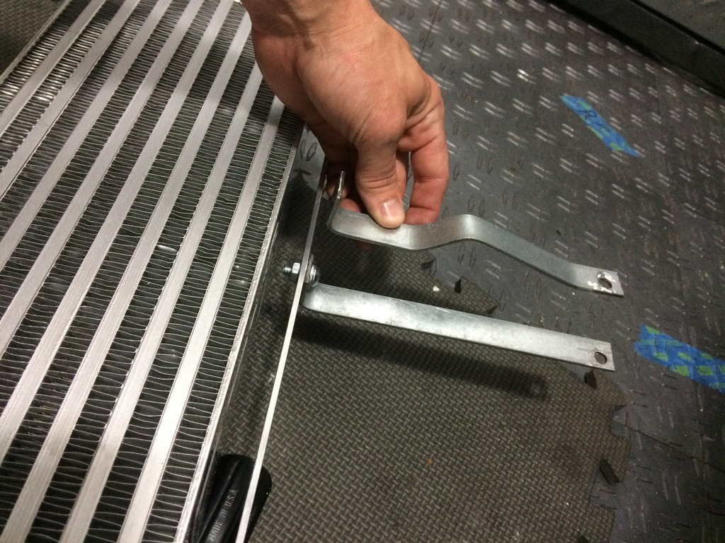
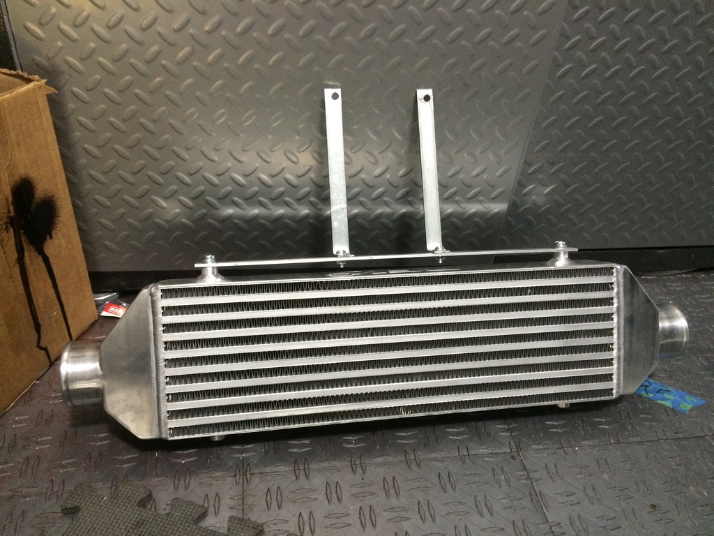
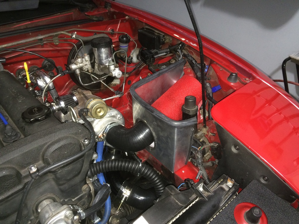
Skip ahead a few weeks, with most of the parts on hand I got myself a fresh state inspection, drove it home into the garage, and put it on stands. Figured I would remove the front bumper to make life a little easier. Intercooler fits perfectly into the front grill area. I created brackets like FM does and mounted them to the hood latch (like FM does). The only thing I needed to cut was the sides of the radiator shroud to allow the IC piping into the sides. The intercooler is made by Rev9 which I think is the same as Godspeed. It was $65 on amazon. Looks prertty good.
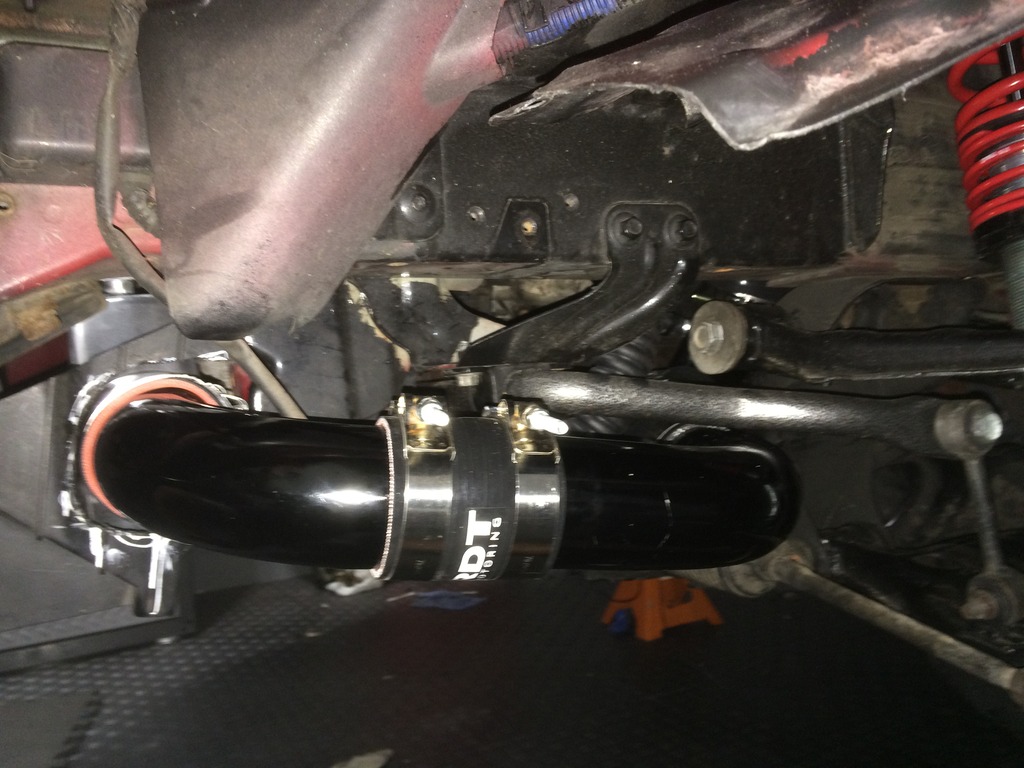
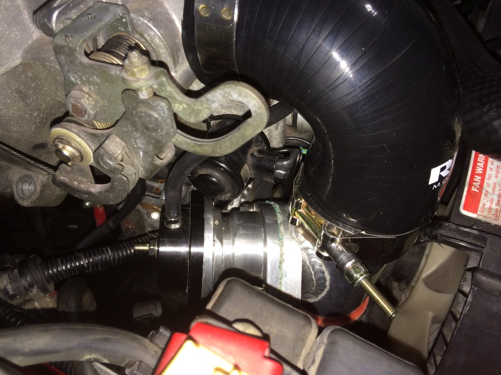
Then I set about test fitting IC piping orientation. Life probably would have been easier if I clocked the turbo so that the outlet pointed straight up toward the hood and then did two 90�s down. This would have also allowed me to not have to mess with creating a new wastegate bracket. Figured pointing it down eliminated some unnecessary bends, shorter pipe length, and just looks cleaner. To make this work I needed to pick up a flex coolant hose from autozone. It was $12 and either 22 or 23� (Should have looked for 20� in hindsight.
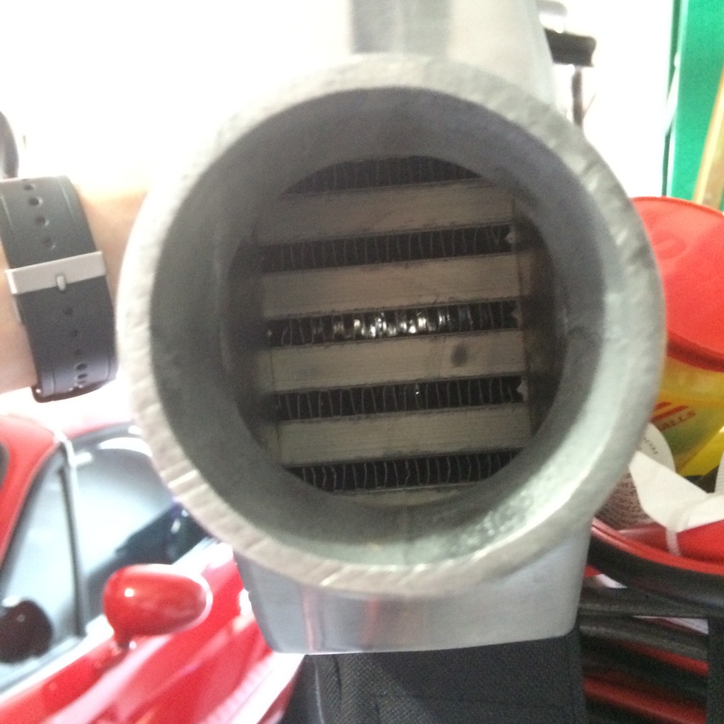
Later drilled and tapped the cold side of the IC for the IAT. Used a HF tap set which has worked quite well throughout this project. It was $15 for �, 3/8 and � NPT.
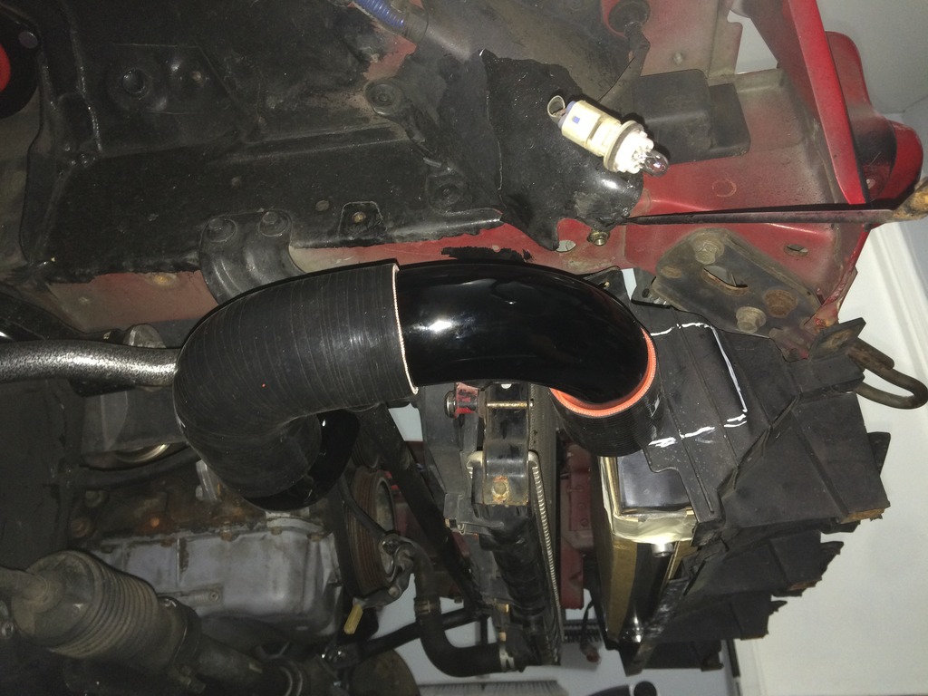
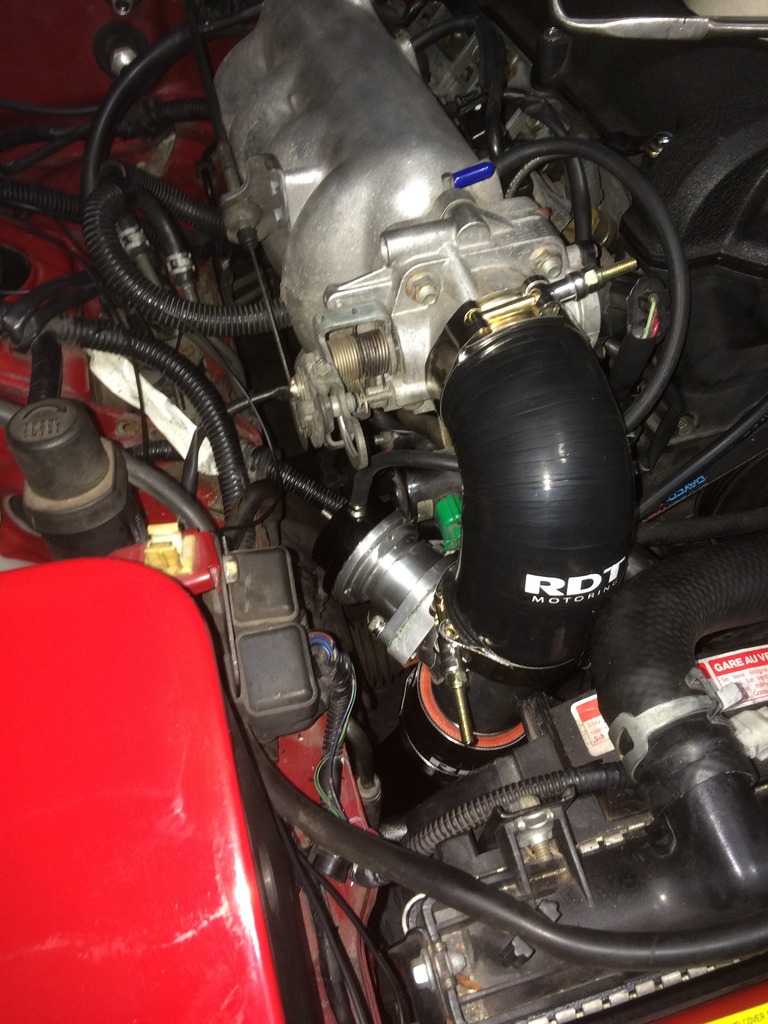
Then did the cold side pipe routing. Ended up needing to trim the silicon elbow down a bit as well as one of the radiator fan supports. I drilled and taped the BOV section of pipe to run the waste gate signal line and IACV. I used JBweld on these fittings. I saw a lot of mixed reviews on this method here, but I have used JBweld with great success in the past (used it to patch a small punch hole on the side of my race bikes radiator and it held up for over 2 years of tracking/racing). I found JBweld works great when you sand around the area you are applying as well. Like paint, I imagine it works better when it has something to grab. (forgot to take my own advice later in this thread)
Turbo (Garrett T25G) purchased from Ebay. Turbo was in rough shape, no significant shaft play, just covered in oil and rusty as hell. Dirt and debris was also all over the turbine and compressor wheels so I figured my best bet would be to rebuild. The turbine nuts were a bitch. Not so much for being frozen but it was very hard to get a wrench to two of the bolts. Ended up needing to dremel one of my wrenches to fit. Once completely dissembled, I soaked the CHRA and Turbine housing in stuff called Evapo-Rust. Its PH neutral and is pretty amazing. I also used it on the top section of the FM downpipe, which had been rusting away for probably over 20 years. It took all the rust off. Also used it on most of the small rusty things I removed (bolts, etc). Once everything was clean I went about reassembling. The only things that gave me trouble here were getting the new small wavy clips back in and putting in the split washer thing on the backside of the turbo housing.
Little trick I got from the guys at Gpop: when reinstalling the little wavy clips the bearings rest on, just get the clip into the shaft housing straight and push it down with the old bearing. They popped right into place doing it this way.
Skip ahead a few weeks, with most of the parts on hand I got myself a fresh state inspection, drove it home into the garage, and put it on stands. Figured I would remove the front bumper to make life a little easier. Intercooler fits perfectly into the front grill area. I created brackets like FM does and mounted them to the hood latch (like FM does). The only thing I needed to cut was the sides of the radiator shroud to allow the IC piping into the sides. The intercooler is made by Rev9 which I think is the same as Godspeed. It was $65 on amazon. Looks prertty good.


Then I set about test fitting IC piping orientation. Life probably would have been easier if I clocked the turbo so that the outlet pointed straight up toward the hood and then did two 90�s down. This would have also allowed me to not have to mess with creating a new wastegate bracket. Figured pointing it down eliminated some unnecessary bends, shorter pipe length, and just looks cleaner. To make this work I needed to pick up a flex coolant hose from autozone. It was $12 and either 22 or 23� (Should have looked for 20� in hindsight.


Later drilled and tapped the cold side of the IC for the IAT. Used a HF tap set which has worked quite well throughout this project. It was $15 for �, 3/8 and � NPT.
Then did the cold side pipe routing. Ended up needing to trim the silicon elbow down a bit as well as one of the radiator fan supports. I drilled and taped the BOV section of pipe to run the waste gate signal line and IACV. I used JBweld on these fittings. I saw a lot of mixed reviews on this method here, but I have used JBweld with great success in the past (used it to patch a small punch hole on the side of my race bikes radiator and it held up for over 2 years of tracking/racing). I found JBweld works great when you sand around the area you are applying as well. Like paint, I imagine it works better when it has something to grab. (forgot to take my own advice later in this thread)


Reply
1
1
07-31-2016, 10:42 AM
#3
Junior Member
Thread Starter
iTrader: (1)
Join Date: Dec 2015
Location: Fairfax, VA
Posts: 143
Total Cats: 41
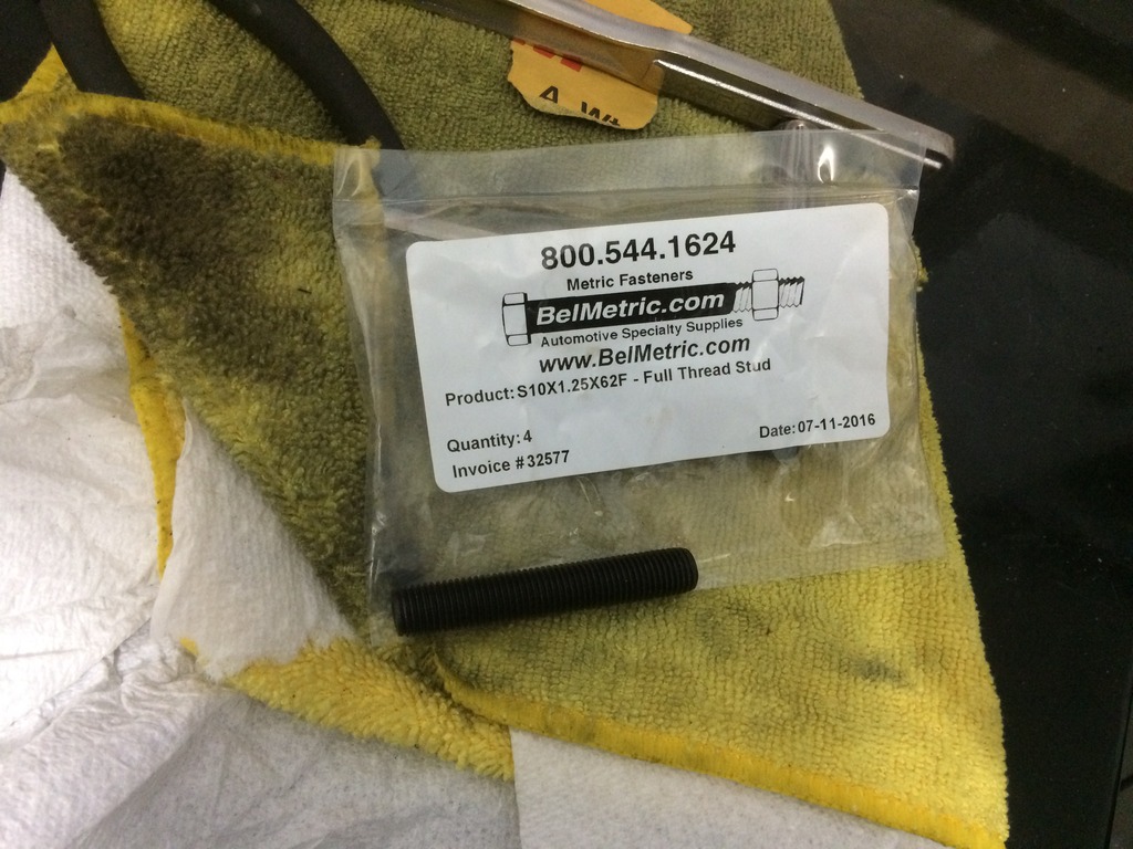
Mounted the manifold to the block. Pretty straight forward. Ended up getting m10x1.25 x62mm fully threaded studs from bel metric. These were suggested by a member on another thread but I don’t recall if anyone showed them installed. Well here they are, the work perfectly for this manifold and ended up being around $17 shipped. Dip stick tube needed to be bent backward as well as the water line. Also had to cut the water line bracket slightly to work with the Taco Manifold.
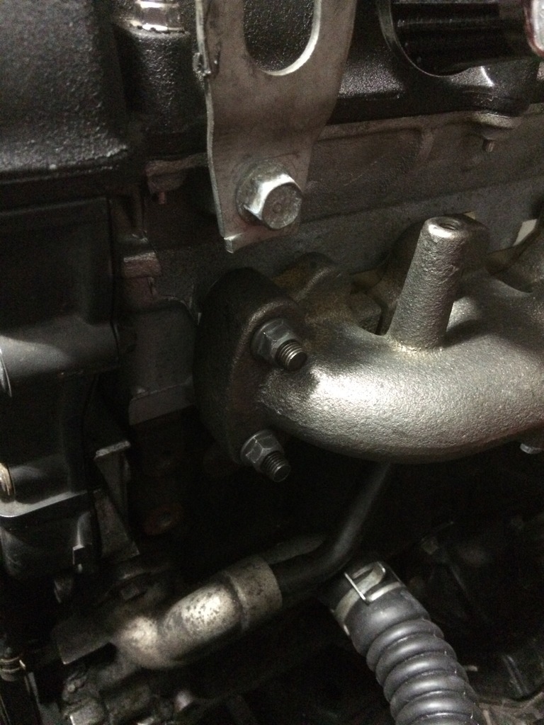
With this setup the turbo seems to have good clearance from the shelf, however, the turbo must be mounted to the manifold after the manifold is installed. You cannot install the manifold and turbo as one unit, especially due to the longer studs. Even so I didn’t really have any trouble tightening the nuts. It also helps that these copper nuts have a 10mm head which makes getting a wrench in there a lot easier.
Turbo mounted. Simple 2.25 to 2.5 90 degree bend and a small piece of cut 2.5 IC pipe to the UNI filter. Fits perfectly.
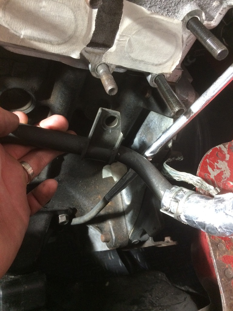
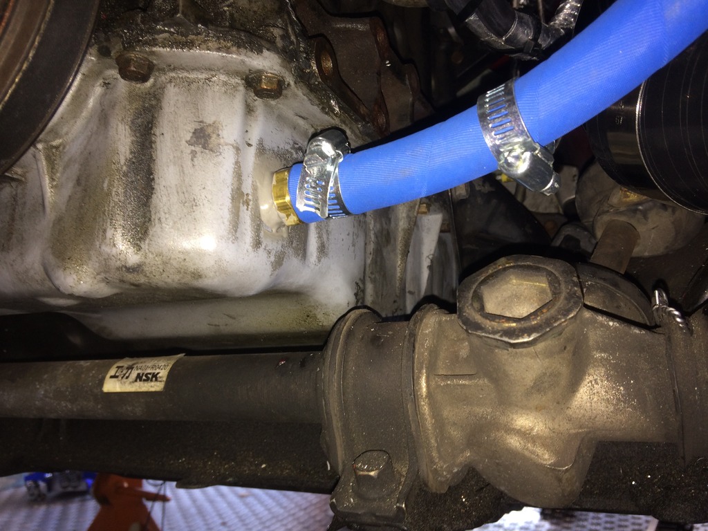
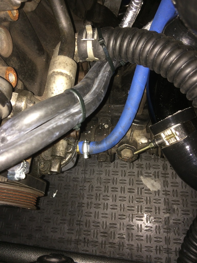
Mounted the DP to the turbo. The small first gen 2.25” pipe clears the rear shelf with plenty of space. However, the bottom two bolts are a pain in the *** to get to. I actually couldn’t get one of them in because there wasn’t enough space for the head of the bolt to actually spin. I ended up needing to use 2 studs on the bottom mounting points. I used three of the 300ZX Iconel bolts for the remainder. The bolts were too long though and bottomed out before being tight so I added a crush washer and washer to give them some space. Ran the Oil line. No issues here, just played around with the routing. Kept the connection points to a minimum. One insert into block (m10 by 1.5 I believe?) to 3AN, straight 3AN to 90 degree 3AN hose (36”) and one inverted flare fitting in turbo to 3AN. Also covered the oil line with extra coolant hose in areas of contact. Wrapper the heater lines, brake hard line and brake reservoir with heat wrap. Then wrapped the coolant lines with heat wrap and hooked them up. I assumed it didn’t matter if they were run under the lower coolant hose as the system flowed via a pump but I’m not entirely sure. May need to run them over the hose. I could see this being more an issue once the car is shut down.


With this setup the turbo seems to have good clearance from the shelf, however, the turbo must be mounted to the manifold after the manifold is installed. You cannot install the manifold and turbo as one unit, especially due to the longer studs. Even so I didn’t really have any trouble tightening the nuts. It also helps that these copper nuts have a 10mm head which makes getting a wrench in there a lot easier.
Turbo mounted. Simple 2.25 to 2.5 90 degree bend and a small piece of cut 2.5 IC pipe to the UNI filter. Fits perfectly.

Mounted the DP to the turbo. The small first gen 2.25” pipe clears the rear shelf with plenty of space. However, the bottom two bolts are a pain in the *** to get to. I actually couldn’t get one of them in because there wasn’t enough space for the head of the bolt to actually spin. I ended up needing to use 2 studs on the bottom mounting points. I used three of the 300ZX Iconel bolts for the remainder. The bolts were too long though and bottomed out before being tight so I added a crush washer and washer to give them some space. Ran the Oil line. No issues here, just played around with the routing. Kept the connection points to a minimum. One insert into block (m10 by 1.5 I believe?) to 3AN, straight 3AN to 90 degree 3AN hose (36”) and one inverted flare fitting in turbo to 3AN. Also covered the oil line with extra coolant hose in areas of contact. Wrapper the heater lines, brake hard line and brake reservoir with heat wrap. Then wrapped the coolant lines with heat wrap and hooked them up. I assumed it didn’t matter if they were run under the lower coolant hose as the system flowed via a pump but I’m not entirely sure. May need to run them over the hose. I could see this being more an issue once the car is shut down.

Reply
1
1
07-31-2016, 11:01 AM
#4
Junior Member
Thread Starter
iTrader: (1)
Join Date: Dec 2015
Location: Fairfax, VA
Posts: 143
Total Cats: 41
Then it was time to drill the pan. Like most say, this process isn’t hard, it’s just nerve wrecking. Followed numerous write ups on this. The biggest pain was that I had to rent a � in drive drill as all I could source was a 3/8 drill. Drill bit was a 23/32. Used a ton of bearing grease on the bit and taped it so it would not punch through. Hole drilled fine and the tape caught the bit easily Used bent Q tips to try to fish out shavings, found a decent amount of shavings with the Qtip at the bottom of the pan under the hole. Also found that some of the grease seemed to have flung off inside as directly
For the tap I actually used the HF � NPT tap. Was a little nervous but all the taps held up very well for me through the project. No damage to the tap threats and created nice clean threads in the pan. Installed � NPT to 5/8 barb with JB weld, put on oil return line, flushed with about � gallon of mineral spirits. I think I read a post where people talk about flushing numerous times but looks like FM says you only need a quart. What I did was probably overkill. I let it air out with the drain plug off for about 25 minutes, then filled with new oil. Dip stick still had a bit of a mineral spirits smell so I ended up changing the oil again after running the car initially.
Here is where I messed up with JBWeld I have used JB weld numerous times and know the importance of prep but somehow I’m pretty sure I completely forget to prep. I think I just wiped the grease off the pan because the JBweld never really cured fully and I could scrap it off with a pick several days later. There should still be some in the threads of the fitting and its NPT so it should be alright without it on the outside but I will have to keep an eye on it to see if it leaks. If it does, hopefully I will be able to just back it out and redo the JB weld properly with good cleaning.
I also ran into some issues running the return hose. When installing the oil return tube, the IC piping was getting in the way to the point where to get around it there would be a pretty long flat spot, or the line would have a slight kink in it. I also don’t like how its resting on the IC piping and looks cluttered. However at this point I have not changed it. Here is where the alternate turbo routing would have proven easier.
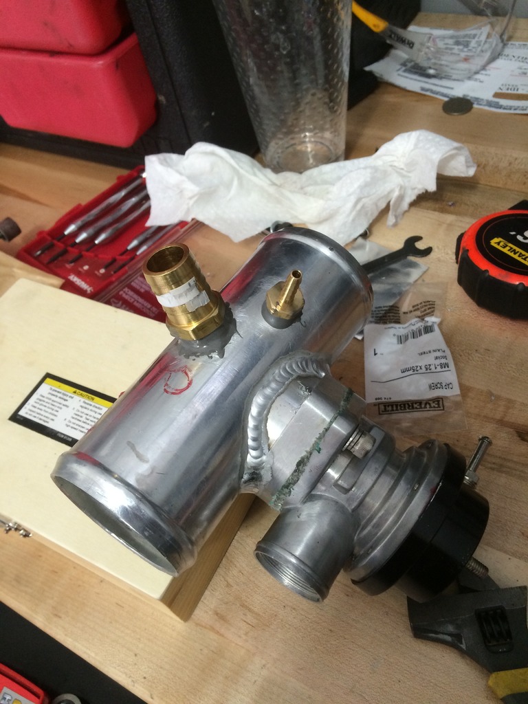
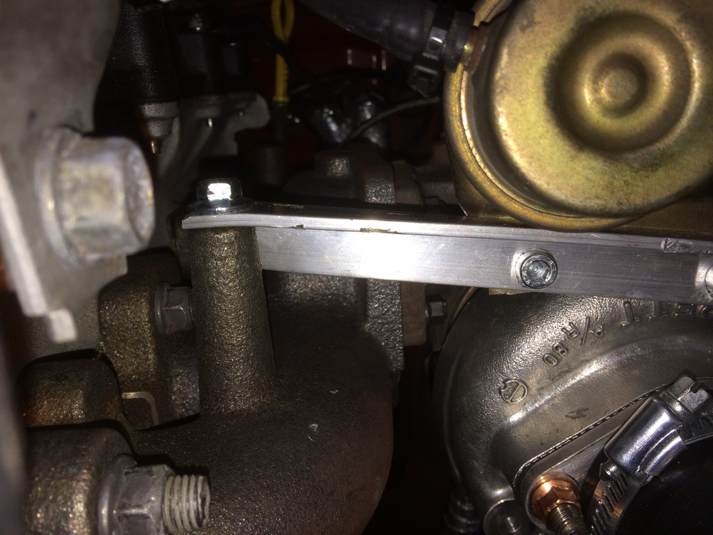
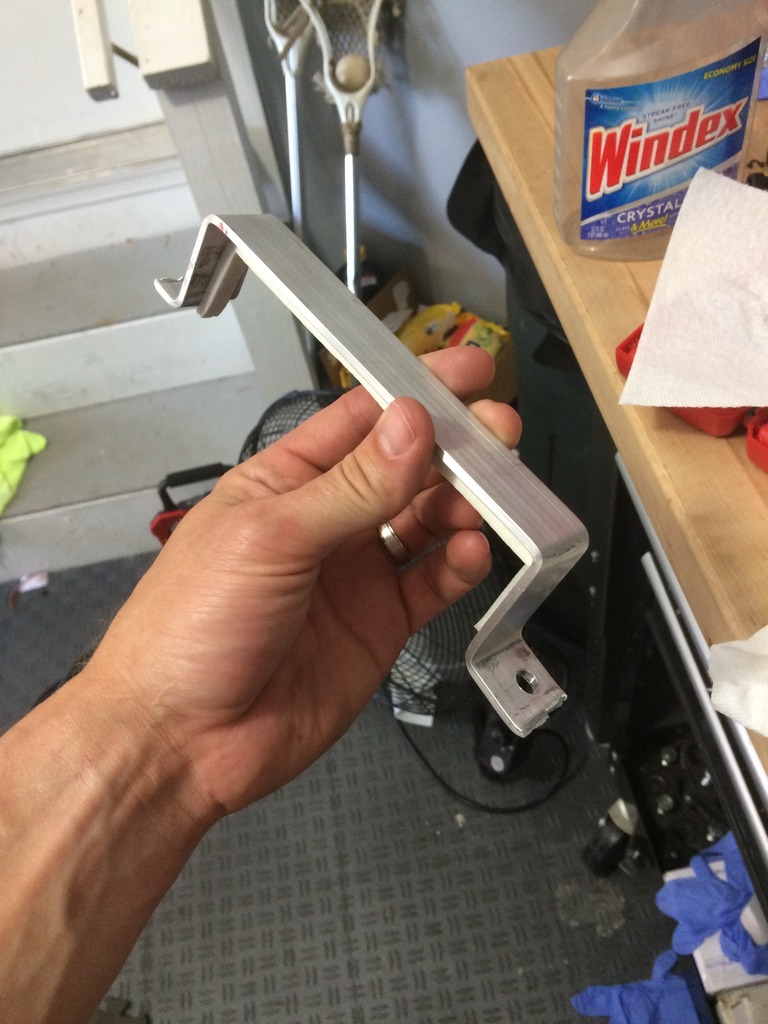
Then I made a bracket for the wastegate. Looks like the heat shield mount point on the Taco Manifold can come in handy for something. My first attempt was to bend/cut a piece of aluminum and attach it to the inlet stud. Unfortunately the aluminum wasn’t strong enough and would flex a lot when I tested the wastegate. For this mounting I used an L piece of aluminum for added strength but still easy enough to bend slightly for mounting purposes. This set up still has a very minor level of flex (a few mm) but I don’t think it will be an issue. Although it still looks a bit ghetto I think it looks a lot cleaner than the first attempt.
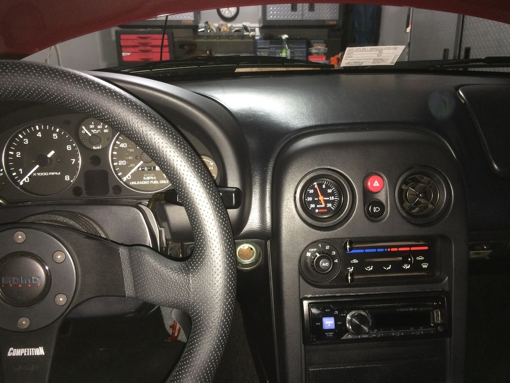
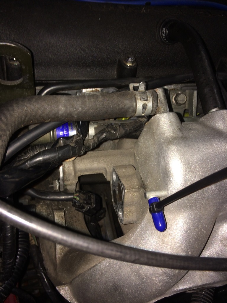
In preparation for the Hydra I ran a vacuum hose into the cabin. I also installed a boost gauge into the eyeball vent. The gauge is just a cheap Bosch mechanical gauge, but it does the job and actually looks pretty nice too. Seemed to work with vacuum when I drove it a few times still NA. Read a perfect 0 at WOT.
Before installing the BOV I figure I would run a little test to see if it would hold pressure. Looks ridiculous and I couldn’t really tell if it worked. It would hold some pressure for a second then I could hear it escaping from the BOV. This was around 20psi of pressure though. The plastic pieces didn’t fit well and were leaking too so I eventually said screw it.
Once I had everything set up I pulled the main relay and cranked the motor a few times. This was to remove fuel pressure and prime the turbo. Then I installed the RX8 injectors. This was probably one of the easiest parts of this project. I forgot to use oil on the o rings, but they slid right in. After I hooked it all back up I jumped the F/P to GRD in the diag box to prime the fuel rail. No leaks. Oh wait, there was one easier project…spark plugs. BKR7E Gapped to .034. May need to lower that a bit. Also put in a new fuel filter.
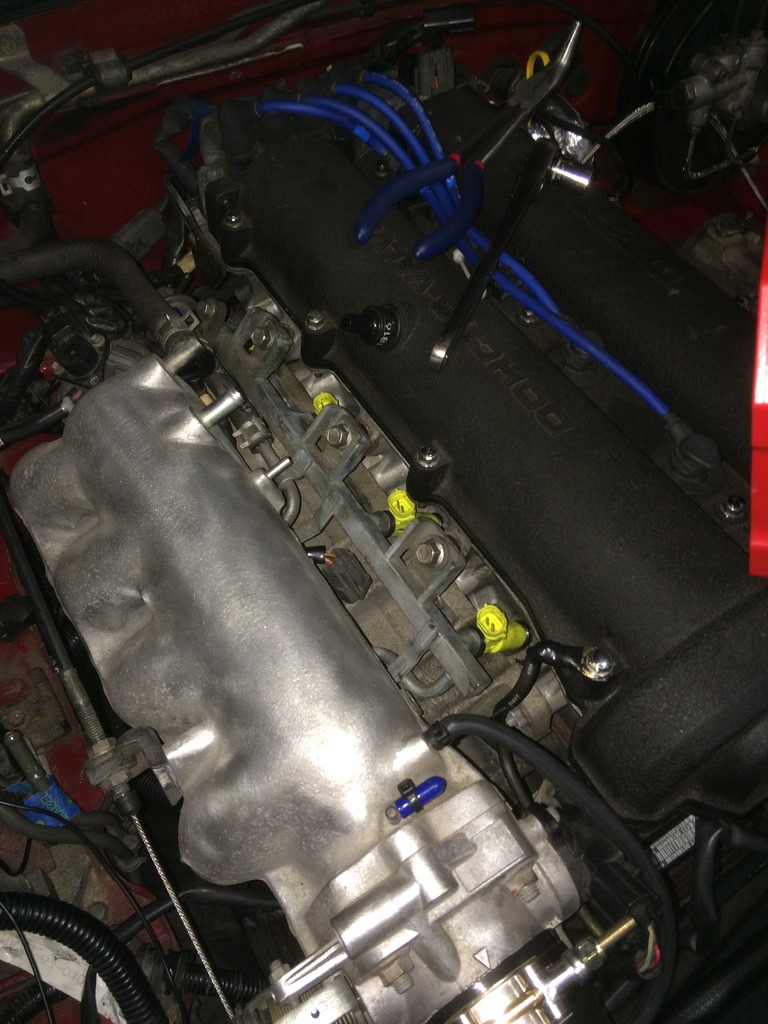
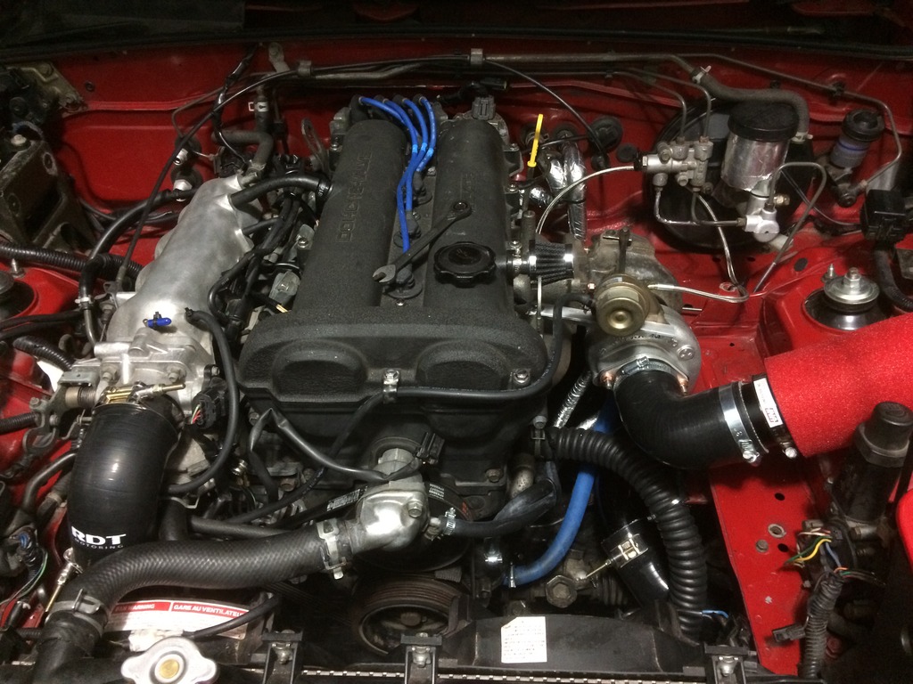
Installed the EGR block off plate from FM to clean up the intake side of the engine bay a bit. I do enjoy the minimalist look of the engine bay, but with temps in the 90’s the past few weeks in VA I’m sure I’ll wish I had AC (Previous owner appears to have taken it out) Also made a little plate to block off the EGR pipe connector. This is not needed as the FM plate ultimately blocks this path anyway, I just don’t like open cavities in the engine bay.
For the tap I actually used the HF � NPT tap. Was a little nervous but all the taps held up very well for me through the project. No damage to the tap threats and created nice clean threads in the pan. Installed � NPT to 5/8 barb with JB weld, put on oil return line, flushed with about � gallon of mineral spirits. I think I read a post where people talk about flushing numerous times but looks like FM says you only need a quart. What I did was probably overkill. I let it air out with the drain plug off for about 25 minutes, then filled with new oil. Dip stick still had a bit of a mineral spirits smell so I ended up changing the oil again after running the car initially.
Here is where I messed up with JBWeld I have used JB weld numerous times and know the importance of prep but somehow I’m pretty sure I completely forget to prep. I think I just wiped the grease off the pan because the JBweld never really cured fully and I could scrap it off with a pick several days later. There should still be some in the threads of the fitting and its NPT so it should be alright without it on the outside but I will have to keep an eye on it to see if it leaks. If it does, hopefully I will be able to just back it out and redo the JB weld properly with good cleaning.
I also ran into some issues running the return hose. When installing the oil return tube, the IC piping was getting in the way to the point where to get around it there would be a pretty long flat spot, or the line would have a slight kink in it. I also don’t like how its resting on the IC piping and looks cluttered. However at this point I have not changed it. Here is where the alternate turbo routing would have proven easier.


Then I made a bracket for the wastegate. Looks like the heat shield mount point on the Taco Manifold can come in handy for something. My first attempt was to bend/cut a piece of aluminum and attach it to the inlet stud. Unfortunately the aluminum wasn’t strong enough and would flex a lot when I tested the wastegate. For this mounting I used an L piece of aluminum for added strength but still easy enough to bend slightly for mounting purposes. This set up still has a very minor level of flex (a few mm) but I don’t think it will be an issue. Although it still looks a bit ghetto I think it looks a lot cleaner than the first attempt.

In preparation for the Hydra I ran a vacuum hose into the cabin. I also installed a boost gauge into the eyeball vent. The gauge is just a cheap Bosch mechanical gauge, but it does the job and actually looks pretty nice too. Seemed to work with vacuum when I drove it a few times still NA. Read a perfect 0 at WOT.

Before installing the BOV I figure I would run a little test to see if it would hold pressure. Looks ridiculous and I couldn’t really tell if it worked. It would hold some pressure for a second then I could hear it escaping from the BOV. This was around 20psi of pressure though. The plastic pieces didn’t fit well and were leaking too so I eventually said screw it.

Once I had everything set up I pulled the main relay and cranked the motor a few times. This was to remove fuel pressure and prime the turbo. Then I installed the RX8 injectors. This was probably one of the easiest parts of this project. I forgot to use oil on the o rings, but they slid right in. After I hooked it all back up I jumped the F/P to GRD in the diag box to prime the fuel rail. No leaks. Oh wait, there was one easier project…spark plugs. BKR7E Gapped to .034. May need to lower that a bit. Also put in a new fuel filter.

Installed the EGR block off plate from FM to clean up the intake side of the engine bay a bit. I do enjoy the minimalist look of the engine bay, but with temps in the 90’s the past few weeks in VA I’m sure I’ll wish I had AC (Previous owner appears to have taken it out) Also made a little plate to block off the EGR pipe connector. This is not needed as the FM plate ultimately blocks this path anyway, I just don’t like open cavities in the engine bay.

Reply
1
1
07-31-2016, 11:18 AM
#5
Junior Member
Thread Starter
iTrader: (1)
Join Date: Dec 2015
Location: Fairfax, VA
Posts: 143
Total Cats: 41
Installing Hydra
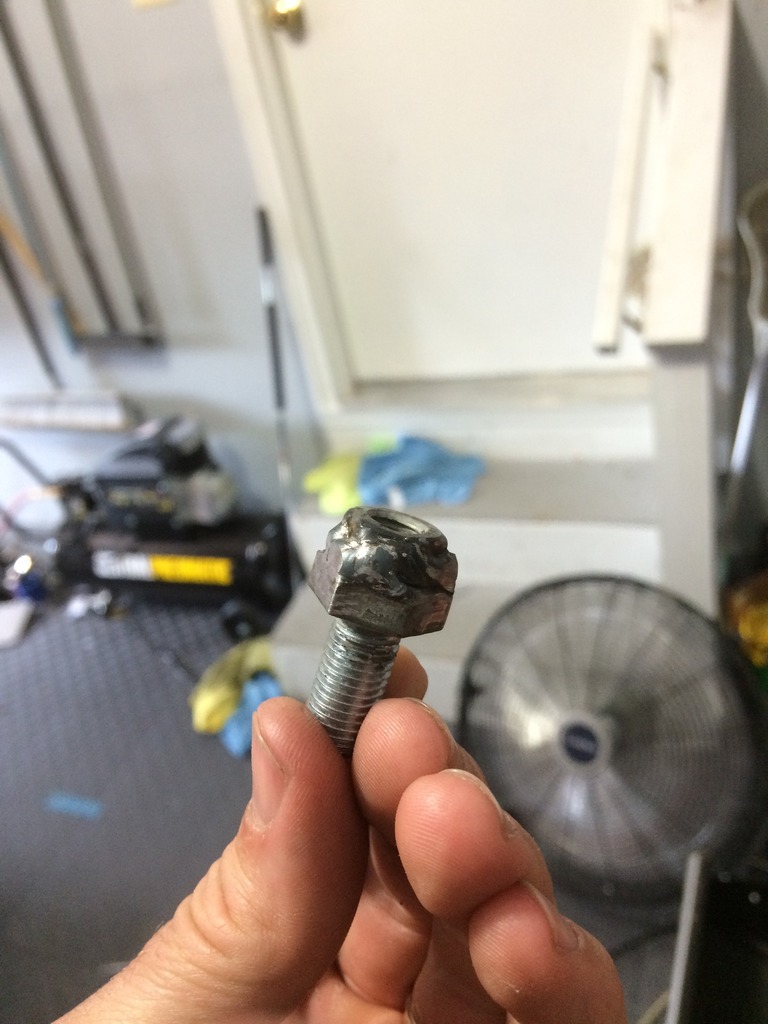
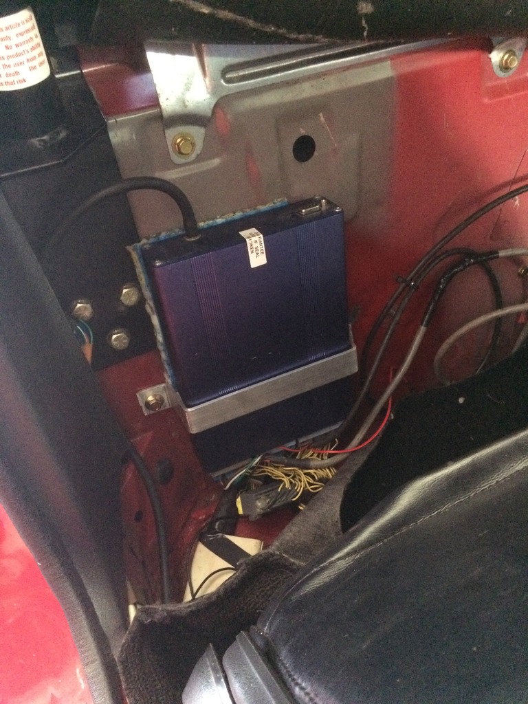
The person I bought the Hydra from did not include the knock sensor. I picked a knock sensor up from eBay for $8. The next problem was how to create an adapter the get the knock sensor which accepts up to about an m8 bolt to thread into an m10. At first I thought I could possibly bore the knock sensor to accept the larger bolt. No dice. The easiest solution for me was to take the m10x1.25 bolt and have an exhaust shop weld a m8x1.25 nut (you could use whatever thread you want) on top of the head of the bolt. Then I took it home and grinded the welds down so my socket could get around the m10 bolt head. Easy as that, will still try the $8 knock sensor with this setup (might have damaged it with the drilling) but can always buy another one if need be.
Getting the Hydra mounted also took longer than I was expecting. Person I bought the hydra from just cut the 5 wires for the WBO2 sensor, likely to make uninstall easier. So these had to be reconnected. I twisted, soldered, and shrink wrapped them, then wrapped the bundle in electrical tape. They also cut the Coax wire for the knock sensor so the wires needed to be separated and have terminal connectors added. Also had to run a wire from the AIT sensor in the intercooler directly to the Hydra as I don�t have power steering and could not tap into that wire (unless it was just sitting somewhere in the engine bay unused and I didn�t know it). Pinned that into the Hydra at BD09. I ended up running the WBO2 and the knock sensor wires through the shifter opening.
Made a bracket to hold the Hydra and attached it using one of the factory studs. The serial to USB cable stop the carpet from laying flush. The ECU also sticks out a bit further than the OEM unit so it�s not perfectly flush but it does the job. Passenger seat goes as far back as it did before.
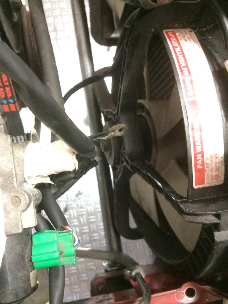
As I did not have a wideband bung, I needed to disable closed loop and get it to an exhaust shop but before I did that I had to get the car running/idling. I loaded the basemap Ken sent me, made sure I was getting good readings from my sensors and gave it a shot. No luck. Car would crank but not fire. Ken gave me a call and we worked through the issues for over an hour. He was a huge help. The clearance for the IC piping to the throttle body on the 94-95 is pretty crappy between the IACV, IACV plug (green plug) and Radiator fan shroud. The IACV plug wires had gotten smashed and the insulation had been cut. It seemed to be creating a short as there was a loud electrical humming coming from the area so we pulled the green plug.
We went through the normal checks to verify we were getting fuel, air, spark.
Tried to start the car again. Nothing. Then we added more fuel. Still nothing. Checked plugs, they were dry. Then we added even more fuel. Nothing. Then we checked for spark. Here is where it got interesting. I pulled the plug connected it to the coil and placed the spark plug lead, or whatever its called, on the intake manifold. My wife cranked the car and it actually started�..with the plug out. Scared the crap out of me. So we had fuel air and spark. Put the plug back in and tried again. Nothing. Disconnected just the coil and tried again. Nothing. Then I thought maybe it had to do with a grounding issue. As it seemed to fire when I was grounding the plug on the intake manifold. I also thought about it because for whatever reason my car was missing the normal ECU ground point. I had ended up grounding to a valve cover bolt, which Ken said wasn�t the best. I was using a 8 gauge wire to extend the length of the ecu ground. Then we attached it to one of the throttle body bolts. Tried it again. Car fired, but immediately would die. Tried again and gave it some gas to try to hold revs to see if the hydra was actually running the car. I held it at about 2k RPM and it seemed good, let off gas and it died. We called it a night
Ken sent me an idea for a work around for the IACV plug which was to essentially cut off the plug and just add to small terminal connected to plug directly in, eliminating the big green plug.
Hooked everything back up and gave it another shot. Car fired on the second crank and went straight into a smooth idle. I could tell no difference between the idle quality of the stock ECU and the basemap which was pretty amazing considering we couldn�t get the thing to start the day before. Let it idle, eventually settled down around 800-900 rpm like normal, fans came on when they should. Take the car for a short spin to make sure there were no obvious drivability issues. No bucking, stalling, drooping idle, everything seemed great.
The person I bought the Hydra from did not include the knock sensor. I picked a knock sensor up from eBay for $8. The next problem was how to create an adapter the get the knock sensor which accepts up to about an m8 bolt to thread into an m10. At first I thought I could possibly bore the knock sensor to accept the larger bolt. No dice. The easiest solution for me was to take the m10x1.25 bolt and have an exhaust shop weld a m8x1.25 nut (you could use whatever thread you want) on top of the head of the bolt. Then I took it home and grinded the welds down so my socket could get around the m10 bolt head. Easy as that, will still try the $8 knock sensor with this setup (might have damaged it with the drilling) but can always buy another one if need be.

Getting the Hydra mounted also took longer than I was expecting. Person I bought the hydra from just cut the 5 wires for the WBO2 sensor, likely to make uninstall easier. So these had to be reconnected. I twisted, soldered, and shrink wrapped them, then wrapped the bundle in electrical tape. They also cut the Coax wire for the knock sensor so the wires needed to be separated and have terminal connectors added. Also had to run a wire from the AIT sensor in the intercooler directly to the Hydra as I don�t have power steering and could not tap into that wire (unless it was just sitting somewhere in the engine bay unused and I didn�t know it). Pinned that into the Hydra at BD09. I ended up running the WBO2 and the knock sensor wires through the shifter opening.
Made a bracket to hold the Hydra and attached it using one of the factory studs. The serial to USB cable stop the carpet from laying flush. The ECU also sticks out a bit further than the OEM unit so it�s not perfectly flush but it does the job. Passenger seat goes as far back as it did before.


As I did not have a wideband bung, I needed to disable closed loop and get it to an exhaust shop but before I did that I had to get the car running/idling. I loaded the basemap Ken sent me, made sure I was getting good readings from my sensors and gave it a shot. No luck. Car would crank but not fire. Ken gave me a call and we worked through the issues for over an hour. He was a huge help. The clearance for the IC piping to the throttle body on the 94-95 is pretty crappy between the IACV, IACV plug (green plug) and Radiator fan shroud. The IACV plug wires had gotten smashed and the insulation had been cut. It seemed to be creating a short as there was a loud electrical humming coming from the area so we pulled the green plug.
We went through the normal checks to verify we were getting fuel, air, spark.
Tried to start the car again. Nothing. Then we added more fuel. Still nothing. Checked plugs, they were dry. Then we added even more fuel. Nothing. Then we checked for spark. Here is where it got interesting. I pulled the plug connected it to the coil and placed the spark plug lead, or whatever its called, on the intake manifold. My wife cranked the car and it actually started�..with the plug out. Scared the crap out of me. So we had fuel air and spark. Put the plug back in and tried again. Nothing. Disconnected just the coil and tried again. Nothing. Then I thought maybe it had to do with a grounding issue. As it seemed to fire when I was grounding the plug on the intake manifold. I also thought about it because for whatever reason my car was missing the normal ECU ground point. I had ended up grounding to a valve cover bolt, which Ken said wasn�t the best. I was using a 8 gauge wire to extend the length of the ecu ground. Then we attached it to one of the throttle body bolts. Tried it again. Car fired, but immediately would die. Tried again and gave it some gas to try to hold revs to see if the hydra was actually running the car. I held it at about 2k RPM and it seemed good, let off gas and it died. We called it a night
Ken sent me an idea for a work around for the IACV plug which was to essentially cut off the plug and just add to small terminal connected to plug directly in, eliminating the big green plug.

Hooked everything back up and gave it another shot. Car fired on the second crank and went straight into a smooth idle. I could tell no difference between the idle quality of the stock ECU and the basemap which was pretty amazing considering we couldn�t get the thing to start the day before. Let it idle, eventually settled down around 800-900 rpm like normal, fans came on when they should. Take the car for a short spin to make sure there were no obvious drivability issues. No bucking, stalling, drooping idle, everything seemed great.
Reply
1
1


 07-31-2016, 11:27 AM
#7
Junior Member
Thread Starter
iTrader: (1)
Join Date: Dec 2015
Location: Fairfax, VA
Posts: 143
Total Cats: 41
Made little heatshield for the intake with a piece of $10 aluminum sheet and leftover coolan/vacuum hose
Exhaust
Still need to have a shop make me an exhaust then get the wideband set up. After that i can start easing it into boost. Ill update this section with exhaust pictures.
Dyno Tune
Once i get the exhaust and wideband set up it will be ready to get tuned by Ken. I cant wait to take this thing into boost and see how it goes. Ill update this section when the time comes/
Reply
2
2


 08-01-2016, 07:36 AM
#12
Junior Member
Thread Starter
iTrader: (1)
Join Date: Dec 2015
Location: Fairfax, VA
Posts: 143
Total Cats: 41
Appreciate it guys.
I am located in Fairfax, VA.
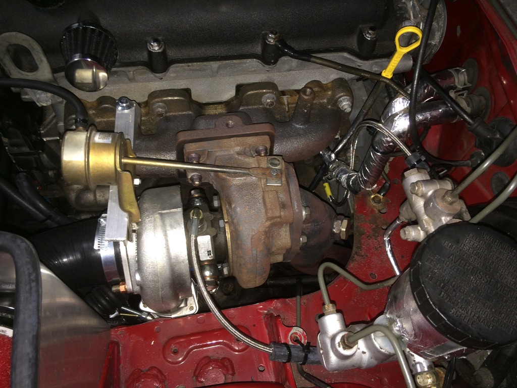
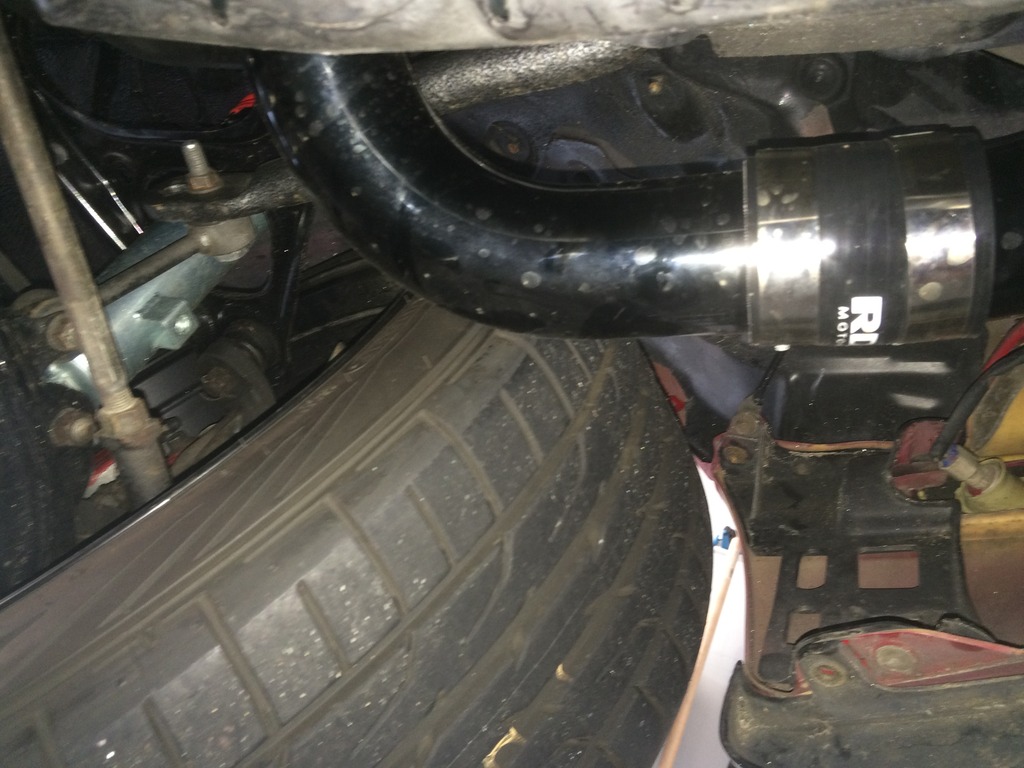
Just discovered a new issue, hot side piping makes contact with the tire. Glad I caught this. Will need to shorten some of the pipes. Too bad that will mean I lose some of the beaded ends of the pipe.
I am located in Fairfax, VA.
Just discovered a new issue, hot side piping makes contact with the tire. Glad I caught this. Will need to shorten some of the pipes. Too bad that will mean I lose some of the beaded ends of the pipe.

Reply
0
0
 08-01-2016, 09:49 AM
#18
Junior Member
Thread Starter
iTrader: (1)
Join Date: Dec 2015
Location: Fairfax, VA
Posts: 143
Total Cats: 41
Does anyone from the area have any recommendations on a local exhaust shop? I've talked to Roberts in Stafford, Hi-flo in Manassas and EB3 in Manassas. None of the shops do mandrel bending but they should all be able to get mandrel pieces. Price quotes have varied.
Reply
0
0

 08-02-2016, 04:17 AM
#20
Junior Member

Join Date: Oct 2015
Location: Stockholm, Sweden
Posts: 89
Total Cats: 11
Looks nice and neat. I have the very same turbo and manifold (SR20 GT2560R and TacoTacoTaco) lying on a shelf awaiting install. When I measured things out (sloppily, with stock exhaust still in car) it seemed like I would not quite be able to run the compressor outlet downwards and would have to go sideways or up, but I guess your build is counter-proof to that. How much clearance is there between the compressor housing and the car body? It looks like it's somewhere around 6-8mm, and in that case I'd be worried it could hit when the engine moves around. Have you noticed any such issues?
Reply
0
0


