intake manifold design....
 10-11-2013, 11:33 PM
#1
Senior Member
Thread Starter
iTrader: (2)

Join Date: Oct 2011
Location: Hickory, NC
Posts: 675
Total Cats: 9
I know this topic has been beaten to death.....but lets beat a little more
I have searched, and read all I found regarding intake manifold design since I am going to build my own. In one thread Savington told someone to search for why plenum is important, Brain replied in such a way that suggested the subject had been talked about in great length.....however I was unable to find any thread about the plenum design.
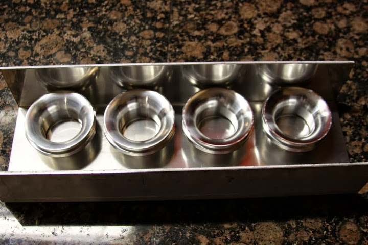
I bought the velocity stacks from Ross Machine Racing, had some 2" OD aluminum mandrel bent so I can get the length of runner wanted without hitting shock tower. I was able to find lots of great information from my searching but think there is more to learn and ask that we discuss this again. I will flow the manifold on a flow bench to ensure all cylinders flow equal, or as equal as to be expected. How close is close enough in regards to equal flow?
I have read the plenum should be at least 150% the volume of the engine displacement. I have also read un-throttled volume equals poor throttle response. So where is the happy medium? I know the bigger it is the more likely it is to have equal flow throughout the cylinders, but not sure what I should aim for? I read the plenum should extend well beyond the last runner. How far is "well"?
I plan to do a raised runner design in hopes of equalizing flow. How far do I need to go, thoughts?
I read the plenum should "quickly and rapidly expand in volume" (in regards to the charge pipe) to slow the incoming charge to reduce the effect of starving the first cylinder. Should this be tapered to reduce turbulence? Or can it be a 3" whole (for TB) on a 5" plate?
Future designs may include a tapered runner, but for this discussion lets stick to a constant diameter.
In an effort to avoid the cracking welds some have seen when doing the honda/mazda manifold fab, I plan to use the same alloy (6061) for all parts. It has been suggested that we really have no idea what alloy mazda used, nor do we know what Blox used.
I would also like to hear your thoughts on TB size.
Would you daily drive a car without an IAC? I did for a year and it is a real pain in the dick! Thoughts on using an IAC valve with custom manifold?
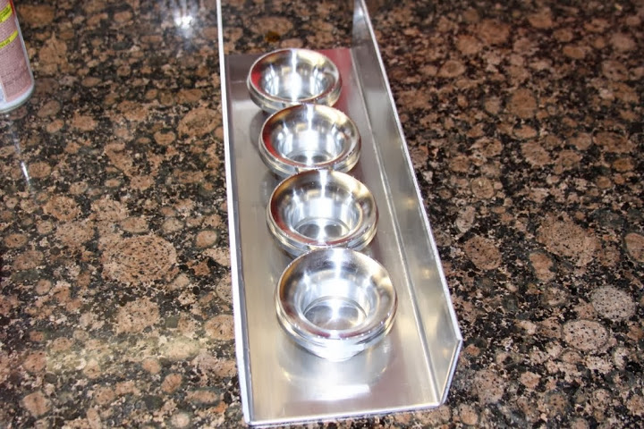
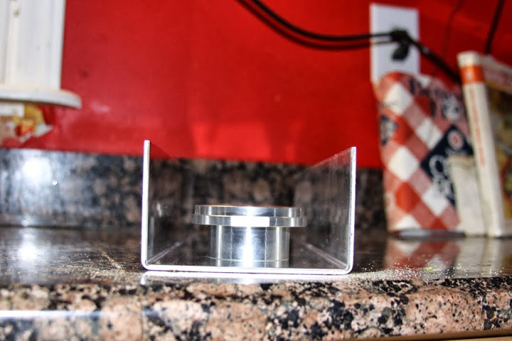
The stacks are 1.5" tall and 3" I plan to use a 5" wide channel with half of a 5" OD pipe welded to it creating a "D" shape. I plan to taper it some, not sure how much taper....thoughts?
Do you think it matters if the stacks are centered or can I offset them to one side to make fitment easier?

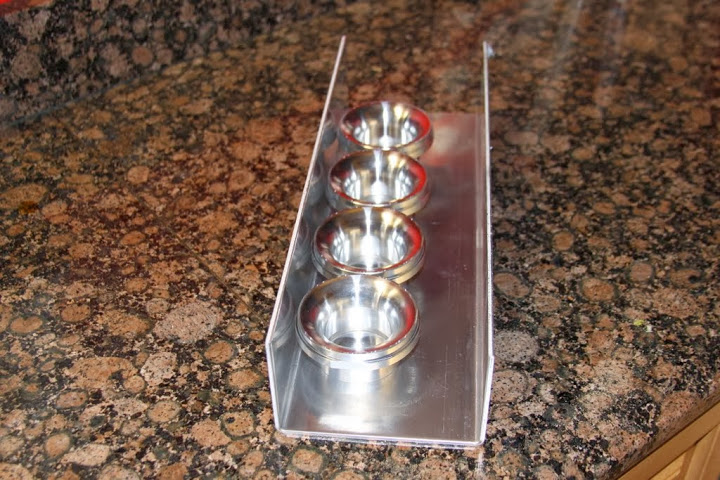
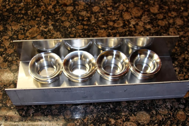
What are your thoughts on the stacks touching each other versus spread out a little? I assume they will flow better with some space between them but I want some room before the first and after the last runner.
Thanks for your input! After assembled I will not only measure the variance of flow between cylinders, I will try to get video of smoke flowing through the manifold to see where turbulence is and possibly cut the sumbitch apart and start over.....
I have searched, and read all I found regarding intake manifold design since I am going to build my own. In one thread Savington told someone to search for why plenum is important, Brain replied in such a way that suggested the subject had been talked about in great length.....however I was unable to find any thread about the plenum design.
I bought the velocity stacks from Ross Machine Racing, had some 2" OD aluminum mandrel bent so I can get the length of runner wanted without hitting shock tower. I was able to find lots of great information from my searching but think there is more to learn and ask that we discuss this again. I will flow the manifold on a flow bench to ensure all cylinders flow equal, or as equal as to be expected. How close is close enough in regards to equal flow?
I have read the plenum should be at least 150% the volume of the engine displacement. I have also read un-throttled volume equals poor throttle response. So where is the happy medium? I know the bigger it is the more likely it is to have equal flow throughout the cylinders, but not sure what I should aim for? I read the plenum should extend well beyond the last runner. How far is "well"?
I plan to do a raised runner design in hopes of equalizing flow. How far do I need to go, thoughts?
I read the plenum should "quickly and rapidly expand in volume" (in regards to the charge pipe) to slow the incoming charge to reduce the effect of starving the first cylinder. Should this be tapered to reduce turbulence? Or can it be a 3" whole (for TB) on a 5" plate?
Future designs may include a tapered runner, but for this discussion lets stick to a constant diameter.
In an effort to avoid the cracking welds some have seen when doing the honda/mazda manifold fab, I plan to use the same alloy (6061) for all parts. It has been suggested that we really have no idea what alloy mazda used, nor do we know what Blox used.
I would also like to hear your thoughts on TB size.
Would you daily drive a car without an IAC? I did for a year and it is a real pain in the dick! Thoughts on using an IAC valve with custom manifold?
The stacks are 1.5" tall and 3" I plan to use a 5" wide channel with half of a 5" OD pipe welded to it creating a "D" shape. I plan to taper it some, not sure how much taper....thoughts?
Do you think it matters if the stacks are centered or can I offset them to one side to make fitment easier?
What are your thoughts on the stacks touching each other versus spread out a little? I assume they will flow better with some space between them but I want some room before the first and after the last runner.
Thanks for your input! After assembled I will not only measure the variance of flow between cylinders, I will try to get video of smoke flowing through the manifold to see where turbulence is and possibly cut the sumbitch apart and start over.....

Reply
 0
0

0
10-11-2013, 11:42 PM
#2

just a thought.
those velocity stacks look sexy.
Reply
0
0
10-11-2013, 11:50 PM
#3
Senior Member
Thread Starter
iTrader: (2)
Join Date: Oct 2011
Location: Hickory, NC
Posts: 675
Total Cats: 9
I forgot to ask, when figuring the runner length, where do I start in regards to the velocity stack? Is it at the top? Or at the end of the taper where it reaches the runner ID?
I found, in a thread on here that came up while searching, a intake manifold calculator that tells you the length of the runner based on cam duration. So what value do I use for duration since it is VVT? I know this is not a fair question since it will change based on tune, but can someone please give me a value that will be close?
I found, in a thread on here that came up while searching, a intake manifold calculator that tells you the length of the runner based on cam duration. So what value do I use for duration since it is VVT? I know this is not a fair question since it will change based on tune, but can someone please give me a value that will be close?
Reply
0
0
10-12-2013, 03:33 AM
#5

Hi Chris, I've been thinking a lot about this too. In the Honda manifold thread, it was said runner length should be 10.5" from where it starts being a runner (top of valve) to where it stops being a runner at the plenum according to 949. A place to start anyway. There's a lot of stuff out there = confusing. AMS has a really cool design.
AMS Mitsubishi Lancer Evolution VIII | IX F1-I Intake Manifold
Also Magnus,
Intake Manifolds | Magnus Motorsports
Speedtalk has this:
Google Image Result for http://i103.photobucket.com/albums/m127/Deltona_II/Plenums%20and%20air%20intake%20etc/ec127d1e.jpg
I was also thinking about using an end from an intercooler to get the taper.
VECCO High Performance
There also dual plenum designs. (Refer to the Speedtalk thread)
Whatever you decide for plenum design, it would be interesting to come up with a way to vary the runner length (maybe silicon hose) and see how runner length effects horsepower/torque.
Reply
0
0

 10-12-2013, 10:23 PM
#8

I would keep the stacks as far apart as you can get away with. You also dont want them touching the wall. Remember, velocity on the wall is zero, which is why you want the velocity stacks raised off the plenum floor.
When you taper the plenum you want to reduce the flow cross section as you have less cylinders flowing through it. This helps keep the flow more even.
Plenum volume is black magic unless you can do cfd. And even then... I only know how to optimize one on an N/A engine with a required intake restrictor. Which actually makes the optimization easier when you have that design restriction.
TB, I wouldnt go bigger than 65mm unless you are trying to make absurd power. And Taper wise, you want to use a 3.5* angle (7* included angle) taper. If you have the room to fit that since thats typically the optimal angle for a diffuser in an intake system for drawing air through an orifice, though ymmv with the size piping we're talking about.
Reply
0
0
10-12-2013, 10:43 PM
#9
Elite Member
iTrader: (1)

Join Date: May 2009
Location: Jacksonville, FL
Posts: 5,155
Total Cats: 406
I found some information that basically shows that when it comes to power, the more plenum volume the better. Their were small gains all the way to like 8 times displacement before they stopped.
In the Honda world, this is one of the best performaing manifolds:
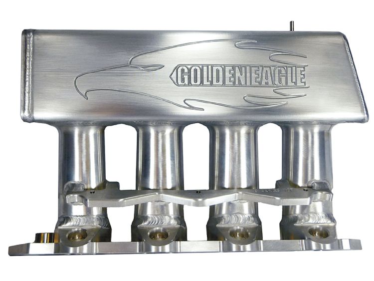
Its funny because it does not have a very good plenum shape, but the big volume works well. Im not sure about throttle response though.
+1 on the <65mm TB.
Ive worked on several cars with 70mm throttles and they are awful. It just makes everything harder and its totally unnecessary.
Id suggest a stock 62mm Honda TB.
In the Honda world, this is one of the best performaing manifolds:
Its funny because it does not have a very good plenum shape, but the big volume works well. Im not sure about throttle response though.
+1 on the <65mm TB.
Ive worked on several cars with 70mm throttles and they are awful. It just makes everything harder and its totally unnecessary.
Id suggest a stock 62mm Honda TB.
Reply
0
0
10-12-2013, 10:49 PM
#10
The oversimplified explanation of the plenum tradeoff is the engine has to use up the volume of air in the plenum before it reacts to throttle changes. Yes thats now how it actually works in the science but its easier to comprehend when just brainulizing a design. It has more to do with how fast the volume can be filled based on the pressure currently outside the throttle body when opened, and how long it takes the engine to use the air in the plenum after you close the throttle.
Reply
0
0
10-13-2013, 10:58 AM
#12
Elite Member
iTrader: (1)
Join Date: May 2009
Location: Jacksonville, FL
Posts: 5,155
Total Cats: 406
Pretty much exactly what Leafy just said. More volume will smooth out the volume of air inside the plenum as it is consumed by each intake stroke.
The Effects of Intake Plenum Volume on the Performance of a Small Normally Aspirated Restricted Engine
The Effects of Intake Plenum Volume on the Performance of a Small Normally Aspirated Restricted Engine
Testing was conducted on a four cylinder 600 cc motorcycle engine... Plenum sizes were varied from 2 to 10 times engine displacement (1.2 to 6.0 L) and engine speeds were varied from 3,000 to 12,500 RPM...
Experimental results showed that engine performance increased modestly as plenum volume was increased from 2 to 8 times engine displacement. Increasing plenum volume beyond 8 times engine displacement resulted in significant improvement in performance parameters. Overall, peak HP was shown to increase from 54 kW to 63 kW over the range of plenums tested.
While it was clear that larger intake plenums yielded better steady state performance, their effect on transient performance was not explored and will be the subject of further research.
Reply
0
0
10-14-2013, 08:14 AM
#13
Former Vendor

Join Date: Dec 2007
Location: Texas Hill Country
Posts: 271
Total Cats: 11
I've not seen any change in throttle response with plenum size. All the events simply happen too fast. Keep in mind that just 1200 rpm is 10 putts per sylable per second. Young Mr. Vettel might detect a change, but not me.
If the air horns are placed more than maybe .5 inch from the back wall, the horns ought to flare as much as 180 degrees to assist the air that passes behind the flare.
2% in flow variation is a common objective.
Several tries with runners of 17+ inches and curves brought up the mid range (4k r's) a bit but not enough for the lower gain from there up. 7 to 8 inches from the head works best for me.
9% at peak is about the best I've seen.
The bigger throttle proves worth the cost, but I don't remember the numbers. One cool fringe benefit to the bigger throttle is the perceived throttle response. With a bigger throttle bore, and the same pedal stroke, the rate of change of the flow area is initially much quicker. It adds another nice dose of eagerness to the already eager to run Miata motor.
A brace and no grinding welds flat will usually keep the welds alive. Bevels before welding, of course.
Using flat panel in the plenum can be a problem. "oil canning" of the flats can cause weld failure in no time. Well, "some" time. A flat panel of 4" x 16" with 15 psi boost gets pushed with 960 pounds. The major stress in flat panel bending occurs at the egdes.
If one wants to make his own air horns, try machining a die, annealing the tube, then press the two together. Polish up by spinning on a lathe. Annealing aluminum is shaky, but call me and I'll tell you how. 830-438-2890.
corky
Reply
1
1
10-14-2013, 08:25 AM
#16
The bigger throttle proves worth the cost, but I don't remember the numbers. One cool fringe benefit to the bigger throttle is the perceived throttle response. With a bigger throttle bore, and the same pedal stroke, the rate of change of the flow area is initially much quicker. It adds another nice dose of eagerness to the already eager to run Miata motor.
Reply
0
0
10-14-2013, 09:58 AM
#17
Senior Member
Thread Starter
iTrader: (2)
Join Date: Oct 2011
Location: Hickory, NC
Posts: 675
Total Cats: 9
Lots of great information guys, thanks a lot! Please, keep the discussion going....
I was worried I was making the plenum too big but now I feel better about it. I need to figure out my TB.....I want to retain an IAC as this is a daily driver. I want to find out more about the Ford 4.6 TB that has IAC built in like ours does.....I think that may be a winner!
I was worried I was making the plenum too big but now I feel better about it. I need to figure out my TB.....I want to retain an IAC as this is a daily driver. I want to find out more about the Ford 4.6 TB that has IAC built in like ours does.....I think that may be a winner!
Reply
0
0

 10-14-2013, 11:22 AM
#19
I've not seen any change in throttle response with plenum size. All the events simply happen too fast. Keep in mind that just 1200 rpm is 10 putts per sylable per second. Young Mr. Vettel might detect a change, but not me.
If the air horns are placed more than maybe .5 inch from the back wall, the horns ought to flare as much as 180 degrees to assist the air that passes behind the flare.
2% in flow variation is a common objective.
Several tries with runners of 17+ inches and curves brought up the mid range (4k r's) a bit but not enough for the lower gain from there up. 7 to 8 inches from the head works best for me.
9% at peak is about the best I've seen.
The bigger throttle proves worth the cost, but I don't remember the numbers. One cool fringe benefit to the bigger throttle is the perceived throttle response. With a bigger throttle bore, and the same pedal stroke, the rate of change of the flow area is initially much quicker. It adds another nice dose of eagerness to the already eager to run Miata motor.
A brace and no grinding welds flat will usually keep the welds alive. Bevels before welding, of course.
Using flat panel in the plenum can be a problem. "oil canning" of the flats can cause weld failure in no time. Well, "some" time. A flat panel of 4" x 16" with 15 psi boost gets pushed with 960 pounds. The major stress in flat panel bending occurs at the egdes.
If one wants to make his own air horns, try machining a die, annealing the tube, then press the two together. Polish up by spinning on a lathe. Annealing aluminum is shaky, but call me and I'll tell you how. 830-438-2890.
corky
If the air horns are placed more than maybe .5 inch from the back wall, the horns ought to flare as much as 180 degrees to assist the air that passes behind the flare.
2% in flow variation is a common objective.
Several tries with runners of 17+ inches and curves brought up the mid range (4k r's) a bit but not enough for the lower gain from there up. 7 to 8 inches from the head works best for me.
9% at peak is about the best I've seen.
The bigger throttle proves worth the cost, but I don't remember the numbers. One cool fringe benefit to the bigger throttle is the perceived throttle response. With a bigger throttle bore, and the same pedal stroke, the rate of change of the flow area is initially much quicker. It adds another nice dose of eagerness to the already eager to run Miata motor.
A brace and no grinding welds flat will usually keep the welds alive. Bevels before welding, of course.
Using flat panel in the plenum can be a problem. "oil canning" of the flats can cause weld failure in no time. Well, "some" time. A flat panel of 4" x 16" with 15 psi boost gets pushed with 960 pounds. The major stress in flat panel bending occurs at the egdes.
If one wants to make his own air horns, try machining a die, annealing the tube, then press the two together. Polish up by spinning on a lathe. Annealing aluminum is shaky, but call me and I'll tell you how. 830-438-2890.
corky
I thought I read that 62-65mm was about the best compromise. Above that, midrange throttle response suffers and it becomes more of an off/on problem. I've noticed throttle bodies from Audis and BMWs have two slightly progressive butterflies (one small, one large) that may be worth research.
I plan on more research on the 4G63/EVO intake and exhaust manifolds as a option over Honda. It is a very well supported supported platform and could be better choices over the honda intakes.
-JB
Reply
0
0


