Tach signal and wiring specifics
 06-20-2011, 01:24 PM
#1
Elite Member
Thread Starter
iTrader: (8)

Join Date: Jun 2008
Location: WNC
Posts: 1,648
Total Cats: 55
Posted in this thread last week but perhaps it didn't get noticed as the title is not directly related to my problem, so I'll start a new thread 
My tach is currently inop after my ECU/harness swap. Underdog has the same issue on the same setup and he warned me that I'd have to dig around for a solution. For reference, I do still have the stock ecu and igniter connected to the stock harness, but it's no longer part of the ignition system. The Miata and DSM igniters are nearly identical, one exception is the DSMs lack of the IGf pin (Mitsu J702T vs Mitsu J722T). I need to look further into how the DSM tach works, but the ignition is also a wasted spark 1/4, 2/3 setup as in the Miata so it's pretty damn similar I'd suspect.
*Since posting in that other thread I've discovered that the DSM uses a 5V square signal to feed the tach. What does the Miata tach signal actually look like? Is it a 12V signal all the way to the tach, or?? I can't find anything here or m.net about the actual signal voltage. Simply connecting the Miata tach feed at the ignitor harness to the DSM signal output at the DSM igniter does not work. I also found that the tach signal in the DSM setup splits from the igniter and goes to both the tach and ECU, but thus far nobody in DSM land can tell me what that split to the ECU does. I do have engine rpms showing up in my logs, so I'm guessing that it's just a signal feed for the ecu to monitor.
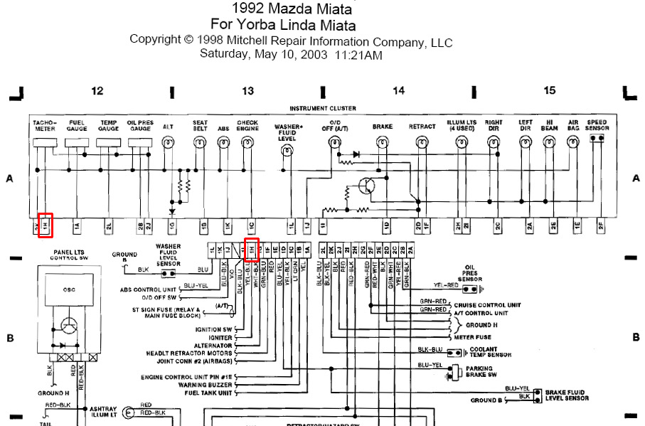
The info from Joe in the above linked thread is very helpful, but another thing I'm needing to know now is about the actual wire to the tach. Based on the wiring diagram shown below for a stock '92, it looks like the signal wire goes directly from the igniter to the tach (1H, yel-blu), without passing through the ecu. Is this correct? There is also a wire dropping off the tach that appears to be a common power source that runs to the meter fuse (2K, blk-yel), but all my other gauges work so I'd guess that the problem does not lie there.
Also, does the signal from the ecu to IGf do anything other than supply the pullup for the tach signal? If yes, what?
Thanks!
My tach is currently inop after my ECU/harness swap. Underdog has the same issue on the same setup and he warned me that I'd have to dig around for a solution. For reference, I do still have the stock ecu and igniter connected to the stock harness, but it's no longer part of the ignition system. The Miata and DSM igniters are nearly identical, one exception is the DSMs lack of the IGf pin (Mitsu J702T vs Mitsu J722T). I need to look further into how the DSM tach works, but the ignition is also a wasted spark 1/4, 2/3 setup as in the Miata so it's pretty damn similar I'd suspect.
*Since posting in that other thread I've discovered that the DSM uses a 5V square signal to feed the tach. What does the Miata tach signal actually look like? Is it a 12V signal all the way to the tach, or?? I can't find anything here or m.net about the actual signal voltage. Simply connecting the Miata tach feed at the ignitor harness to the DSM signal output at the DSM igniter does not work. I also found that the tach signal in the DSM setup splits from the igniter and goes to both the tach and ECU, but thus far nobody in DSM land can tell me what that split to the ECU does. I do have engine rpms showing up in my logs, so I'm guessing that it's just a signal feed for the ecu to monitor.
The info from Joe in the above linked thread is very helpful, but another thing I'm needing to know now is about the actual wire to the tach. Based on the wiring diagram shown below for a stock '92, it looks like the signal wire goes directly from the igniter to the tach (1H, yel-blu), without passing through the ecu. Is this correct? There is also a wire dropping off the tach that appears to be a common power source that runs to the meter fuse (2K, blk-yel), but all my other gauges work so I'd guess that the problem does not lie there.
Also, does the signal from the ecu to IGf do anything other than supply the pullup for the tach signal? If yes, what?
Thanks!

Reply
 0
0

0
06-20-2011, 01:31 PM
#2
Boost Czar


iTrader: (62)
Join Date: May 2005
Location: Chantilly, VA
Posts: 79,488
Total Cats: 4,077
the ECU has nothing to do with your tach signal to your dash. However, it does provide the pull-up to power to the tach output wire from your coils (the black/white wire from 2I to the ignitor).
Grab a 1K resistor, jump IG- with B+ in the diagnostics box, and enjoy the tach again.
Grab a 1K resistor, jump IG- with B+ in the diagnostics box, and enjoy the tach again.
Reply
0
0
06-20-2011, 01:44 PM
#3
Elite Member
Thread Starter
iTrader: (8)
Join Date: Jun 2008
Location: WNC
Posts: 1,648
Total Cats: 55
Thanks for the quick response, especially verifying that the stock ECU does not intercept the tach signal.
However, I want to be sure that the fact that the stock Miata ignition system is not connected to the motor in any way won't alter your solution. The stock coils are gone, and the igniter while still attached to the harness is no longer being used. The CAS is also now wired into my new harness. This would lead me to believe that there is no rpm input provided anywhere to the stock Miata harness now.
Could it be as simple as jumping my existing tach signal (from my new harness/igniter) to the Miata igniter harness to get that signal back into the Miata engine harness, then doing what you describe above?
Reply
0
0
 06-20-2011, 01:57 PM
#5
Elite Member
Thread Starter
iTrader: (8)
Join Date: Jun 2008
Location: WNC
Posts: 1,648
Total Cats: 55
Yeah, I'll give that a shot since it's simple enough. The car is running so I'm pretty sure the coils are hooked up properly. Just to restate, nothing related to the ignition is currently connected to the Miata harness.
Edit: Any particular wattage I need to use? I see that there are 1/4, 1/2, etc watt 1K ohm resistors out there.
Edit: Any particular wattage I need to use? I see that there are 1/4, 1/2, etc watt 1K ohm resistors out there.
Last edited by matthewdesigns; 06-20-2011 at 02:09 PM.
Reply
0
0
 06-20-2011, 10:02 PM
#10
Elite Member
Thread Starter
iTrader: (8)
Join Date: Jun 2008
Location: WNC
Posts: 1,648
Total Cats: 55
Somebody's gonna get a kiss 
Took a break from work, ran to Radio Shack for the resistor, and tried jumping the pins in the diagnostic connector, but that alone did not bring the tach to life. However, after patching the DSM tach signal into the Miata harness via the ignitors' tach connectors it works! I have not verified that it's correct with a log of the ECU, but it sure looks right from the driver's seat.
Thanks Brain!
And for the sake of not being totally ghetto I'll eventually get around to wiring the resistor in behind the diag box, but is it OK just stuck in there until that happens? Maybe a couple weeks?
Reply
0
0
08-15-2011, 06:47 PM
#11

sorry to dig this up, but i have a tach situation also. i have a '95 1.8 with a stock harness and link ecu. i had a problem with the needle jumping around crazy and finally stopped working a long time ago. that turned out to be the ground by the t-body. fixed it and tach was fine again. this time i went to drive one day and no tach. i checked all the grounds and all looked good. then tried a shift light with digital tach readout, first to the diag. box, then even at the ecu (blk./wht. stripe) and still nothing. thinking maybe the electronic shift light/tach wasn't compatible, i tried a basic autometer tach on it, again both locations, still no go. finally i tried tapping the wire at the coil for a signal and still didn't work. originally i thought the ecu was putting out the signal, as the wire goes to both coils, tach, and the diag. box. but is it really the coil that provides the output? is it my coil that isn't providing a signal? can i try the 1k resistor also? if not, is there any other way to "generate" a signal? like the op, my link shows/logs rpm, but that doesn't help while on the track.
Reply
0
0
08-17-2011, 01:13 PM
#14
Boost Pope

iTrader: (8)
Join Date: Sep 2005
Location: Chicago. (The less-murder part.)
Posts: 33,017
Total Cats: 6,587
(as far as tach signal) i really don't feel like buying another coilpack. is there any other way to "generate" a tach signal?
what do people that go COP do for a tach?
Reply
0
0
 i guess i'll try your circuit build or atleast try and figure out what you're describing. thanks, joe.
09-20-2011, 09:31 AM
i guess i'll try your circuit build or atleast try and figure out what you're describing. thanks, joe.
09-20-2011, 09:31 AM
#16
Newb

Join Date: Jul 2011
Location: Rehoboth, MA
Posts: 17
Total Cats: 0
i have been talking with matt. i put link in my 91. and i spoke with him and put the resistor into the diag port and hooked up the tach input up to the ignitor....nothing. i tried putting the miata ecu back in the car and powering it up because he still has his miata ecu in there. nothing. so ive come to the conclusion that i fudged something up. what does that resistor actually connect? because if i can figure out what those two wires are supposed to be. i can just manually wire something up. and i saw the post about making that circuit and i couldnt tell you what any of that means.
but what im getting from it is to have a 12v source inline with the tach signal line. with the 1k resistor between them so in between the coils firing it is getting a 12v signal vs a 5v
but what im getting from it is to have a 12v source inline with the tach signal line. with the 1k resistor between them so in between the coils firing it is getting a 12v signal vs a 5v
Last edited by JFontaine; 09-20-2011 at 09:47 AM.
Reply
0
0
09-21-2011, 12:52 AM
#17
yeah, i'm no electronics technician, so i'll probably have a buddy try and make one for me or something. i gave up for now. I ended up buying one of those cigarette lighter plug-n-play shift lights. it's hard to set the first time, but worked as advertised at the last event. only bad part is it feels really cheap, hope it lasts a while.
Reply
0
0
09-21-2011, 11:35 AM
#18
Elite Member
Thread Starter
iTrader: (8)
Join Date: Jun 2008
Location: WNC
Posts: 1,648
Total Cats: 55
Howdy Jay. Make an intro thread or nobody is going to take you seriously. You've got a cool project with a great swap coming up, I'm sure there are plenty of members here who would like to see it.
No luck with the tach adapter, or have you not tried that yet? It's strange that yours is not working if everything is connected the same way as mine, unless you pulled some critical bit out with the harness removal. Frankly I feel like I got lucky, and I never felt like I got enough info about the DSM ECU/tach signal to figure it out if it had not worked.
And by Link, he means ECMLink, same as what me and Underdog are using, not a Link ECU for Miata. Just in case anybody tries to answer this.
Also should note that his car runs, and he can log RPM, so there's a signal getting to the DSM ECU. This is where I got stumped, but the diag box resistor jumper worked for me.
Reply
0
0
09-21-2011, 02:03 PM
#20
Elite Member
Thread Starter
iTrader: (8)
Join Date: Jun 2008
Location: WNC
Posts: 1,648
Total Cats: 55
Brain, are you saying the Miata ecu has nothing to do with the tach operation? That's been my impression after digging around wiring schematics, I just want to be sure as I may be pulling mine out since I'm thinking it's not doing anything but adding weight at this point.
Reply
0
0


