
TinyIOx


MS3X, MS3-Pro, or MSPNP-Pro have enough I/O for most 'standard' type builds, but as you get into higher forms of motorsports, your I/O needs grow at a near exponential rate, hence the need for CAN enabled expansion boxes. Here is a basic list of some of the inputs that customers request:
- 2 to 4 wheel speed, depending on application
- Brake switch or brake pressure
- steering angle
- suspension travel x4
- coolant pressure
- oil temp & pressure
- fuel temp & pressure
- pre & post intercooler temp
- turbine inlet pressure
- wb02 per cylinder
- EGT per cylinder
- nitrous pressure
- IR temp sensors, usually tire temp or track temp
- crankcase pressure
- cylinder head temp

Reply
 0
0

0
Too many sensors, the thought of doing all the wiring makes me cry.
Now I know why I see 2-3 or more sets of 28 pin firewall bulkhead connectors on some cars...
Is the MS3 better at basic programming off all these inputs? I'm not sure that's the best phrasing for it, but with my MS2 it seems I can't tell it to adjust anything in the tune off any custom adcs I might add.
Assuming I want to add an oil temperature sensor to cut RPM if it rises above a certain temperature, I don't even see a way to do that on my MS2. Is the MS3 able to do more with all these extra inputs, are they just for datalogging, or am I just missing something?
I mean I guess I could build a circuit to cut into the coolant sensor and cut the signal, that should max out 255 and a CLT based rev limiter off oil temp.
There'd be no way for me to pull timing by comparing a front and rear ADC from wheel speed sensors though, as a rough example, pretty sure the ms3 can do that naitivly, but would it be able to pull timing if it measured excessive EGT on one cylinder in comparison to the rest or something?
Reply
0
0

This looks like a fun project... Couple questions if anyone here knows the answer.
It says it can process the LC1 serial wideband input. Can it do AEM wideband serial as well?
Is there a way to get the ADC inputs to broadcast out over CAN via the dashboard broadcast mode? I'd like to get oil temp and oil pressure out.
It says it can process the LC1 serial wideband input. Can it do AEM wideband serial as well?
Is there a way to get the ADC inputs to broadcast out over CAN via the dashboard broadcast mode? I'd like to get oil temp and oil pressure out.
Reply
0
0
Thread Starter

Joined: Apr 2014
Posts: 18,643
Total Cats: 1,870
From: Beaverton, USA
You need custom code to do the revlimiter for oil temp.
I'm going to write it this winter at some point. I found where the revlimiter is, just need to figure out how to use the variables and memory. And connect to the ini files.
I'm going to write it this winter at some point. I found where the revlimiter is, just need to figure out how to use the variables and memory. And connect to the ini files.
Reply
0
0
Yes, if you use the full CAN broadcast mode. The simple dash mode was designed for people who have a hard time making a sandwich. Use the full mode, and the sensor data is broadcastable as soon as you assign the ADC as a sensor input.
Reply
0
0
All-round "Good Guy"

Joined: Dec 2009
Posts: 1,035
Total Cats: 266
From: Brisbane, AUSTRALIA
WARNING: Ensure that your 2.5mm jack is held securely and will not vibrate much, otherwise you risk tearing the socket off the board.
The socket is only mounted, via solder, to 3 pads on the surface of the board - it SHOULD be mounted via pins that pass through the board and soldered on the underside:
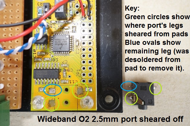
I found this when mounting my sensor box in my glovebox and I couldn't "find" the socket when trying to insert the Innovate WideBand O2 2.5mm plug, two of the three legs had sheared off the mount pads and it was bent, held by the remaining leg.
Those 2 vertical holes you see between the solder pads are merely locating slots, the port's underside has 2 posts that slot into them - they do NOT fasten the port to the board!
I loved this board but it's not suitable for vehicle use since vibrations will eventually tear those pads off the board no matter how secure you make the plug.
If you are using this board, use a zip-tie over the port to secure it to the board so that you're not relying on the soldered legs, to the surface pads, to hold it in place.
Reply
0
0

I have 3 that I hope to integrate (MS2) this winter. Sub'd.
oh and don't ziptie, use glue like we do in industry for reliability. Silicone for resonance failures, epoxy for stress. BTW, this is stress.
oh and don't ziptie, use glue like we do in industry for reliability. Silicone for resonance failures, epoxy for stress. BTW, this is stress.
Reply
0
0
You could even use JB weld if you want. Pretty much any decently low viscosity 2 part that bonds to plastics will work wonders. Run a bead along the edges and then fill the 2 positioning holes on the bottom.
you dont need much
you dont need much
Reply
0
0
All-round "Good Guy"
Joined: Dec 2009
Posts: 1,035
Total Cats: 266
From: Brisbane, AUSTRALIA
There are no pads remaining where I've circled in green, they've sheared right off with the legs, so there's nothing to solder the legs to.
If you have one of these boards, be proactive, de-solder the legs, "glue" the underside of the jack port to the board, then re-solder the legs to the pad.
- You can see in my photo, based on how clean the base is, that there was nothing used to hold the jack port other than the soldered legs, definitely not good enough for vehicle use.
Reply
0
0
Thread Starter
Joined: Apr 2014
Posts: 18,643
Total Cats: 1,870
From: Beaverton, USA
There are no pads remaining where I've circled in green, they've sheared right off with the legs, so there's nothing to solder the legs to.
If you have one of these boards, be proactive, de-solder the legs, "glue" the underside of the jack port to the board, then re-solder the legs to the pad.
- You can see in my photo, based on how clean the base is, that there was nothing used to hold the jack port other than the soldered legs, definitely not good enough for vehicle use.
If you have one of these boards, be proactive, de-solder the legs, "glue" the underside of the jack port to the board, then re-solder the legs to the pad.
- You can see in my photo, based on how clean the base is, that there was nothing used to hold the jack port other than the soldered legs, definitely not good enough for vehicle use.
Reply
0
0

Desoldering not required.
if the traces going to the pads are on the top layer, use an exacto to scrape the soldermask off a short section of the trace. Solder blue wire from the exposed trace to the component lead. Use CA or hot glue to protect and secure the blue wire and exposed trace.
Presto.
if the traces going to the pads are on the top layer, use an exacto to scrape the soldermask off a short section of the trace. Solder blue wire from the exposed trace to the component lead. Use CA or hot glue to protect and secure the blue wire and exposed trace.
Presto.
Reply
0
0

Thread
Thread Starter
Forum
Replies
Last Post
Zaphod
MEGAsquirt
47
Oct 26, 2018 11:00 PM
thumpetto007
General Miata Chat
2
Oct 26, 2015 12:58 AM


