MS3X help. No 12V at U5
 06-16-2016, 10:16 PM
#1
Senior Member
Thread Starter
iTrader: (8)

Join Date: Jan 2012
Location: Azusa, CA
Posts: 1,407
Total Cats: 116
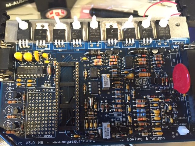
I'm at the step of checking voltages of my MS3 build. I have 12V into Pin 28 and GND to Pin 1.
I do not have 12V at pin 40 of U1 and I do not have 5V at the proper places at U1.
When I traced the 12V line I was able to follow it and I do have 12V at IAC1B, JS1 and pin 37 of U1.
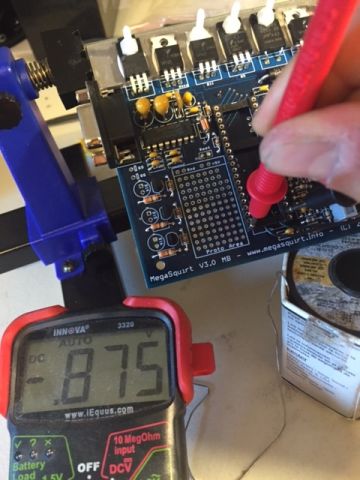
I do not have 12V at U5. I've checked the diodes and they all look to be in the proper orientation. I do not have 12V at any of diodes D10-D13 which has me confused....
Any ideas of whats going on or what to try next?

I do not have 12V at pin 40 of U1 and I do not have 5V at the proper places at U1.
When I traced the 12V line I was able to follow it and I do have 12V at IAC1B, JS1 and pin 37 of U1.
I do not have 12V at U5. I've checked the diodes and they all look to be in the proper orientation. I do not have 12V at any of diodes D10-D13 which has me confused....
Any ideas of whats going on or what to try next?

Reply
 0
0

0
06-17-2016, 08:47 AM
#3
Boost Czar


iTrader: (62)
Join Date: May 2005
Location: Chantilly, VA
Posts: 79,490
Total Cats: 4,079
what writeup are you using to build your MS? You've added a ton of parts you don't need and didn't mod it for miata inputs yet.
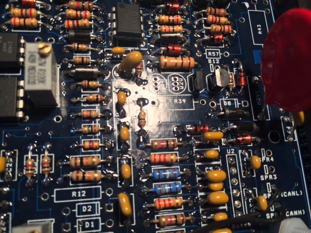
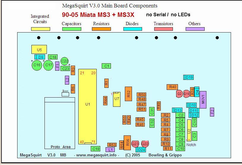
if you dont have 12v at U5, then the problem is a trace on the PCB, 12 goes directly into PIN 1 of U5 from the DB37 connector. Look at the bottom of the board and look at the thick trace for it -- it also hits the middle pin of both the Q9 and Q12 FETs you didnt need to install.
if you dont have 12v at U5, then the problem is a trace on the PCB, 12 goes directly into PIN 1 of U5 from the DB37 connector. Look at the bottom of the board and look at the thick trace for it -- it also hits the middle pin of both the Q9 and Q12 FETs you didnt need to install.
Reply
1
1
06-17-2016, 09:11 AM
#4
Supporting Vendor

Join Date: Sep 2006
Posts: 2,332
Total Cats: 67
To check for a short in the Megasquirt PCB, power up the Megasquirt on a Stimulator or on the car and check the following points for voltage with a multimeter.
You should find the same voltage as the battery voltage on the following points: S12, S12C, the center legs of Q9 and Q12, the left (non-banded) end of D3, the left leg of U5, and the left (banded) end of D9.
You should have 5 volts at the following points: S5, the two +5V holes in the proto area, the right (non-banded) end of D9, the right leg of U5, the left (banded) end of D19, and pins 1, 20, and 31 of the CPU.
Let me know where you find the correct voltages, and where you find the wrong ones
Reply
1
1
06-17-2016, 10:23 AM
#5
Senior Member
Thread Starter
iTrader: (8)
Join Date: Jan 2012
Location: Azusa, CA
Posts: 1,407
Total Cats: 116
what writeup are you using to build your MS? You've added a ton of parts you don't need and didn't mod it for miata inputs yet.
if you dont have 12v at U5, then the problem is a trace on the PCB, 12 goes directly into PIN 1 of U5 from the DB37 connector. Look at the bottom of the board and look at the thick trace for it -- it also hits the middle pin of both the Q9 and Q12 FETs you didnt need to install.
if you dont have 12v at U5, then the problem is a trace on the PCB, 12 goes directly into PIN 1 of U5 from the DB37 connector. Look at the bottom of the board and look at the thick trace for it -- it also hits the middle pin of both the Q9 and Q12 FETs you didnt need to install.
I tried following the trace as far as I could but there's to many components on the board. I'll remove those two FETs off the board tonight..
To check for a short in the Megasquirt PCB, power up the Megasquirt on a Stimulator or on the car and check the following points for voltage with a multimeter.
You should find the same voltage as the battery voltage on the following points: S12, S12C, the center legs of Q9 and Q12, the left (non-banded) end of D3, the left leg of U5, and the left (banded) end of D9.
You should have 5 volts at the following points: S5, the two +5V holes in the proto area, the right (non-banded) end of D9, the right leg of U5, the left (banded) end of D19, and pins 1, 20, and 31 of the CPU.
Let me know where you find the correct voltages, and where you find the wrong ones
You should find the same voltage as the battery voltage on the following points: S12, S12C, the center legs of Q9 and Q12, the left (non-banded) end of D3, the left leg of U5, and the left (banded) end of D9.
You should have 5 volts at the following points: S5, the two +5V holes in the proto area, the right (non-banded) end of D9, the right leg of U5, the left (banded) end of D19, and pins 1, 20, and 31 of the CPU.
Let me know where you find the correct voltages, and where you find the wrong ones
Reply
0
0
06-17-2016, 11:03 AM
#6
Boost Czar
iTrader: (62)
Join Date: May 2005
Location: Chantilly, VA
Posts: 79,490
Total Cats: 4,079
looking again, it's a bit outdated and needs updates on the flyback and Alternator.
i dont like the way he does the harness.
http://westfieldmx5.sgrkempen.be/ms3/99-05-ms3/
i dont like the way he does the harness.
http://westfieldmx5.sgrkempen.be/ms3/99-05-ms3/
Reply
0
0
06-17-2016, 01:10 PM
#7
Senior Member
Thread Starter
iTrader: (8)
Join Date: Jan 2012
Location: Azusa, CA
Posts: 1,407
Total Cats: 116
looking again, it's a bit outdated and needs updates on the flyback and Alternator.
i dont like the way he does the harness.
99 ? 05 MS3 | Frank's Westfield MX5 99 ? 05 MS3 |
i dont like the way he does the harness.
99 ? 05 MS3 | Frank's Westfield MX5 99 ? 05 MS3 |
Should I remove the components that are not shown on this diagram?
Reply
0
0
06-18-2016, 03:37 PM
#8
Senior Member
Thread Starter
iTrader: (8)
Join Date: Jan 2012
Location: Azusa, CA
Posts: 1,407
Total Cats: 116
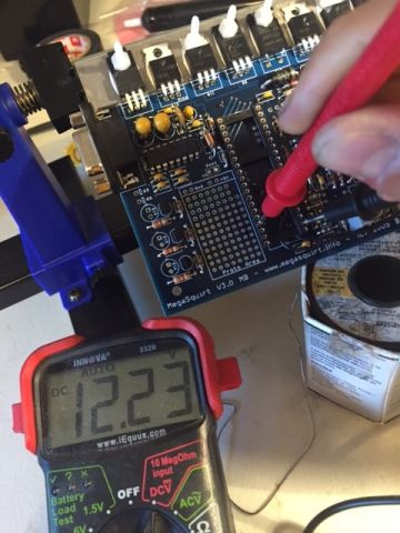
WOW, I made a dumb mistake. I thought I triple checked but I had 12V going into pin27 instead of pin 28 #facpalm
All voltages check out now. Thank you Matt!
Do you recommend removing the not needed components for the miata? or just leave them on the board?
Do you recommend removing the not needed components for the miata? or just leave them on the board?
To check for a short in the Megasquirt PCB, power up the Megasquirt on a Stimulator or on the car and check the following points for voltage with a multimeter.
You should find the same voltage as the battery voltage on the following points: S12, S12C, the center legs of Q9 and Q12, the left (non-banded) end of D3, the left leg of U5, and the left (banded) end of D9.
You should have 5 volts at the following points: S5, the two +5V holes in the proto area, the right (non-banded) end of D9, the right leg of U5, the left (banded) end of D19, and pins 1, 20, and 31 of the CPU.
Let me know where you find the correct voltages, and where you find the wrong ones
You should find the same voltage as the battery voltage on the following points: S12, S12C, the center legs of Q9 and Q12, the left (non-banded) end of D3, the left leg of U5, and the left (banded) end of D9.
You should have 5 volts at the following points: S5, the two +5V holes in the proto area, the right (non-banded) end of D9, the right leg of U5, the left (banded) end of D19, and pins 1, 20, and 31 of the CPU.
Let me know where you find the correct voltages, and where you find the wrong ones
Do you recommend removing the not needed components for the miata? or just leave them on the board?
looking again, it's a bit outdated and needs updates on the flyback and Alternator.
i dont like the way he does the harness.
99 ? 05 MS3 | Frank's Westfield MX5 99 ? 05 MS3 |
i dont like the way he does the harness.
99 ? 05 MS3 | Frank's Westfield MX5 99 ? 05 MS3 |
Reply
0
0
06-18-2016, 04:08 PM
#9
Boost Czar
iTrader: (62)
Join Date: May 2005
Location: Chantilly, VA
Posts: 79,490
Total Cats: 4,079
no leave them. no point on removing.
id just remove r13 and install a 1k between the left pin of r13 and right of r45 just below it. that will provide the 1K pull up for the crank input.
do the jumpers in that writeup.
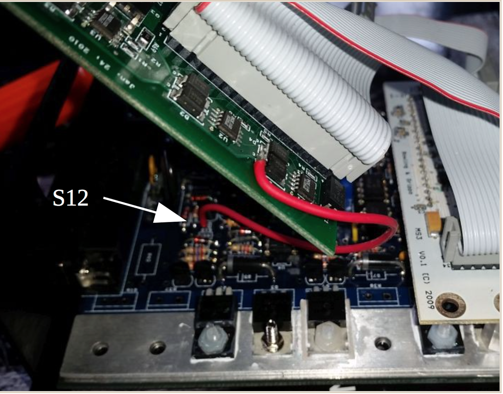
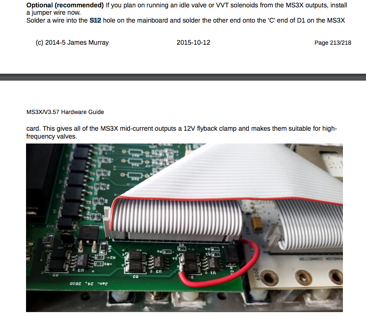
then do the expander board flyback mod. s19 to d1 on the expander.
and then set the pots, and youre pretty much ready to rock and roll.
id just remove r13 and install a 1k between the left pin of r13 and right of r45 just below it. that will provide the 1K pull up for the crank input.
do the jumpers in that writeup.
then do the expander board flyback mod. s19 to d1 on the expander.
and then set the pots, and youre pretty much ready to rock and roll.
Reply
0
0
06-22-2016, 02:08 PM
#10
Senior Member
Thread Starter
iTrader: (8)
Join Date: Jan 2012
Location: Azusa, CA
Posts: 1,407
Total Cats: 116
no leave them. no point on removing.
id just remove r13 and install a 1k between the left pin of r13 and right of r45 just below it. that will provide the 1K pull up for the crank input.
do the jumpers in that writeup.
then do the expander board flyback mod. s19 to d1 on the expander.
and then set the pots, and youre pretty much ready to rock and roll.
Turn R56 about 12 turns to the fully anticlockwise position (you may or may not feel a �click�) and then turn R56 back about 10� turns clockwise
Reply
0
0
06-22-2016, 04:19 PM
#12
Senior Member
Thread Starter
iTrader: (8)
Join Date: Jan 2012
Location: Azusa, CA
Posts: 1,407
Total Cats: 116
Problem is I must have broke the pot adjustment mechanism so I have no way to know what 10.5 turns clockwise is. I already pulled the pot off the board and was hoping that if someone had a MS3 board accessible on their bench if they could measure the resistance across pins 1 and 3 so I can just pop an equivalent resistor in it's place. If not I can just source a replacement part from digikey but the resistor way would be cheaper and faster.
Reply
0
0


 07-13-2016, 04:08 PM
#19
Senior Member
Thread Starter
iTrader: (8)
Join Date: Jan 2012
Location: Azusa, CA
Posts: 1,407
Total Cats: 116
I'm finishing up the wiring harness and had a couple of questions.
for SPR input on the MS3 board I have
SPR1 = CANH
SPR2 = CANL
SPR3 = KNK (from knock module)
SPR4 = empty
On Frank's wiring diagram it has SPR4 going to the Alternator. I think he uses his stand alone alternator board. If I'm using the MS3X for alternator control what jumper should I have connected to SPR4?
Also this is probably a dumb question but... OEM narrowband goes into MS23. I should wire my Wideband analog signal to EGO2 on MS3X22 right and just select that channel in the config? I can just leave my narrowband sensor plugged in and ignore the signal.
Reply
0
0
07-13-2016, 04:29 PM
#20
Senior Member
Thread Starter
iTrader: (8)
Join Date: Jan 2012
Location: Azusa, CA
Posts: 1,407
Total Cats: 116
https://www.miataturbo.net/ecus-tuni...o-79347/page2/
From this thread it looks like I should have the Alternator pin (1O) go to Nitrous control 1 (24) and configure that as a PWM output.
And It looks like Alternator sense (1T) does not need to be connected?
From this thread it looks like I should have the Alternator pin (1O) go to Nitrous control 1 (24) and configure that as a PWM output.
And It looks like Alternator sense (1T) does not need to be connected?
Last edited by cyotani; 07-13-2016 at 07:46 PM.
Reply
0
0


