VVT observations - current vs. advance


 01-27-2010, 03:29 PM
#68
Elite Member
iTrader: (1)

Join Date: Jun 2006
Location: Warrington/Birmingham
Posts: 2,642
Total Cats: 42
Heh such good news it deserved two replies 
Well whether you go alone, or through DIYAutotune you've got one sale here, (currently have VVT de-activated).
Cheers!
Well whether you go alone, or through DIYAutotune you've got one sale here, (currently have VVT de-activated).
Cheers!

Reply
 0
0

0
02-03-2010, 03:17 PM
#69
Elite Member
Thread Starter

Join Date: Jul 2005
Posts: 6,420
Total Cats: 84
I’m considering a custom crank trigger wheel …
Could someone tell me the crank angle positions of the crank teeth (e.g. is it 10* and 80* BTDC, or 10* and 70*), and also the crank angle position range of the first edge and the last edges of the cam double pulse at the extremes of cam phasing?
I need to know because with the AEM, the significant edge (rising) of the cam pulse is not allowed to “cross over” any of the crank pulse rising edges. Thus the range of cam phase change limits the allowable number and location of crank teeth on a custom trigger wheel.
Reply
0
0
02-03-2010, 11:41 PM
#70
I’m considering a custom crank trigger wheel …
Could someone tell me the crank angle positions of the crank teeth (e.g. is it 10* and 80* BTDC, or 10* and 70*), and also the crank angle position range of the first edge and the last edges of the cam double pulse at the extremes of cam phasing?
I need to know because with the AEM, the significant edge (rising) of the cam pulse is not allowed to “cross over” any of the crank pulse rising edges. Thus the range of cam phase change limits the allowable number and location of crank teeth on a custom trigger wheel.
Could someone tell me the crank angle positions of the crank teeth (e.g. is it 10* and 80* BTDC, or 10* and 70*), and also the crank angle position range of the first edge and the last edges of the cam double pulse at the extremes of cam phasing?
I need to know because with the AEM, the significant edge (rising) of the cam pulse is not allowed to “cross over” any of the crank pulse rising edges. Thus the range of cam phase change limits the allowable number and location of crank teeth on a custom trigger wheel.
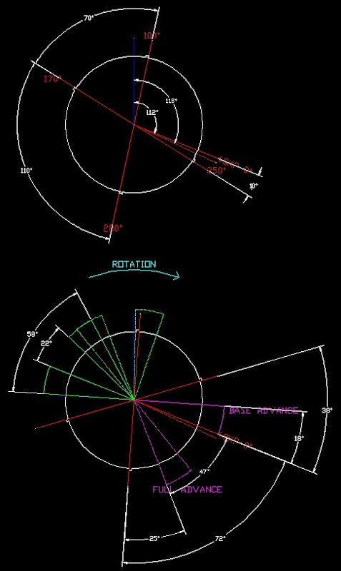
(Apologies for the image quality).
The upper image depicts the crank wheel alone at TDC.
The lower depicts both the crank and camshaft timing overlaid (phase is correct with respect to crank vs. cam, however, the timing is 180* between the two cam identities only to represent complete advance phasing) .
Last edited by kcbhiw; 02-04-2010 at 12:04 AM.
Reply
0
0
02-04-2010, 01:20 AM
#72
Elite Member
Thread Starter
Join Date: Jul 2005
Posts: 6,420
Total Cats: 84
I get it now. The below waveform is full retard.
At full advance, the lower (cam) waveform moves left by 47*.
The result is that the first cam rising edge below, will move left and be only 3* to the right of the 2nd crank pulse shown. The falling edge will cross over the crank pulse on its left when it goes from full retard to advance. The 20* number will grow to 67*. However the rising edges of the cam and crank never meet regardless of VVT phase angle.
Any ECU should be set up to read ONLY the rising edges of the crank and the cam.

Here are the full retard and advance waveforms.
Full advance: (only pay attention to the crank rising edges, the crank falling edges have "gone bonkers" during cranking as I've noted elsewhere"

Another fulll Retard:

At full advance, the lower (cam) waveform moves left by 47*.
The result is that the first cam rising edge below, will move left and be only 3* to the right of the 2nd crank pulse shown. The falling edge will cross over the crank pulse on its left when it goes from full retard to advance. The 20* number will grow to 67*. However the rising edges of the cam and crank never meet regardless of VVT phase angle.
Any ECU should be set up to read ONLY the rising edges of the crank and the cam.
Here are the full retard and advance waveforms.
Full advance: (only pay attention to the crank rising edges, the crank falling edges have "gone bonkers" during cranking as I've noted elsewhere"
Another fulll Retard:
Last edited by JasonC SBB; 02-05-2010 at 02:13 AM.
Reply
0
0
02-06-2010, 01:22 PM
#73
Elite Member
Thread Starter
Join Date: Jul 2005
Posts: 6,420
Total Cats: 84
Video of spool valve operation
YouTube - OCV1.avi
Solenoid is 7.5 ohms, 45 mH.
This video was taken while the voltage being applied was varied from 0 to around 8V and back. At 0V the plunger sits to the left due to spring force (towards the O-ring). As voltage is increased, the plunger moves to the right.
The piston begins to move at 300 mA. It reaches the end at 900 mA. Halfway there is a "dead zone" where the 2 oil entrance slots are blocked, at 520 to 540 mA. In this position the cam phase will be locked. The stiction is worth about 20 mA - i.e. there is 20 mA of deadband.
This type of valve is also called a "spool valve". Its function is to steer oil flow/pressure between 2 outlets. The plunger will cause oil to flow to outlet A, or outlet B, or to a combination of both, depending on plunger position.
One side of the valve has 2 large slots (start of video). I believe oil enters here. These slots face up when the valve is installed. When I turn it over you will see 3 large slots. I believe oil exits there. When the plunger is to the left, oil flows towards the retard chamber of the VVT actuator. When the plunger is to the right, oil flows to the advance chamber of the VVT actuator.
Reply
0
0
02-06-2010, 01:44 PM
#74
Elite Member
Thread Starter
Join Date: Jul 2005
Posts: 6,420
Total Cats: 84
Valve will be at rest (retard) position at 300 mA - ~16% duty cycle at 14V
Valve will be at endstop (advance) at 900 mA - ~48% duty cycle at 14V
Valve is centered in "lock" position at 530 mA - ~28% duty cycle at 14V
Valve will be at endstop (advance) at 900 mA - ~48% duty cycle at 14V
Valve is centered in "lock" position at 530 mA - ~28% duty cycle at 14V
Last edited by JasonC SBB; 02-13-2010 at 11:22 PM.
Reply
0
0
02-06-2010, 02:54 PM
#75
2 Props,3 Dildos,& 1 Cat


iTrader: (8)
Join Date: Jun 2005
Location: Fake Virginia
Posts: 19,338
Total Cats: 573
are those numbers good for dumping straight into the adaptronic software? it's got "min" "default" and "max".
or presumably a slightly wider range to account for other system voltages?
or presumably a slightly wider range to account for other system voltages?
Reply
0
0
02-08-2010, 02:00 AM
#78
Elite Member
Thread Starter
Join Date: Jul 2005
Posts: 6,420
Total Cats: 84
There have been reports of valve seat damage, possibly from rapid advance on top of RPM causing hard landings of the valve onto the seat.
Here is a possible solution.
Place a 10~12 ohm, 10W resistor in series with the solenoid. This will reduce the distance the solenoid moves in the advance position, thus reducing the *rate* of advance.
Here is a possible solution.
Place a 10~12 ohm, 10W resistor in series with the solenoid. This will reduce the distance the solenoid moves in the advance position, thus reducing the *rate* of advance.
Reply
0
0
02-13-2010, 10:59 PM
#79
With the new routine in place, I'm seeing a lot of steady state between the 40-45% DC (@ 480 Hz) range. However, at this point, I haven't compensated for voltage, but it shouldn't matter much for this reference. Response seems to taper off above 70% DC.
Reply
0
0
02-13-2010, 11:20 PM
#80
Elite Member
Thread Starter
Join Date: Jul 2005
Posts: 6,420
Total Cats: 84
Hmm. The most recent numbers I posted from pulling the valve and testing it, agree with my early in-car-engine-running observations - "lock" is around 0.52A:
https://www.miataturbo.net/forum/t27030/#post318935
https://www.miataturbo.net/forum/t27030/#post318935
Reply
0
0


