
[Solved] FAB9 CoP spark blowout
 07-01-2014, 05:47 PM
#41
Elite Member

Join Date: Jul 2005
Posts: 6,420
Total Cats: 84
It is hard to believe that the driver inputs are designed such that there is a significant difference between 4.2V and 5V. 3V and 5V, sure, but not 4.2 to 5V.
Was that guy with the 4.2V signal having trouble?
Was that guy with the 4.2V signal having trouble?

Reply
 0
0

0
07-01-2014, 07:19 PM
#42

I have a harness that I've been working on that should solve this problem if I can reliably regulate a 5V+ supply (a 5v regulator isn't quick enough to keep up). I can't exactly do the testing on a breadboard because of the amperage fluctuations of an alternator but I might find a combo of resistors that give me around 7v on a running Miata and then use a solid state relay to forward it. Maybe you have some insight?
Reply
0
0
07-01-2014, 07:28 PM
#43

Why a regulator on a signal in a digital system?
An option would be a simple 5v digital buffer if the single driver in the MS doesn't have the juice to run wasted spark.
If you plan on making it standalone in the engine bay then a 5v regulator (off the 12v system) is the ticket to power your buffer solution.
An option would be a simple 5v digital buffer if the single driver in the MS doesn't have the juice to run wasted spark.
If you plan on making it standalone in the engine bay then a 5v regulator (off the 12v system) is the ticket to power your buffer solution.
Reply
0
0
07-01-2014, 09:08 PM
#44
Elite Member
Join Date: Jul 2005
Posts: 6,420
Total Cats: 84
The input to the CDI system is a digital signal. It does not affect the quality nor strength of the spark. It's either spark or no spark.
That 4.2 V thing is not the cause of weak spark issues.
I do analog electronics design for a living.
That 4.2 V thing is not the cause of weak spark issues.
I do analog electronics design for a living.
Reply
0
0
07-01-2014, 09:33 PM
#45
 .
.If not the signal voltage, can you explain what else might be causing the problem with Megasquirt systems running wasted spark? Why are some customers and myself able to run much higher boost (27-28 before break up) on exactly the same systems.
Reply
0
0
07-02-2014, 10:08 AM
#47
Junior Member

Join Date: Sep 2011
Location: finger lakes NY
Posts: 433
Total Cats: 17
Mr (Ms?) FAB9, I appreciate your efforts to find a solution, but I'm with Jason in that I don't think you're going down the right road.
What information can you provide on the COPS's? If I understand what they really require then I can help find a good robust solution.
What information can you provide on the COPS's? If I understand what they really require then I can help find a good robust solution.
Reply
1
1
07-02-2014, 10:37 AM
#48
Information I do have:
- 3-4 guys running MS have had trouble running them on wasted spark.
- One of them happened to scope the signal while the car was running and saw a max of 4.2v and the components used in the ignition module state a minimal of 5v is required.
- Some MS customers don't have the issue at all. (maybe they are running sequential) Some customers with piggy back systems or timing cards have the identical issue.
- I've also discovered that increasing the signal voltage solved the problem and that if increased too much it will destroy the ignition module in a short period of time.
- It's not a matter of the components ability to produce a strong spark. My personal car ran the exact same kit I ship to customers at very high boost levels for the past 4-5 months. I'm using an AEM EMS4, sequential.
I've been busy catching up with back-ordered kits (over 300 kits have shipped this year) so unfortunately I don't have time to look deeper into this, I'm also not an electrical engineer. I have a local GM electrical engineer that was giving me advice but I have the feeling this isn't his area of expertise.
Cheers,
Bryan
Reply
0
0
07-02-2014, 12:39 PM
#51
Senior Member
Thread Starter
iTrader: (1)

Join Date: Jan 2012
Location: Tampa, FL
Posts: 754
Total Cats: 19
Trying to give him the general jist of what's going on.
I know Matt has an account here, it'd be more efficient if you guys could talk.
Reply
I know Matt has an account here, it'd be more efficient if you guys could talk.
FAB9: "5v and our module want's allofit. However when running wasted spark you're splitting that current between 2 channels and that's where the problem comes in. "
Abd that's where the pull up resistor comes in, they are saying that swapping the 1kohm for a 100ohm would help.
This is the video of what happens with the COPs:
Turbo Miata CoP problem - YouTube
Sent from Yahoo Mail on Android
Abd that's where the pull up resistor comes in, they are saying that swapping the 1kohm for a 100ohm would help.
This is the video of what happens with the COPs:
Turbo Miata CoP problem - YouTube
Sent from Yahoo Mail on Android
Except the MSPNP doesn't use a 1K resistor; the inline resistance is 100 ohms. Do they have a current spec for what their module needs?
Thanks,
Matt Cramer
DIYAutoTune.com
Thanks,
Matt Cramer
DIYAutoTune.com
Reply
0
0
07-02-2014, 05:42 PM
#53
Senior Member
Thread Starter
iTrader: (1)
Join Date: Jan 2012
Location: Tampa, FL
Posts: 754
Total Cats: 19
You posted what you think the output is. Which turns out is wrong. It's inline 100 ohms.-
So, what's your point again?
_________

Now watch what happens.
So, what's your point again?
Now watch what happens.
Last edited by Impuls; 07-03-2014 at 11:51 AM. Reason: Added hidden gem.
Reply
0
0
07-03-2014, 06:12 AM
#54
Junior Member

Join Date: Nov 2012
Location: Netherlands, Europe
Posts: 204
Total Cats: 29
To FAB9: I am also an electrical engineer and I am also interested in this problem. Do you have any datasheets or other information/data from the manufacturer of the CDI module ? You can PM if you do not want to get this into the public.
Best way to determine how to control the CDI would be to tear one down and fully understand its workings. CDI is not some very complicated technology so I would quickly understand its workings and I would be able to do some measurements when I have a module on my desk.
I was thinking of buying one of these COP kits, but I am a bit reluctant to buy when I do not know how to control it in the most appropriate way.
Reply
0
0
07-03-2014, 07:26 AM
#55
Boost Czar


iTrader: (62)
Join Date: May 2005
Location: Chantilly, VA
Posts: 79,493
Total Cats: 4,080
The inline resistor is just current limiting. A 100ohm resistor on a 5V output is limiting the current to .05A (5v/.05A = 100r). The output will still be 5v.
I was pointing out the difference between the DIYPNP, MSPNP2 & MS3x vs. the most MS1 and MSPNP1 units is that former is normally low and the latter is normally high, but both ultimately output a digital 5v signal.
When I suggested the MS in question had a 1K resistor, I was referring to a MSPNP1 built on the v3.57 board that has a built-in 1K resistor pull-up. If you look here on page 7, you can clearly see R58 and R60 for yourself.
One needs to be very specific when asking questions because there are many varieties of MS out there.
I posted the schematic of the 1K pull-up on the v3.57 board. That was the resistor I was talking about. The MSPNP1 was built using the v3.57 mainboard, the MSPNP2 uses the micosquirt module. There is a big difference between the two, especially in regards to the spark output.
The MS, in all its varieties, has no issues firing the stock coils, or toyota coils, or almost any other ignition setup people have used (like GM coils). The only ignition setup that people seem to be having issue with is this FAB setup. Please note: I'm not saying anything bad about the product; just saying.
I suggested changing the 1K resistor because back in 06 or so, when we were building MS1 units, we started switch from a 1K pull-up to a 100-300ohm pull-up to 5v because it was suggested it would help provide a cleaner spark signal. It's been so long I don't quite remember the reasoning, but it could be part of the problem here. Here's a thread that I talked about it back in 2009.
I also remember someone having issues with the ms expander board and trying to run wasted spark off it or something. I'd have to go back and find it. Could be somewhat related; like it couldn't fire two coils from one output. I just can't quite remember and I'd have to go back and find it. I think they changed the firmware after that to give the option for wasted COP so each coil fired from its own circuit but in a wasted firing order.
But like others have suggested, the "power" of the signal from the ECU shouldn't matter. It's not directly responsible for providing power to the coils. All it's doing is toggling from 0v to 5v and when it does, the coil knows when it should release its own charge to the coil. It just needs to see that switch from low to high, it doesn't matter how many amps is passing through, because it's not using it. That's why it's called a trigger. Like when firing a gun, it doesn't matter how hard, or lightly, you pull the trigger, all that matters is that you pull it.
Keep in mind: I am not an electrical engineer, engineer, or electrical. some might describe me as magical, but I also describe electricity as black magic.
Now don't ever question me again.
Edit: here's a thread where it was discussed how to convert the MS output to trigger 12v safely, and more about current limiting resistors. I think it also speaks to as why people should listen to Joe P on this subject. And post #17 talks about the 1K to 100ohm pull-up switcheroo. I'm still leaning in this direction.
Last edited by Braineack; 07-03-2014 at 08:42 AM.
Reply
1
1
 07-03-2014, 09:37 AM
#57
Haha. I knew that response was coming. I appreciate the input, Scott.
I still believe it's absolutely related to the signal quality. Even though this is a "trigger" signal these components still produce some form of resistance. Apparently enough resistance to make a difference to the signal when driving two channels at once.
There IS a reason this is a powerhouse setup on an AEM and not a functioning properly on some of these MS systems and I can't imagine there are any other factors involved than the trigger signal, or is this bad logic? It must be very close to the threshold because it's not all MS guys that have this problem.
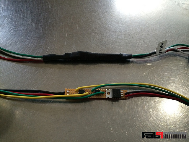
Based on a previous suggestion, I'm going to attempt to build a signal buffer - any thoughts on this?
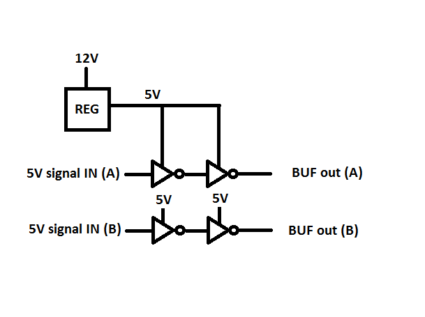
With suggestions on which components to use, I should be able to build this into the harness. I'm also going to attempt to revamp the harness with the solid state relays.
I still believe it's absolutely related to the signal quality. Even though this is a "trigger" signal these components still produce some form of resistance. Apparently enough resistance to make a difference to the signal when driving two channels at once.
There IS a reason this is a powerhouse setup on an AEM and not a functioning properly on some of these MS systems and I can't imagine there are any other factors involved than the trigger signal, or is this bad logic? It must be very close to the threshold because it's not all MS guys that have this problem.
Based on a previous suggestion, I'm going to attempt to build a signal buffer - any thoughts on this?
With suggestions on which components to use, I should be able to build this into the harness. I'm also going to attempt to revamp the harness with the solid state relays.
Reply
0
0
07-03-2014, 09:41 AM
#58
Boost Czar
iTrader: (62)
Join Date: May 2005
Location: Chantilly, VA
Posts: 79,493
Total Cats: 4,080
Joe talks about how the quality of the rising edge improved when the pull-up resistor was swapped out in post #17.
if the issue is limited to older MSPNP1 units, then this is probably the solution. and you could add in a second 270-330 pull-up resistor on the output very easily--you shouldn't even have to remove the stamped 1Ks.
Reply
0
0
07-03-2014, 10:40 AM
#59
Junior Member
Join Date: Sep 2011
Location: finger lakes NY
Posts: 433
Total Cats: 17
All digital circuits are analog if you look closely enough. More to the point, not all digital inputs work identically. Obviously there can be different voltage requirements, but the input impedance (current draw) can vary hugely. That's why I want to measure one of these coils; then we'll know.
There are some measurements of different pencil coils around the web. Some show that the trigger pin can draw more than 10 mA while high. Put two in parallel and that's over 20 mA that we're asking the CPU pin to supply and it might not be happy doing it.
Changing a pullup resistor to something smaller typically helps with a so-called open collector circuit. This is one where a transistor acts like an on-off switch connecting an output to ground. Either it connects to ground (pulls down) or it just lets go. The pull up resistor is then left with the job of bringing the output high. This works fine if significant current is drawn only when in the low state. But there can still be some current drawn in the high state. A large pull up resistor limits this current. A smaller one improves rising edges and possibly increases the voltage at the output.
In the case where an output pulls up and down actively (most IC's) then pull up and pull down resistors are usually just for protection during power up.
As Scott said, the 100 ohm series resistor on the Microsquirt module is there just to protect the CPU if there's a short circuit. But if whatever is being driven requires more than a few milliamps then that resistor can reduce performance. The above mentioned 20 mA will result in a 2 volt drop across the resistor; the output will be only 3 volts instead of the expected 5!
Personally, I think it's an abomination to drive anything off-board directly from CPU pins. (I am an EE and design embedded systems for a living.)
Reply
0
0
07-03-2014, 10:55 AM
#60
Supporting Vendor

iTrader: (33)
Join Date: Jul 2006
Location: atlanta-ish
Posts: 12,659
Total Cats: 134
Why a regulator on a signal in a digital system?
An option would be a simple 5v digital buffer if the single driver in the MS doesn't have the juice to run wasted spark.
If you plan on making it standalone in the engine bay then a 5v regulator (off the 12v system) is the ticket to power your buffer solution.
An option would be a simple 5v digital buffer if the single driver in the MS doesn't have the juice to run wasted spark.
If you plan on making it standalone in the engine bay then a 5v regulator (off the 12v system) is the ticket to power your buffer solution.
This will trigger (2) BIP373 drivers, (2) VAG logic coils, or (2) IGN-1A coils.
Spark outputs C and D are accessible from the DB26 connector. They are set up for "wasted cop" by default, where A and D are triggered together and B and C are triggered together. These outputs are also rated at 220ma, or 440ma per channel. If you truly feel that the standard spark outputs do not provide enough current for your wasted setup, then use the C and D outputs as well.
http://www.megasquirtpnp.com/docs/ms...r=13&isModel=2

Reply
0
0


