
The Definitive "VVT swap into 90-97 chassis" Megathread.
 08-17-2014, 09:47 PM
#1
Former Vendor

Thread Starter
iTrader: (31)

Join Date: Nov 2006
Location: Sunnyvale, CA
Posts: 15,442
Total Cats: 2,099
The Definitive 1990-1997 VVT Swap Megathread.
I've made several posts on this topic, but I've never consolidated all of the information into once place until now. This thread will outline all of the mechanical and wiring tweaks necessary to install a 2001+ engine in a 1990-1997 chassis. This method relies mostly on OEM 1990-1997 wiring, and assumes you will be using a standalone ECU (either an AEM or a Megasquirt of some variety).
There are other ways to complete the same task, but this post will outline the methods I've used successfully. I believe that this is the easiest way to complete this swap with the least cost and headaches incurred.
In some places, I have added info that is 99-00 specific, but this thread is largely VVT-specific. If you are doing a 99-00 BP4W swap, you'll need to fill in the gaps yourself.
VVT = Variable Valve Timing
VICS = Variable Intake Control System
VTCS = Variable Throttle Control System
EUDM = European Domestic Market
TPS = Throttle Position Sensor
IAC = Idle Air Control
CAS = Cam Angle Sensor (refers specifically to the 90-97 sensor)
Motor mounts, transmission, clutch, flywheel, starter motor
Any 1994-2005 motor mount will bolt up to the 2001-2005 block. The 2001-2005 engines used a unique 4-hole mount, but any 94-05 3-hole mount will work in place of these. All 1.8 mounts (94-05) will bolt into the 90-97 sub-frame.
All 5 and 6-speed 90-05 transmissions will bolt up to the 99-05 block. You can use any clutch (1.6 or 1.8) as long as you use a matching flywheel (1.6 clutch with 1.6 flywheel, 1.8 clutch with 1.8 flywheel).
The starter motors are functionally identical. The NB starter is lighter, so if you have the choice, use it.
Alternator and pulleys
Use a 1994-1997 alternator and pulley. The 1.6 alternator has a different shaft diameter, so a pulley swap is not possible - the entire alternator must be swapped. It may be possible to use the 99-05 ECU with wiring changes and an ECU with alternator control, but few/no PnP ECUs for 1990-1997s will have this feature, so it's easiest to simply use a 94-97 alternator with onboard control. For 90-93 cars, you will need to enlarge the hole in your factory alternator wire ring terminal, or install a new, larger ring terminal to match the larger 94-97 alternator lug.
Intake manifold, throttle body, and throttle cable
Use any 1999-2005 intake manifold (VICS, VCTS, or EUDM Squaretop). There are three OEM intake manifold options. The 99-00 "VICS" manifold will produce the most low-end torque (assuming you are controlling the VICS butterflies). The 01-05 "VTCS" manifold is the most common and the cheapest, but it makes slightly less power than the other two options and requires very slight modification to clear the 99-00 fuel rail. The 02-05 JDM/EUDM "Squaretop" manifold was available overseas and makes more power than either US-market intake manifold, but slightly less mid-range torque than the 99-00 VICS manifold. The 1994-1997 intake manifold will bolt up, but the ports on the 99-05 heads are significantly higher and the 94-97 IM ports are misaligned by 3/4". All three intake manifolds are EGR compatible. The EUDM manifolds came with an EGR valve in Europe, while Japanese market cars were shipped with block-off plates on those ports.
All three intake manifolds have the same throttle body location. Any 1994-2005 throttle body can be used, but the 99-05 TB is more desirable for its internal idle valve routing, which makes plumbing for custom 2.5" cold air intakes or intercooler piping much simpler. Using the 99-05 throttle body will require that you change the TPS and IAC valve pigtails, but this is a fairly simple modification. The 1990-1993 throttle body cannot be used on the 99-05 manifold without an adapter, and you lose the benefits of the linear TPS on all 94-05 throttle bodies.
Use a 1999-2005 throttle cable. It will bolt directly into the NA chassis and fit perfectly with the NB engine. The NA cable is too long.
Exhaust manifold and exhaust
Any header from 1994-2005 will bolt up to the head. If you are using a 1994-1997 header, you will need to delete the EGR tube and EGR valve, but you will be able to use a cat and catback exhaust from a 1994-1997 (the exhaust hangar locations are the same for 90-97). Using a 1999-2005 header will allow you to retain the EGR tube, but you will need to have a custom cat pipe built to jump from the 99-05 header flange to your 90-97 catback (you cannot use an NB catback without changing several of the exhaust hangars). If you use a 99-05 header to retain EGR, the 2001+ headers flow much better and are significantly more desirable.
Fuel system:
Use a 1999-2000 fuel rail and a 1990-1993 USDM fuel pressure regulator installed upside down with the fuel outlet bent straight to clear the intake manifold. No other combination of USDM parts will work. The 90-93 fuel rails are too short, the 94-97 rails have incorrect mounting tabs, and the 01-05 rail places the fuel pressure regulator in a spot which interferes with the cylinder head. The 94-97 FPR places the pressure reference in a spot which interferes with the cylinder head and the 99-05 regulators do not have a return line.
In Europe/Japan, a return-style 1.8L NB was available, and the FPR from that car will bolt up to the USDM 1999-2000 fuel rail as well. No modifications are needed to install this part, and the return line will face down. The part number is BP5B-13-280. This is a 43.5psi vacuum-referenced regulator (1:1), just like the USDM 90-97 regulators.
You will need to retain one of the fuel injection fittings from the 01-05 fuel rail to use as an adapter on the 99-00 fuel rail. I prefer to use a 90* adapter instead of a straight adapter to aid fuel line routing around the alternator. Do not simply slip a fuel hose over the end of the 99-00 fuel rail - it will not stay in place. Use 5/16" fuel hose to run from the feed line to the 90* fuel injection adapter and into the fuel rail. For the return, install the 90-93 FPR upside down in place of the OEM 99-00 fuel damper (fuel outlet facing up). Use 5/16" fuel line to run around the back of the intake manifold and into the return line on the chassis. The fuel pressure will be 43psi with a pressure reference, just like the 1990-1993 fuel system.
Alternatively, you can use an aftermarket fuel pressure regulator. The stock VVT fuel rail can be used if the factory fuel damper is replaced with an adapter and used in conjunction with an aftermarket fuel pressure regulator.
This adapter will fit and allows you to use the OEM VVT fuel rail: http://www.trackspeedengineering.com...r-adapter.html
Coils:
Use the 2001-2005 coils and wires. The VVT oil feed line interferes with the 1990-2000 coil mounting location. The 01-05 coils are fairly reliable and easy to wire up.
Wiring:
CAS:
You must use the NB cam and crank angle sensors if you want VVT control. There is no way to control the VVT if you use an NA-style CAS driven from the exhaust camshaft.
The OEM 1990-1997 CAS has 4 wires. One wire is +12v, one wire is a sensor ground, and there is a signal wire for the crank position and a signal wire for the cam position. You will need to cut the factory plug off and extend the +12v and ground wires to each of the NB sensors. The cam signal wire will get routed to the camshaft sensor on the top of the valve cover, and the crank signal wire will get routed to the crankshaft sensor located near the harmonic damper. This will bring the appropriate cam and crankshaft patterns along the OEM harness into the ECU, and all of the other changes necessary will happen in the firmware/software of your ECU.
12v (extend 90-97 wire to both 99-05 sensors):
90-97: White/Red
99-05: White/Red
Cam (extend to Cam sensor only):
90-97: yellow/blue
99-00: grey/blue
01-05: grey/blue
Crank (extend to Crank sensor only)
90-97: white
99-00 grey/red
01-05 violet/white
Ground (extend to both 99-05 sensors)
90-97: black/light green
99-05: black/blue
IAC Valve:
If you are swapping to the 99-05 throttle body to upgrade to the internally routed IAC valve, you will need to swap the pigtails for the TPS and IAC wires. The IAC valve wiring is not sensitive to polarity, so you can simply swap the pigtail without worrying about which wire goes where.
TPS:
The 90-93 manual chassis did not originally come with a 0-5v variable TPS. To use a 94-05 0-5v throttle position sensor in a 90-93 chassis, consult with your ECU supplier to confirm the wiring changes that are necessary.
The 1994-1997 chassis did come with a 0-5v variable TPS. It is a standard 3-wire TPS with an additional fourth wire (red) which serves as a wide-open switch. Your standalone ECU will likely not use this fourth wire, so if you are changing the pigtail to a 99-05 style, simply heat-shrink over this unused wire. If you are using your 94-97 throttle body, there are no wiring changes necessary. If you are using the 99-05 sensor, wiring colors are listed below:
5v Reference:
94-97: Light Green/White
99-05: Light Green/Red
Signal:
94-97: Red/Black
99-05: Green/Black
Ground:
94-97: Black/Blue
99-05: Black/Red
VVT:
The VVT solenoid is a 2-wire PWM solenoid, just like an EBC valve. There is no polarity on the wires. Connect one wire to +12v (the injector harness is very close and has plenty of extra current room on its fuse) and the other wire directly to your ECU's VVT control pin.
Coils
The wiring modifications for the coils are chassis-specific.
1990-1993:
You will need to delete the ignitor first. The 01-05 coils have on-board ignitors. Connect the wires as follows:
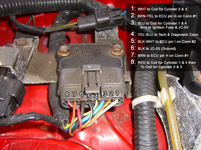
Route 1 (white) to 2 (brown/yellow) (trigger for cyl 1/4, the text in the pic above is wrong, see post #156)
Route 7 (brown) to 8 (red) (trigger for cyl 2/3, text in pic above is wrong, see post #156)
Route 4 (yellow/blue) to 5 (black/white) (connects ECU directly to tachometer at gauge cluster)
Terminate 3 (blue) (unused +12v)
Terminate 6 (black) (unused ground)
At the 90-93 coil connector, there are three wires (+12v and two triggers, no ground). Connect as follows:
12v:
90-93: Blue
99-05: Black/White
Trigger cyl 1/4:
90-93: white
99-00: brown/yellow
01-05: brown/white
Trigger cyl 2/3:
90-93: red
99-00: brown
01-05: black/yellow
Ground:
90-93: none
99-05: black (ground to intake manifold)
The 01-05 coils have no provisions for a tachometer output. The MS Labs MS3 Basic, AEM Series 1 (30-1710), AEM EMS-4 (30-6905), MSPNP2, MS3-Pro, and all 94+ MSPNP1s have a tachometer driver which will run the factory tach in lieu of the factory coils. For 90-93 MSPNP1 owners, you will need an aftermarket tachometer driver, which can either be added to your ECU or purchased and wired separately. See posts 44 and 62 for more details.
1994-1997 coils:
+12v:
94-97: Blue
99-05: Black/White
trigger cyl 1/4:
94-00: brown/yellow
01-05: brown/white
trigger cyl 2/3:
94-00: brown
01-05: black/yellow
ground:
94-05: black
Injectors (90-93 only)
Most people elect to switch to sequential fuel while doing this swap. The factory 1990-1993 cars (except for California-emissions 1993 cars) have fuel injectors wired in pairs (1/3 and 2/4). I typically elect to run new trigger wires for injectors #3 and #4 and leave the OEM trigger wires in place for cylinders #1 and #2. Simply cut the trigger wires (Yellow and Yellow/Black) at the #3 and #4 injector pigtails, heat-shrink the loose ends on the harness side, and attach/route two new wires directly from your ECU to the trigger wires for injectors #3 and #4. Terminate all loose wire ends.
Injectors ('93 California emissions and all 94-97):
Use your factory 94-97 injector harness. No modifications are necessary.
CLT sensors
The 90-93 cars have two coolant temp sensors and a thermo-switch. The two-wire sensor on the back of the head is the sensor that provides the ECU. The one-wire sensor on the back of the head provides signal to the gauge cluster. The one-wire switch on the front of the engine switches the fans on and off. The 1994-1997 cars have the same two sensors on the back of the head, but the OEM ECU controls the fans instead of a separate thermo-switch.
Install your 1990-1997 2-wire ECU coolant temp sensor and your one-wire gauge coolant temp sensor in the 2001-2005 engine. This will allow you to retain your OEM CLT sensor pigtails. The 01-05 engines have a small plug in the hole used by the one-wire gauge sender - simply remove the plug and install the sender in the 01-05 engine. The front thermo-switch (90-93) is no longer necessary, as your ECU will control the fans.

I've made several posts on this topic, but I've never consolidated all of the information into once place until now. This thread will outline all of the mechanical and wiring tweaks necessary to install a 2001+ engine in a 1990-1997 chassis. This method relies mostly on OEM 1990-1997 wiring, and assumes you will be using a standalone ECU (either an AEM or a Megasquirt of some variety).
There are other ways to complete the same task, but this post will outline the methods I've used successfully. I believe that this is the easiest way to complete this swap with the least cost and headaches incurred.
In some places, I have added info that is 99-00 specific, but this thread is largely VVT-specific. If you are doing a 99-00 BP4W swap, you'll need to fill in the gaps yourself.
VVT = Variable Valve Timing
VICS = Variable Intake Control System
VTCS = Variable Throttle Control System
EUDM = European Domestic Market
TPS = Throttle Position Sensor
IAC = Idle Air Control
CAS = Cam Angle Sensor (refers specifically to the 90-97 sensor)
Motor mounts, transmission, clutch, flywheel, starter motor
Any 1994-2005 motor mount will bolt up to the 2001-2005 block. The 2001-2005 engines used a unique 4-hole mount, but any 94-05 3-hole mount will work in place of these. All 1.8 mounts (94-05) will bolt into the 90-97 sub-frame.
All 5 and 6-speed 90-05 transmissions will bolt up to the 99-05 block. You can use any clutch (1.6 or 1.8) as long as you use a matching flywheel (1.6 clutch with 1.6 flywheel, 1.8 clutch with 1.8 flywheel).
The starter motors are functionally identical. The NB starter is lighter, so if you have the choice, use it.
Alternator and pulleys
Use a 1994-1997 alternator and pulley. The 1.6 alternator has a different shaft diameter, so a pulley swap is not possible - the entire alternator must be swapped. It may be possible to use the 99-05 ECU with wiring changes and an ECU with alternator control, but few/no PnP ECUs for 1990-1997s will have this feature, so it's easiest to simply use a 94-97 alternator with onboard control. For 90-93 cars, you will need to enlarge the hole in your factory alternator wire ring terminal, or install a new, larger ring terminal to match the larger 94-97 alternator lug.
Intake manifold, throttle body, and throttle cable
Use any 1999-2005 intake manifold (VICS, VCTS, or EUDM Squaretop). There are three OEM intake manifold options. The 99-00 "VICS" manifold will produce the most low-end torque (assuming you are controlling the VICS butterflies). The 01-05 "VTCS" manifold is the most common and the cheapest, but it makes slightly less power than the other two options and requires very slight modification to clear the 99-00 fuel rail. The 02-05 JDM/EUDM "Squaretop" manifold was available overseas and makes more power than either US-market intake manifold, but slightly less mid-range torque than the 99-00 VICS manifold. The 1994-1997 intake manifold will bolt up, but the ports on the 99-05 heads are significantly higher and the 94-97 IM ports are misaligned by 3/4". All three intake manifolds are EGR compatible. The EUDM manifolds came with an EGR valve in Europe, while Japanese market cars were shipped with block-off plates on those ports.
All three intake manifolds have the same throttle body location. Any 1994-2005 throttle body can be used, but the 99-05 TB is more desirable for its internal idle valve routing, which makes plumbing for custom 2.5" cold air intakes or intercooler piping much simpler. Using the 99-05 throttle body will require that you change the TPS and IAC valve pigtails, but this is a fairly simple modification. The 1990-1993 throttle body cannot be used on the 99-05 manifold without an adapter, and you lose the benefits of the linear TPS on all 94-05 throttle bodies.
Use a 1999-2005 throttle cable. It will bolt directly into the NA chassis and fit perfectly with the NB engine. The NA cable is too long.
Exhaust manifold and exhaust
Any header from 1994-2005 will bolt up to the head. If you are using a 1994-1997 header, you will need to delete the EGR tube and EGR valve, but you will be able to use a cat and catback exhaust from a 1994-1997 (the exhaust hangar locations are the same for 90-97). Using a 1999-2005 header will allow you to retain the EGR tube, but you will need to have a custom cat pipe built to jump from the 99-05 header flange to your 90-97 catback (you cannot use an NB catback without changing several of the exhaust hangars). If you use a 99-05 header to retain EGR, the 2001+ headers flow much better and are significantly more desirable.
Fuel system:
Use a 1999-2000 fuel rail and a 1990-1993 USDM fuel pressure regulator installed upside down with the fuel outlet bent straight to clear the intake manifold. No other combination of USDM parts will work. The 90-93 fuel rails are too short, the 94-97 rails have incorrect mounting tabs, and the 01-05 rail places the fuel pressure regulator in a spot which interferes with the cylinder head. The 94-97 FPR places the pressure reference in a spot which interferes with the cylinder head and the 99-05 regulators do not have a return line.
In Europe/Japan, a return-style 1.8L NB was available, and the FPR from that car will bolt up to the USDM 1999-2000 fuel rail as well. No modifications are needed to install this part, and the return line will face down. The part number is BP5B-13-280. This is a 43.5psi vacuum-referenced regulator (1:1), just like the USDM 90-97 regulators.
You will need to retain one of the fuel injection fittings from the 01-05 fuel rail to use as an adapter on the 99-00 fuel rail. I prefer to use a 90* adapter instead of a straight adapter to aid fuel line routing around the alternator. Do not simply slip a fuel hose over the end of the 99-00 fuel rail - it will not stay in place. Use 5/16" fuel hose to run from the feed line to the 90* fuel injection adapter and into the fuel rail. For the return, install the 90-93 FPR upside down in place of the OEM 99-00 fuel damper (fuel outlet facing up). Use 5/16" fuel line to run around the back of the intake manifold and into the return line on the chassis. The fuel pressure will be 43psi with a pressure reference, just like the 1990-1993 fuel system.
Alternatively, you can use an aftermarket fuel pressure regulator. The stock VVT fuel rail can be used if the factory fuel damper is replaced with an adapter and used in conjunction with an aftermarket fuel pressure regulator.
This adapter will fit and allows you to use the OEM VVT fuel rail: http://www.trackspeedengineering.com...r-adapter.html
Coils:
Use the 2001-2005 coils and wires. The VVT oil feed line interferes with the 1990-2000 coil mounting location. The 01-05 coils are fairly reliable and easy to wire up.
Wiring:
CAS:
You must use the NB cam and crank angle sensors if you want VVT control. There is no way to control the VVT if you use an NA-style CAS driven from the exhaust camshaft.
The OEM 1990-1997 CAS has 4 wires. One wire is +12v, one wire is a sensor ground, and there is a signal wire for the crank position and a signal wire for the cam position. You will need to cut the factory plug off and extend the +12v and ground wires to each of the NB sensors. The cam signal wire will get routed to the camshaft sensor on the top of the valve cover, and the crank signal wire will get routed to the crankshaft sensor located near the harmonic damper. This will bring the appropriate cam and crankshaft patterns along the OEM harness into the ECU, and all of the other changes necessary will happen in the firmware/software of your ECU.
12v (extend 90-97 wire to both 99-05 sensors):
90-97: White/Red
99-05: White/Red
Cam (extend to Cam sensor only):
90-97: yellow/blue
99-00: grey/blue
01-05: grey/blue
Crank (extend to Crank sensor only)
90-97: white
99-00 grey/red
01-05 violet/white
Ground (extend to both 99-05 sensors)
90-97: black/light green
99-05: black/blue
IAC Valve:
If you are swapping to the 99-05 throttle body to upgrade to the internally routed IAC valve, you will need to swap the pigtails for the TPS and IAC wires. The IAC valve wiring is not sensitive to polarity, so you can simply swap the pigtail without worrying about which wire goes where.
TPS:
The 90-93 manual chassis did not originally come with a 0-5v variable TPS. To use a 94-05 0-5v throttle position sensor in a 90-93 chassis, consult with your ECU supplier to confirm the wiring changes that are necessary.
The 1994-1997 chassis did come with a 0-5v variable TPS. It is a standard 3-wire TPS with an additional fourth wire (red) which serves as a wide-open switch. Your standalone ECU will likely not use this fourth wire, so if you are changing the pigtail to a 99-05 style, simply heat-shrink over this unused wire. If you are using your 94-97 throttle body, there are no wiring changes necessary. If you are using the 99-05 sensor, wiring colors are listed below:
5v Reference:
94-97: Light Green/White
99-05: Light Green/Red
Signal:
94-97: Red/Black
99-05: Green/Black
Ground:
94-97: Black/Blue
99-05: Black/Red
VVT:
The VVT solenoid is a 2-wire PWM solenoid, just like an EBC valve. There is no polarity on the wires. Connect one wire to +12v (the injector harness is very close and has plenty of extra current room on its fuse) and the other wire directly to your ECU's VVT control pin.
Coils
The wiring modifications for the coils are chassis-specific.
1990-1993:
You will need to delete the ignitor first. The 01-05 coils have on-board ignitors. Connect the wires as follows:
Route 1 (white) to 2 (brown/yellow) (trigger for cyl 1/4, the text in the pic above is wrong, see post #156)
Route 7 (brown) to 8 (red) (trigger for cyl 2/3, text in pic above is wrong, see post #156)
Route 4 (yellow/blue) to 5 (black/white) (connects ECU directly to tachometer at gauge cluster)
Terminate 3 (blue) (unused +12v)
Terminate 6 (black) (unused ground)
At the 90-93 coil connector, there are three wires (+12v and two triggers, no ground). Connect as follows:
12v:
90-93: Blue
99-05: Black/White
Trigger cyl 1/4:
90-93: white
99-00: brown/yellow
01-05: brown/white
Trigger cyl 2/3:
90-93: red
99-00: brown
01-05: black/yellow
Ground:
90-93: none
99-05: black (ground to intake manifold)
The 01-05 coils have no provisions for a tachometer output. The MS Labs MS3 Basic, AEM Series 1 (30-1710), AEM EMS-4 (30-6905), MSPNP2, MS3-Pro, and all 94+ MSPNP1s have a tachometer driver which will run the factory tach in lieu of the factory coils. For 90-93 MSPNP1 owners, you will need an aftermarket tachometer driver, which can either be added to your ECU or purchased and wired separately. See posts 44 and 62 for more details.
1994-1997 coils:
+12v:
94-97: Blue
99-05: Black/White
trigger cyl 1/4:
94-00: brown/yellow
01-05: brown/white
trigger cyl 2/3:
94-00: brown
01-05: black/yellow
ground:
94-05: black
Injectors (90-93 only)
Most people elect to switch to sequential fuel while doing this swap. The factory 1990-1993 cars (except for California-emissions 1993 cars) have fuel injectors wired in pairs (1/3 and 2/4). I typically elect to run new trigger wires for injectors #3 and #4 and leave the OEM trigger wires in place for cylinders #1 and #2. Simply cut the trigger wires (Yellow and Yellow/Black) at the #3 and #4 injector pigtails, heat-shrink the loose ends on the harness side, and attach/route two new wires directly from your ECU to the trigger wires for injectors #3 and #4. Terminate all loose wire ends.
Injectors ('93 California emissions and all 94-97):
Use your factory 94-97 injector harness. No modifications are necessary.
CLT sensors
The 90-93 cars have two coolant temp sensors and a thermo-switch. The two-wire sensor on the back of the head is the sensor that provides the ECU. The one-wire sensor on the back of the head provides signal to the gauge cluster. The one-wire switch on the front of the engine switches the fans on and off. The 1994-1997 cars have the same two sensors on the back of the head, but the OEM ECU controls the fans instead of a separate thermo-switch.
Install your 1990-1997 2-wire ECU coolant temp sensor and your one-wire gauge coolant temp sensor in the 2001-2005 engine. This will allow you to retain your OEM CLT sensor pigtails. The 01-05 engines have a small plug in the hole used by the one-wire gauge sender - simply remove the plug and install the sender in the 01-05 engine. The front thermo-switch (90-93) is no longer necessary, as your ECU will control the fans.
Last edited by Savington; 03-20-2018 at 01:18 PM. Reason: v1.09 3-20-18

Reply
 21
21

21
08-17-2014, 09:47 PM
#2
Former Vendor
Thread Starter
iTrader: (31)
Join Date: Nov 2006
Location: Sunnyvale, CA
Posts: 15,442
Total Cats: 2,099
First post reserved for update log.
8/17/14 v1.0
8/18/14: v1.01 (corrected 90-93 ignition trigger source and 01-05 coil pigtail wiring colors)
9/4/14: v1.02 (clarified CAS wiring requirements)
9/8/14: v1.03 (added 99-00 coil wiring for VVT into NB1 swaps, thanks Joyrider, and aftermarket tach info for 90-93 MSPNP1 owners, thanks Ben)
4/30/15: v1.04 (Fixed incorrect wire colors in 90-93 coil triggers)
12/17/16: v1.05 (added info on EUDM/JDM 1.8L return-style FPR)
12/28/17: v1.06 (corrected 94-97 coil wire trigger colors)
2/21/18: v1.07 (added info about aftermarket regulators in conjunction with OEM VVT fuel rail)
2/25/18: v1.08 (added note on 90-93 alternator ring terminal)
3/20/18: v1.09 (corrected 94-97 TPS 5vref wire color)
Last edited by Savington; 03-20-2018 at 01:18 PM.
Reply
0
0
08-18-2014, 09:52 AM
#3
Cpt. Slow
iTrader: (25)
Join Date: Oct 2005
Location: Oregon City, OR
Posts: 14,178
Total Cats: 1,129
Nice work Sav, this will help me a lot soon.
For comparison's sake, here are Keith's wiring instructions for the '01+ coils in a '90-'93
I think they're the same, but I haven't read through them both completely.
I did however follow the above instructions on a '90 and it worked perfectly. It does result in having ZERO tach. It'll require you to use a tach output pin on your standalone ECU (I'm assuming we all have one by now). And as another note, the gen1 MSPNPs did NOT have this output pin. Either send it to DIY for $75 and they'll solder in the necessary components, or buy your own bits and google how to do so. There is a drop down menu for a tacho output pin in tunerstudios, but the circuitry is not there.
For comparison's sake, here are Keith's wiring instructions for the '01+ coils in a '90-'93
Remove Mazda igniter & plug. We�ll be re-appropriating its wires & discarding the igniter in the steps below.
Clip the Mazda brown/yellow wire & the Mazda white wire. Crimp them together.
Clip the Mazda brown wire and the Mazda red wire. Crimp them together.
Clip the Mazda black/white wire & the Mazda yellow/blue wire. Crimp them together.
Clip the Mazda black wire & run it to the black wires at the 01-05 coil pigtails. This is ground.
Secure the leftover Mazda blue wire to prevent a short- it is 12V.
Now cut the 3-wire plug from the coil harness. Take the blue wire & run it to the black/white wires at the 01-05
coil pigtails. This is 12v.
The white wire runs the coil for cylinders 1&4. Connect it to the brown/white wire at the 1&4 01-05 coil.
The red wire runs cylinders 2&3. Connect it to the black/yellow wire at the 2&3 01-05 coil.
I did however follow the above instructions on a '90 and it worked perfectly. It does result in having ZERO tach. It'll require you to use a tach output pin on your standalone ECU (I'm assuming we all have one by now). And as another note, the gen1 MSPNPs did NOT have this output pin. Either send it to DIY for $75 and they'll solder in the necessary components, or buy your own bits and google how to do so. There is a drop down menu for a tacho output pin in tunerstudios, but the circuitry is not there.
Reply
0
0
08-18-2014, 10:06 AM
#4
Senior Member

Join Date: Sep 2013
Posts: 923
Total Cats: 67
Install your 1990-1997 2-wire ECU coolant temp sensor and your one-wire gauge coolant temp sensor in the 2001-2005 engine. This will allow you to retain your OEM CLT sensor pigtails. The 01-05 engines have a small plug in the hole used by the one-wire gauge sender - simply remove the plug and install the sender in the 01-05 engine. The front thermoswitch (90-93) is no longer necessary, as your ECU will control the fans.
Reply
0
0
08-18-2014, 11:34 AM
#5
Junior Member

Join Date: Jul 2009
Location: Orange County, CA
Posts: 418
Total Cats: 45
Subscribed... Thank you very much! I wish I would have read this yesterday so I could have grabbed the throttle cable off the car I pulled the engine from.
Edit: In looking around at the coil wiring information from a VVT engine, it seems that the logic/trigger wire colors are brown/white for coil 1 and black/yellow for coil 2 source 1 source 2. It's brown and brown/yellow for 95 source. Unless I've misunderstood something?
Edit: In looking around at the coil wiring information from a VVT engine, it seems that the logic/trigger wire colors are brown/white for coil 1 and black/yellow for coil 2 source 1 source 2. It's brown and brown/yellow for 95 source. Unless I've misunderstood something?
Last edited by Morello; 08-18-2014 at 12:02 PM.
Reply
1
1
 08-18-2014, 01:48 PM
#8
Junior Member

Join Date: Jan 2007
Posts: 230
Total Cats: -23
Injectors (90-93 only)
Most people elect to switch to sequential fuel while doing this swap. The factory 1990-1993 cars (except for California-emissions 1993 cars) have fuel injectors wired in pairs (1/3 and 2/4). I typically elect to run new trigger wires for injectors #3 and #4 and leave the OEM trigger wires in place for cylinders #1 and #2. Simply cut the trigger wires (Yellow and Yellow/Black) at the #3 and #4 injector pigtails, heatshrink the loose ends on the harness side, and attach/route two new wires directly from your ECU to the trigger wires for injectors #3 and #4. Terminate all loose wire ends.
Most people elect to switch to sequential fuel while doing this swap. The factory 1990-1993 cars (except for California-emissions 1993 cars) have fuel injectors wired in pairs (1/3 and 2/4). I typically elect to run new trigger wires for injectors #3 and #4 and leave the OEM trigger wires in place for cylinders #1 and #2. Simply cut the trigger wires (Yellow and Yellow/Black) at the #3 and #4 injector pigtails, heatshrink the loose ends on the harness side, and attach/route two new wires directly from your ECU to the trigger wires for injectors #3 and #4. Terminate all loose wire ends.
Reply
0
0
08-18-2014, 04:03 PM
#9
Former Vendor
Thread Starter
iTrader: (31)
Join Date: Nov 2006
Location: Sunnyvale, CA
Posts: 15,442
Total Cats: 2,099
Sequential spark is a nice improvement for guys who are running into the dwelling limits of high-performance coils when running them in a batch configuration, but especially in N/A applications it's not a must-have thing. Sequential fuel, OTOH, improves fuel economy and driveability and is IMO a must-have thing.
Reply
0
0
 08-18-2014, 04:12 PM
#11
Junior Member
Join Date: Jan 2007
Posts: 230
Total Cats: -23
Agreed. Sequential fuel injection is a must, sequential ignition is a nice to have but not really necessary on a naturally aspirated motor like mine. Eventually I want sequential fuel and spark, per-cylinder knock detection and EGT probes in each exhaust runner so I have a near complete picture of what's going on inside each cylinder.
Reply
0
0
 08-18-2014, 05:42 PM
#13

Thanks for consolidating all of this information, I'm sure it will be useful as I am doing one of these swaps now!
When deleting the ignitor on a 90-93 car, do you typically cut off the connector and solder or crimp to the wires directly? Or is there a source for the other end of that plug with new wires on it? Just trying to gauge how much cutting and splicing needs to be done.
When deleting the ignitor on a 90-93 car, do you typically cut off the connector and solder or crimp to the wires directly? Or is there a source for the other end of that plug with new wires on it? Just trying to gauge how much cutting and splicing needs to be done.
Reply
0
0
08-18-2014, 06:36 PM
#16
Elite Member
iTrader: (15)

Join Date: Jan 2007
Location: Murfreesboro,TN
Posts: 2,041
Total Cats: 265
On the '95 models (this maybe true of all 94-97, but I can't verify it) you can use the wiring from the solenoid mounted to the intake manifold for the FPR for convenient power for the VVT solenoid. It has a 12v+ and a trigger wire. Just repin the wire on the ECU side to where you need it.
Reply
0
0
 08-18-2014, 10:49 PM
#18

Subbed, have a VVT motor in the garage waiting for my 90 that is on loan (long term storage) to my parents.
<a href="http://s1084.photobucket.com/user/HHammerly/media/White%2090%20Miata/c03cc8b8.jpg.html" target="_blank"><img src="http://i1084.photobucket.com/albums/j420/HHammerly/White%2090%20Miata/c03cc8b8.jpg" border="0" alt=" photo c03cc8b8.jpg"/></a>
<a href="http://s1084.photobucket.com/user/HHammerly/media/White%2090%20Miata/c03cc8b8.jpg.html" target="_blank"><img src="http://i1084.photobucket.com/albums/j420/HHammerly/White%2090%20Miata/c03cc8b8.jpg" border="0" alt=" photo c03cc8b8.jpg"/></a>
Reply
0
0
08-19-2014, 12:00 AM
#19
Junior Member

Join Date: Nov 2007
Location: Monterey Bay area
Posts: 53
Total Cats: 2
I would like to add to this, mostly minor stuff;
the oil pressure sender, specific to the car needs, to be used
the Air Intake Temp wiring needs to tapped into, on the 1990 I found that the Ground Black/LT GR pin 2P & Signal Red/GR pin 2D in the air box harness for the new sensor
the fuel pump needs to be jumped in the diagnostic box for the early cars at least
the exhaust hanger for the down pipe needs to be retained from the VVT
you will need a wide band if you go standalone
you will need an air intake like AEM or K&N
I found it easier to use the entire VVT exhaust system
You will need a means of holding the hood up in the 1.6L cars as the prop rod will not work anymore
I went with AEM-4 and got good tech support from TSE, thank you Sav !
Reply
0
0
08-19-2014, 12:03 AM
#20
I would like to add to this;
the oil pressure sender, specific to the car needs, to be used
the Air Intake Temp wiring needs to tapped into, on the 1990 I found that the Ground Black/LT GR pin 2P & Signal Red/GR pin 2D in the air box harness for the new sensor
the fuel pump needs to be jumped in the diagnostic box for the early cars at least
the exhaust hanger for the down pipe needs to be retained from the VVT
you will need a wide band if you go standalone
you will need an air intake like AEM or K&N
I found it easier to use the entire VVT exhaust system

I went with AEM-4 and got good tech support from TSE
the oil pressure sender, specific to the car needs, to be used
the Air Intake Temp wiring needs to tapped into, on the 1990 I found that the Ground Black/LT GR pin 2P & Signal Red/GR pin 2D in the air box harness for the new sensor
the fuel pump needs to be jumped in the diagnostic box for the early cars at least
the exhaust hanger for the down pipe needs to be retained from the VVT
you will need a wide band if you go standalone
you will need an air intake like AEM or K&N
I found it easier to use the entire VVT exhaust system
I went with AEM-4 and got good tech support from TSE
F/P doesnt need to be jumpered to ground in any scenario unless you wired your stand alone like a dolt
you can fit either 1.8 or 1.6 intake tubes onto the engine depending on what coolant neck you use
Reply
-1
-1


