
The Definitive "VVT swap into 90-97 chassis" Megathread.


 04-22-2015, 06:51 PM
#143
Elite Member
iTrader: (37)

Join Date: Apr 2010
Location: Very NorCal
Posts: 10,441
Total Cats: 1,899
With regards to what Thunderfox posted...
I was thinking this as well. The "other market" NBs have goofy fuel systems I haven't quite figured out yet. I actually have a NB regulator from an UK NB2 sitting in my garage. Thunderfox: if you can read the part number off the regulator (and it is a regulator) I can try to verify.

Reply
 0
0

0
04-23-2015, 05:33 AM
#145

I was thinking this as well. The "other market" NBs have goofy fuel systems I haven't quite figured out yet. I actually have a NB regulator from an UK NB2 sitting in my garage. Thunderfox: if you can read the part number off the regulator (and it is a regulator) I can try to verify.
The only real difference I can think of is a slight change to the rail for the non-Squaretop-US market on NB2.
I have used a EUDM 99 rail with a Squaretop with no problems. But when assembling leftovers (to know what parts goes where) the 01 rail did hit he 99 manifold, so the different manifolds can have unique fuel rails.
When will Thunderfox start a build thread?
Reply
0
0
04-23-2015, 05:57 AM
#146
Junior Member

Join Date: Mar 2012
Location: Portugal
Posts: 200
Total Cats: -12
Eh, the one with the red injectors is just like mine it seems!
I have a build thread but it's in another forum. Might start another one once I get all the parts for the engine, and start working on it. Not much to show right now...
I have a build thread but it's in another forum. Might start another one once I get all the parts for the engine, and start working on it. Not much to show right now...
Reply
0
0
04-25-2015, 07:08 PM
#147
Former Vendor

Thread Starter
iTrader: (31)

Join Date: Nov 2006
Location: Sunnyvale, CA
Posts: 15,442
Total Cats: 2,099
The FPR that Thunderfox posted is not a USDM part, as far as I know. The USDM 94-97 FPRs had the vacuum reference on the side, similar to the 90-93 cars but at a different angle that contacts the valve cover. That FPR has a downward facing outlet (desirable) as well as a manifold reference that aims up, which is definitely not ever something we got in the US.
It looks like a factory NB return system, which is exactly what you would want for a VVT swap car. It's still easier for US guys to source a 99-00 rail with a 90-93 FPR, vs. trying to find a 2-year Euro-only fuel rail and ship it over.
It looks like a factory NB return system, which is exactly what you would want for a VVT swap car. It's still easier for US guys to source a 99-00 rail with a 90-93 FPR, vs. trying to find a 2-year Euro-only fuel rail and ship it over.
Reply
0
0
04-28-2015, 06:39 PM
#150
Junior Member

Join Date: Jul 2009
Location: Orange County, CA
Posts: 419
Total Cats: 45
It's ALLLLLIVE!!!!!
However, my LC-2 is still acting fucky (grumblegrumble) and I think the wiring for the COP's is still backwards on the front page. I think someone else mentioned it in this thread, but mine would not start until I flipped them.
Also
I took this to mean I could just tape over the tacho wire in the factory cas plug. However, my tach doesn't work. What do I need to do to make it work?
Thanks everyone for all the help!
However, my LC-2 is still acting fucky (grumblegrumble) and I think the wiring for the COP's is still backwards on the front page. I think someone else mentioned it in this thread, but mine would not start until I flipped them.
Also
The 01-05 coils have no provisions for a tachometer output. The AEM Series 1 (30-1710), AEM EMS-4 (30-6905), MSPNP2, MS3-Pro, and all 94+ MSPNP1s have a tachometer driver which will run the factory tach in lieu of the factory coils. For 90-93 MSPNP1 owners, you will need an aftermarket tachometer driver, which can either be added to your ECU or purchased and wired separately. See posts 44 and 62 for more details.
Thanks everyone for all the help!
Last edited by Morello; 04-28-2015 at 07:27 PM.
Reply
0
0
04-28-2015, 09:24 PM
#151
Former Vendor
Thread Starter
iTrader: (31)
Join Date: Nov 2006
Location: Sunnyvale, CA
Posts: 15,442
Total Cats: 2,099
It's ALLLLLIVE!!!!!
However, my LC-2 is still acting fucky (grumblegrumble) and I think the wiring for the COP's is still backwards on the front page. I think someone else mentioned it in this thread, but mine would not start until I flipped them.
Also
I took this to mean I could just tape over the tacho wire in the factory cas plug. However, my tach doesn't work. What do I need to do to make it work?
Thanks everyone for all the help!
However, my LC-2 is still acting fucky (grumblegrumble) and I think the wiring for the COP's is still backwards on the front page. I think someone else mentioned it in this thread, but mine would not start until I flipped them.
Also
I took this to mean I could just tape over the tacho wire in the factory cas plug. However, my tach doesn't work. What do I need to do to make it work?
Thanks everyone for all the help!
For the tacho, there's no tach wire in the factory CAS plug. If you're on a 90-93, you just need to connect wires #4/5 together at the igniter and it will connect the tach straight to the ECU. On the 94-95 cars, the tach is already connected to the ECU directly. In either case, you may need to provide a 1k pullup resistor to the tach driver to bring everything alive - you can test that by jumpering between B+ and IG- in the diagnostic box before cutting into your harness to add the resistor permanently.
Reply
0
0
04-28-2015, 09:45 PM
#152
Junior Member
Join Date: Jul 2009
Location: Orange County, CA
Posts: 419
Total Cats: 45
You mean the trigger wire colors for the 01-05? I'll have a mod change it (I can't edit the OP anymore).
For the tacho, there's no tach wire in the factory CAS plug. If you're on a 90-93, you just need to connect wires #4/5 together at the igniter and it will connect the tach straight to the ECU. On the 94-95 cars, the tach is already connected to the ECU directly. In either case, you may need to provide a 1k pullup resistor to the tach driver to bring everything alive - you can test that by jumpering between B+ and IG- in the diagnostic box before cutting into your harness to add the resistor permanently.
For the tacho, there's no tach wire in the factory CAS plug. If you're on a 90-93, you just need to connect wires #4/5 together at the igniter and it will connect the tach straight to the ECU. On the 94-95 cars, the tach is already connected to the ECU directly. In either case, you may need to provide a 1k pullup resistor to the tach driver to bring everything alive - you can test that by jumpering between B+ and IG- in the diagnostic box before cutting into your harness to add the resistor permanently.
Mine is a 95 - so a 1k resistor in B+ and IG- in the diagnostic box, or a straight wire jump?
Reply
0
0
04-30-2015, 08:50 AM
#155
Junior Member

Join Date: Mar 2010
Location: Melissa, TX
Posts: 172
Total Cats: 20
Did you wire in the tach output from the ECU? It's pin 10 on the db37, you will need to run it to the dash for the tachometer, or what I did, which is remove the tach pin from the ecu harness and connect it to pin 10 on the DB37. If you jumped the tach signal at the ignitor as specified in the OP, it should provide tach to the diagnostic connector and the dash.
I have not tested it yet though.
I have not tested it yet though.
Reply
0
0
04-30-2015, 04:15 PM
#156
Junior Member
Join Date: Mar 2010
Location: Melissa, TX
Posts: 172
Total Cats: 20
You guys have me all stirred up about the spark wiring.
The coils: Note the white wire coming from the bottom of the 2/3 coil pack and the black\white wire coming from the 1/4 pack
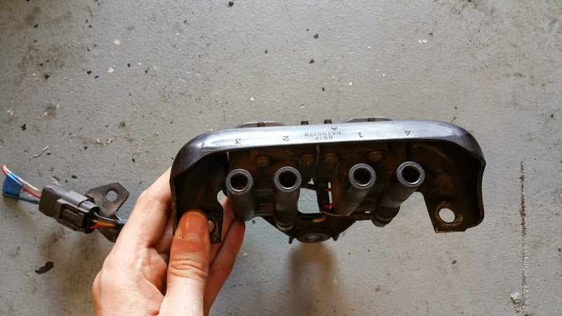
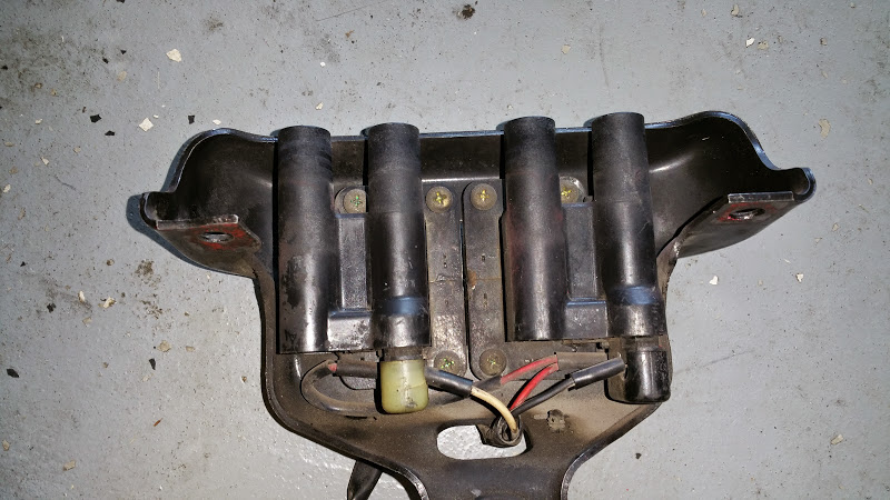
Better view of the bottom of the coils so its clear that at the coils:
White: 2/3 Trigger
Black\White: 1\4 Trigger
Red: +12V
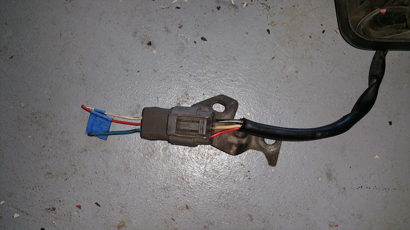
Close up of the connector and mate:
2/3 Trigger: White-> Red
1\4 Trigger: Black\White-> White
+12V: Red->Blue
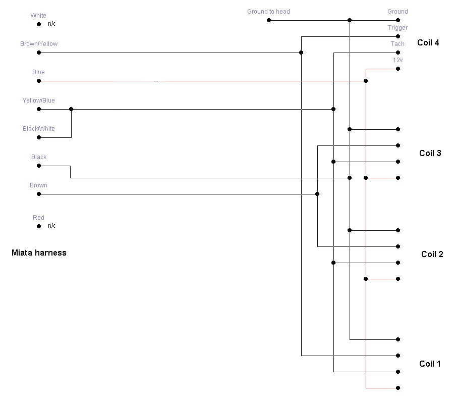
Assuming the ignitor is wired as expected, that would make the brown\yellow wire, Pin 1G on the ECU (Terminal B on the ignitor) the trigger for 1/4 and the brown wire, Pin 1 H on the ECU (Terminal G on the ignitor) the trigger for 2/3
Which is also the opposite that is documented in the OP. I also found this on the COP thread, which would agree with the above assessment (and is actually how I am wiring mine up, I removed the white/red wire from the bundle, I am running Brown\Yellow directly to the 1\4 Trigger and the Brown directly to the 2/3 Trigger.
The coils: Note the white wire coming from the bottom of the 2/3 coil pack and the black\white wire coming from the 1/4 pack
Better view of the bottom of the coils so its clear that at the coils:
White: 2/3 Trigger
Black\White: 1\4 Trigger
Red: +12V
Close up of the connector and mate:
2/3 Trigger: White-> Red
1\4 Trigger: Black\White-> White
+12V: Red->Blue
Assuming the ignitor is wired as expected, that would make the brown\yellow wire, Pin 1G on the ECU (Terminal B on the ignitor) the trigger for 1/4 and the brown wire, Pin 1 H on the ECU (Terminal G on the ignitor) the trigger for 2/3
Which is also the opposite that is documented in the OP. I also found this on the COP thread, which would agree with the above assessment (and is actually how I am wiring mine up, I removed the white/red wire from the bundle, I am running Brown\Yellow directly to the 1\4 Trigger and the Brown directly to the 2/3 Trigger.
Reply
0
0
04-30-2015, 06:47 PM
#157
Junior Member
Join Date: Jul 2009
Location: Orange County, CA
Posts: 419
Total Cats: 45
You guys have me all stirred up about the spark wiring.
The coils: Note the white wire coming from the bottom of the 2/3 coil pack and the black\white wire coming from the 1/4 pack
Better view of the bottom of the coils so its clear that at the coils:
White: 2/3 Trigger
Black\White: 1\4 Trigger
Red: +12V
Close up of the connector and mate:
2/3 Trigger: White-> Red
1\4 Trigger: Black\White-> White
+12V: Red->Blue
Assuming the ignitor is wired as expected, that would make the brown\yellow wire, Pin 1G on the ECU (Terminal B on the ignitor) the trigger for 1/4 and the brown wire, Pin 1 H on the ECU (Terminal G on the ignitor) the trigger for 2/3
Which is also the opposite that is documented in the OP. I also found this on the COP thread, which would agree with the above assessment (and is actually how I am wiring mine up, I removed the white/red wire from the bundle, I am running Brown\Yellow directly to the 1\4 Trigger and the Brown directly to the 2/3 Trigger.
Rev said to route that wire over to the db37 pin 10 as well. I have to wonder though, if it's already on the ecu, why not can't it use the pin that's already there?
Reply
0
0
04-30-2015, 10:09 PM
#159
Former Vendor
Thread Starter
iTrader: (31)
Join Date: Nov 2006
Location: Sunnyvale, CA
Posts: 15,442
Total Cats: 2,099
Ok, I had Trey un-**** the 90-93 wire colors. I'll hand-verify the 01-05 wire colors later this week. Can someone verify that the 94-97 trigger colors are correct?
Reply
0
0
05-01-2015, 12:02 PM
#160
Junior Member
Join Date: Jul 2009
Location: Orange County, CA
Posts: 419
Total Cats: 45
Trigger cyl 2/3: brown
Verified on my 95
Reply
0
0


