
Turbo Exhaust Theory
 03-12-2013, 10:37 AM
#1
Elite Member
Thread Starter
iTrader: (4)

Join Date: Mar 2008
Location: Granbury, TX
Posts: 6,301
Total Cats: 696
Ran across some information posted by a Garrett engineer (Jay Kavanaugh) that I thought would be of general interest. Without further ado . . . :
Howdy,
This thread was brought to my attention by a friend of mine in hopes of shedding some light on the issue of exhaust size selection for turbocharged vehicles. Most of the facts have been covered already. FWIW I'm an turbocharger development engineer for Garrett Engine Boosting Systems.
N/A cars: As most of you know, the design of turbo exhaust systems runs counter to exhaust design for n/a vehicles. N/A cars utilize exhaust velocity (not backpressure) in the collector to aid in scavenging other cylinders during the blowdown process. It just so happens that to get the appropriate velocity, you have to squeeze down the diameter of the discharge of the collector (aka the exhaust), which also induces backpressure. The backpressure is an undesirable byproduct of the desire to have a certain degree of exhaust velocity. Go too big, and you lose velocity and its associated beneficial scavenging effect. Too small and the backpressure skyrockets, more than offsetting any gain made by scavenging. There is a happy medium here.
For turbo cars, you throw all that out the window. You want the exhaust velocity to be high upstream of the turbine (i.e. in the header). You'll notice that primaries of turbo headers are smaller diameter than those of an n/a car of two-thirds the horsepower. The idea is to get the exhaust velocity up quickly, to get the turbo spooling as early as possible. Here, getting the boost up early is a much more effective way to torque than playing with tuned primary lengths and scavenging. The scavenging effects are small compared to what you'd get if you just got boost sooner instead. You have a turbo; you want boost. Just don't go so small on the header's primary diameter that you choke off the high end.
Downstream of the turbine (aka the turboback exhaust), you want the least backpressure possible. No ifs, ands, or buts. Stick a Hoover on the tailpipe if you can. The general rule of "larger is better" (to the point of diminishing returns) of turboback exhausts is valid. Here, the idea is to minimize the pressure downstream of the turbine in order to make the most effective use of the pressure that is being generated upstream of the turbine. Remember, a turbine operates via a pressure ratio. For a given turbine inlet pressure, you will get the highest pressure ratio across the turbine when you have the lowest possible discharge pressure. This means the turbine is able to do the most amount of work possible (i.e. drive the compressor and make boost) with the available inlet pressure.
Again, less pressure downstream of the turbine is goodness. This approach minimizes the time-to-boost (maximizes boost response) and will improve engine VE throughout the rev range.
As for 2.5" vs. 3.0", the "best" turboback exhaust depends on the amount of flow, or horsepower. At 250 hp, 2.5" is fine. Going to 3" at this power level won't get you much, if anything, other than a louder exhaust note. 300 hp and you're definitely suboptimal with 2.5". For 400-450 hp, even 3" is on the small side.
As for the geometry of the exhaust at the turbine discharge, the most optimal configuration would be a gradual increase in diameter from the turbine's exducer to the desired exhaust diameter-- via a straight conical diffuser of 7-12� included angle (to minimize flow separation and skin friction losses) mounted right at the turbine discharge. Many turbochargers found in diesels have this diffuser section cast right into the turbine housing. A hyperbolic increase in diameter (like a trumpet snorkus) is theoretically ideal but I've never seen one in use (and doubt it would be measurably superior to a straight diffuser). The wastegate flow would be via a completely divorced (separated from the main turbine discharge flow) dumptube. Due the realities of packaging, cost, and emissions compliance this config is rarely possible on street cars. You will, however, see this type of layout on dedicated race vehicles.
A large "bellmouth" config which combines the turbine discharge and wastegate flow (without a divider between the two) is certainly better than the compromised stock routing, but not as effective as the above.
If an integrated exhaust (non-divorced wastegate flow) is required, keep the wastegate flow separate from the main turbine discharge flow for ~12-18" before reintroducing it. This will minimize the impact on turbine efficiency-- the introduction of the wastegate flow disrupts the flow field of the main turbine discharge flow.
Necking the exhaust down to a suboptimal diameter is never a good idea, but if it is necessary, doing it further downstream is better than doing it close to the turbine discharge since it will minimize the exhaust's contribution to backpressure. Better yet: don't neck down the exhaust at all.
Also, the temperature of the exhaust coming out of a cat is higher than the inlet temperature, due to the exothermic oxidation of unburned hydrocarbons in the cat. So the total heat loss (and density increase) of the gases as it travels down the exhaust is not as prominent as it seems.
Another thing to keep in mind is that cylinder scavenging takes place where the flows from separate cylinders merge (i.e. in the collector). There is no such thing as cylinder scavenging downstream of the turbine, and hence, no reason to desire high exhaust velocity here. You will only introduce unwanted backpressure.
Other things you can do (in addition to choosing an appropriate diameter) to minimize exhaust backpressure in a turboback exhaust are: avoid crush-bent tubes (use mandrel bends); avoid tight-radius turns (keep it as straight as possible); avoid step changes in diameter; avoid "cheated" radii (cuts that are non-perpendicular); use a high flow cat; use a straight-thru perforated core muffler... etc.
Comparing the two bellmouth designs, I've never seen either one so I can only speculate. But based on your description, and assuming neither of them have a divider wall/tongue between the turbine discharge and wg dump, I'd venture that you'd be hard pressed to measure a difference between the two. The more gradual taper intuitively appears more desirable, but it's likely that it's beyond the point of diminishing returns. Either one sounds like it will improve the wastegate's discharge coefficient over the stock config, which will constitute the single biggest difference. This will allow more control over boost creep. Neither is as optimal as the divorced wastegate flow arrangement, however.
There's more to it, though-- if a larger bellmouth is excessively large right at the turbine discharge (a large step diameter increase), there will be an unrecoverable dump loss that will contribute to backpressure. This is why a gradual increase in diameter, like the conical diffuser mentioned earlier, is desirable at the turbine discharge.
As for primary lengths on turbo headers, it is advantageous to use equal-length primaries to time the arrival of the pulses at the turbine equally and to keep cylinder reversion balanced across all cylinders. This will improve boost response and the engine's VE. Equal-length is often difficult to achieve due to tight packaging, fabrication difficulty, and the desire to have runners of the shortest possible length.
Here's a worked example (simplified) of how larger exhausts help turbo cars:
Say you have a turbo operating at a turbine pressure ratio (aka expansion ratio) of 1.8:1. You have a small turboback exhaust that contributes, say, 10 psig backpressure at the turbine discharge at redline. The total backpressure seen by the engine (upstream of the turbine) in this case is:
(14.5 + 10) x 1.8 = 44.1 psia = 29.6 psig total backpressure
Here, the turbine contributed 19.6 psig of backpressure to the total.
Now you slap on a proper low-backpressure, big turboback exhaust. Same turbo, same boost, etc. You measure 3 psig backpressure at the turbine discharge.
(14.5 + 3) x 1.8 = 31.5 psia = 17 psig total backpressure
In this case the engine sees just 17 psig total backpressure! And the turbine's contribution to the total backpressure is reduced to 14 psig (note: this is 5.6 psig lower than its contribution in the "small turboback" case).
So in the end, the engine saw a reduction in backpressure of 12.6 psig with a turboback that reduced turbine exhaust backpressure by 7psig. This reduction in backpressure is where all the engine's VE gains come from.
This is why larger exhausts make such big gains on nearly all stock turbo cars-- the turbine compounds the downstream backpressure via its expansion ratio. This is also why bigger turbos make more power at a given boost level-- they improve engine VE by operating at lower turbine expansion ratios for a given boost level.
As you can see, the backpressure penalty of running a too-small exhaust (like 2.5" for 350 hp) will vary depending on the match. At a given power level, a smaller turbo will generally be operating at a higher turbine pressure ratio and so will actually make the engine more sensitive to the backpressure downstream of the turbine than a larger turbine/turbo would.
Originally Posted by Jay Kavanaugh
Howdy,
This thread was brought to my attention by a friend of mine in hopes of shedding some light on the issue of exhaust size selection for turbocharged vehicles. Most of the facts have been covered already. FWIW I'm an turbocharger development engineer for Garrett Engine Boosting Systems.
N/A cars: As most of you know, the design of turbo exhaust systems runs counter to exhaust design for n/a vehicles. N/A cars utilize exhaust velocity (not backpressure) in the collector to aid in scavenging other cylinders during the blowdown process. It just so happens that to get the appropriate velocity, you have to squeeze down the diameter of the discharge of the collector (aka the exhaust), which also induces backpressure. The backpressure is an undesirable byproduct of the desire to have a certain degree of exhaust velocity. Go too big, and you lose velocity and its associated beneficial scavenging effect. Too small and the backpressure skyrockets, more than offsetting any gain made by scavenging. There is a happy medium here.
For turbo cars, you throw all that out the window. You want the exhaust velocity to be high upstream of the turbine (i.e. in the header). You'll notice that primaries of turbo headers are smaller diameter than those of an n/a car of two-thirds the horsepower. The idea is to get the exhaust velocity up quickly, to get the turbo spooling as early as possible. Here, getting the boost up early is a much more effective way to torque than playing with tuned primary lengths and scavenging. The scavenging effects are small compared to what you'd get if you just got boost sooner instead. You have a turbo; you want boost. Just don't go so small on the header's primary diameter that you choke off the high end.
Downstream of the turbine (aka the turboback exhaust), you want the least backpressure possible. No ifs, ands, or buts. Stick a Hoover on the tailpipe if you can. The general rule of "larger is better" (to the point of diminishing returns) of turboback exhausts is valid. Here, the idea is to minimize the pressure downstream of the turbine in order to make the most effective use of the pressure that is being generated upstream of the turbine. Remember, a turbine operates via a pressure ratio. For a given turbine inlet pressure, you will get the highest pressure ratio across the turbine when you have the lowest possible discharge pressure. This means the turbine is able to do the most amount of work possible (i.e. drive the compressor and make boost) with the available inlet pressure.
Again, less pressure downstream of the turbine is goodness. This approach minimizes the time-to-boost (maximizes boost response) and will improve engine VE throughout the rev range.
As for 2.5" vs. 3.0", the "best" turboback exhaust depends on the amount of flow, or horsepower. At 250 hp, 2.5" is fine. Going to 3" at this power level won't get you much, if anything, other than a louder exhaust note. 300 hp and you're definitely suboptimal with 2.5". For 400-450 hp, even 3" is on the small side.
As for the geometry of the exhaust at the turbine discharge, the most optimal configuration would be a gradual increase in diameter from the turbine's exducer to the desired exhaust diameter-- via a straight conical diffuser of 7-12� included angle (to minimize flow separation and skin friction losses) mounted right at the turbine discharge. Many turbochargers found in diesels have this diffuser section cast right into the turbine housing. A hyperbolic increase in diameter (like a trumpet snorkus) is theoretically ideal but I've never seen one in use (and doubt it would be measurably superior to a straight diffuser). The wastegate flow would be via a completely divorced (separated from the main turbine discharge flow) dumptube. Due the realities of packaging, cost, and emissions compliance this config is rarely possible on street cars. You will, however, see this type of layout on dedicated race vehicles.
A large "bellmouth" config which combines the turbine discharge and wastegate flow (without a divider between the two) is certainly better than the compromised stock routing, but not as effective as the above.
If an integrated exhaust (non-divorced wastegate flow) is required, keep the wastegate flow separate from the main turbine discharge flow for ~12-18" before reintroducing it. This will minimize the impact on turbine efficiency-- the introduction of the wastegate flow disrupts the flow field of the main turbine discharge flow.
Necking the exhaust down to a suboptimal diameter is never a good idea, but if it is necessary, doing it further downstream is better than doing it close to the turbine discharge since it will minimize the exhaust's contribution to backpressure. Better yet: don't neck down the exhaust at all.
Also, the temperature of the exhaust coming out of a cat is higher than the inlet temperature, due to the exothermic oxidation of unburned hydrocarbons in the cat. So the total heat loss (and density increase) of the gases as it travels down the exhaust is not as prominent as it seems.
Another thing to keep in mind is that cylinder scavenging takes place where the flows from separate cylinders merge (i.e. in the collector). There is no such thing as cylinder scavenging downstream of the turbine, and hence, no reason to desire high exhaust velocity here. You will only introduce unwanted backpressure.
Other things you can do (in addition to choosing an appropriate diameter) to minimize exhaust backpressure in a turboback exhaust are: avoid crush-bent tubes (use mandrel bends); avoid tight-radius turns (keep it as straight as possible); avoid step changes in diameter; avoid "cheated" radii (cuts that are non-perpendicular); use a high flow cat; use a straight-thru perforated core muffler... etc.
Comparing the two bellmouth designs, I've never seen either one so I can only speculate. But based on your description, and assuming neither of them have a divider wall/tongue between the turbine discharge and wg dump, I'd venture that you'd be hard pressed to measure a difference between the two. The more gradual taper intuitively appears more desirable, but it's likely that it's beyond the point of diminishing returns. Either one sounds like it will improve the wastegate's discharge coefficient over the stock config, which will constitute the single biggest difference. This will allow more control over boost creep. Neither is as optimal as the divorced wastegate flow arrangement, however.
There's more to it, though-- if a larger bellmouth is excessively large right at the turbine discharge (a large step diameter increase), there will be an unrecoverable dump loss that will contribute to backpressure. This is why a gradual increase in diameter, like the conical diffuser mentioned earlier, is desirable at the turbine discharge.
As for primary lengths on turbo headers, it is advantageous to use equal-length primaries to time the arrival of the pulses at the turbine equally and to keep cylinder reversion balanced across all cylinders. This will improve boost response and the engine's VE. Equal-length is often difficult to achieve due to tight packaging, fabrication difficulty, and the desire to have runners of the shortest possible length.
Here's a worked example (simplified) of how larger exhausts help turbo cars:
Say you have a turbo operating at a turbine pressure ratio (aka expansion ratio) of 1.8:1. You have a small turboback exhaust that contributes, say, 10 psig backpressure at the turbine discharge at redline. The total backpressure seen by the engine (upstream of the turbine) in this case is:
(14.5 + 10) x 1.8 = 44.1 psia = 29.6 psig total backpressure
Here, the turbine contributed 19.6 psig of backpressure to the total.
Now you slap on a proper low-backpressure, big turboback exhaust. Same turbo, same boost, etc. You measure 3 psig backpressure at the turbine discharge.
(14.5 + 3) x 1.8 = 31.5 psia = 17 psig total backpressure
In this case the engine sees just 17 psig total backpressure! And the turbine's contribution to the total backpressure is reduced to 14 psig (note: this is 5.6 psig lower than its contribution in the "small turboback" case).
So in the end, the engine saw a reduction in backpressure of 12.6 psig with a turboback that reduced turbine exhaust backpressure by 7psig. This reduction in backpressure is where all the engine's VE gains come from.
This is why larger exhausts make such big gains on nearly all stock turbo cars-- the turbine compounds the downstream backpressure via its expansion ratio. This is also why bigger turbos make more power at a given boost level-- they improve engine VE by operating at lower turbine expansion ratios for a given boost level.
As you can see, the backpressure penalty of running a too-small exhaust (like 2.5" for 350 hp) will vary depending on the match. At a given power level, a smaller turbo will generally be operating at a higher turbine pressure ratio and so will actually make the engine more sensitive to the backpressure downstream of the turbine than a larger turbine/turbo would.

Reply
 1
1

1

 03-12-2013, 11:02 AM
#3

Originally Posted by Jay Kavanaugh
As for 2.5" vs. 3.0", the "best" turboback exhaust depends on the amount of flow, or horsepower. At 250 hp, 2.5" is fine. Going to 3" at this power level won't get you much, if anything, other than a louder exhaust note.
Reply
0
0
03-12-2013, 11:08 AM
#4
I think he kinda answers it in his prior statement:
Downstream of the turbine (aka the turboback exhaust), you want the least backpressure possible. No ifs, ands, or buts. Stick a Hoover on the tailpipe if you can. The general rule of "larger is better" (to the point of diminishing returns) of turboback exhausts is valid. Here, the idea is to minimize the pressure downstream of the turbine in order to make the most effective use of the pressure that is being generated upstream of the turbine. Remember, a turbine operates via a pressure ratio. For a given turbine inlet pressure, you will get the highest pressure ratio across the turbine when you have the lowest possible discharge pressure. This means the turbine is able to do the most amount of work possible (i.e. drive the compressor and make boost) with the available inlet pressure.
Again, less pressure downstream of the turbine is goodness. This approach minimizes the time-to-boost (maximizes boost response) and will improve engine VE throughout the rev range.
Again, less pressure downstream of the turbine is goodness. This approach minimizes the time-to-boost (maximizes boost response) and will improve engine VE throughout the rev range.
Reply
0
0
03-12-2013, 11:14 AM
#5
I guess. But it seems to me he could have made the same point by saying at <250hp going from 3" to 3.5" won't see anything other than more noise. Although I guess I can't say that for sure until someone dynos a 3" and then pulls it off and does the same with a 3.5" without significant gains. Which probably aint gonna happen around 250hp.
Reply
0
0

 03-12-2013, 11:44 AM
#8
Boost Czar


iTrader: (62)
Join Date: May 2005
Location: Chantilly, VA
Posts: 79,488
Total Cats: 4,078
I guess. But it seems to me he could have made the same point by saying at <250hp going from 3" to 3.5" won't see anything other than more noise. Although I guess I can't say that for sure until someone dynos a 3" and then pulls it off and does the same with a 3.5" without significant gains. Which probably aint gonna happen around 250hp.
I'd much prefer to have a 3.5" cat and catback.
Remember, as exhaust gasses travel through the exhaust, they cool, slow, and start piling up in the pipes.
So you want gasses to stay hot and fast out of the turbine (2" DP) but also give gasses room to breathe and GTFO (3" Exhaust).

Reply
0
0
 03-12-2013, 01:05 PM
#10
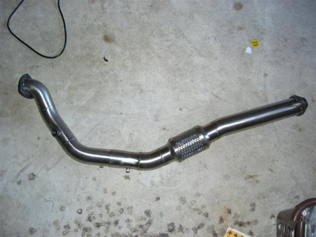
I have the same outlet, and almost the same exact dp, but it never transitions to 3", just stays at 2.5 
I have all the stuff to make it taper to 3" perfectly, but keep wondering if its really necessary to replace the roughly 2' of 2.5 to 3. Or just keep it as is. Rest of the exhaust is 3
I have all the stuff to make it taper to 3" perfectly, but keep wondering if its really necessary to replace the roughly 2' of 2.5 to 3. Or just keep it as is. Rest of the exhaust is 3
Reply
0
0

 03-12-2013, 01:40 PM
#14
Boost Czar
iTrader: (62)
Join Date: May 2005
Location: Chantilly, VA
Posts: 79,488
Total Cats: 4,078
I'd prefer it, but I dunno. Obviously a smooth transition would the more ideal way to go.
Would you design an IM manifold to have smooth tapered runners or big steps?
Would you design an IM manifold to have smooth tapered runners or big steps?
Reply
0
0
 03-12-2013, 01:46 PM
#17
You don't need to taper over 2' though, you can do it much faster than that. You could taper it from 2.5" to 3" with a 2.35" cone. If you are running a 2.5" DP for space reasons that is one thing. I am just wondering what (if any) performance gains you would see from going bigger earlier. If you can gain significant HP by going from 2.5" to 3" after the cat, would there be similar gains if you went to 3" asap?
Of course smoother is better, and bigger is better. But how much better?
Of course smoother is better, and bigger is better. But how much better?
Reply
0
0
03-12-2013, 02:05 PM
#19
Senior Member

Join Date: Apr 2011
Location: Martin, Slovakia
Posts: 507
Total Cats: 74
You'll notice that primaries of turbo headers are smaller diameter than those of an n/a car of two-thirds the horsepower. The idea is to get the exhaust velocity up quickly, to get the turbo spooling as early as possible.
5/4 (43mm od) is the stock runner size. Most of the fabbed manifolds use 6/4 ( 48mm od) which seems at odds with the notion of using a smaller diameter than the n/a application? Begi s4 uses thin wall tubing with an outside diameter of approx 39mm. Any thoughts?
Reply
0
0
03-12-2013, 02:14 PM
#20
Ideal for what case? How much power do you want to make? For almost everyone on this site IMO even sch40 1.25" might be bigger than needed. That should flow sufficiently for 400-450hp with the right EGTs. But once you get to that upper end, going to thin wall 1.25 or thick wall 1.5 would likely yield gains.
Reply
0
0


