
How to wire VVT engine on an NA
 04-15-2012, 10:17 PM
#1
Senior Member
Thread Starter
iTrader: (3)

Join Date: Oct 2008
Location: Indianapolis
Posts: 610
Total Cats: 12
Hey guys, I just bought a 2001 engine and 6 speed transmission from ATANK. I know I will need some help wiring this engine harness to run on my NA.
The reason I am posting this is because I am a very visual person and have trouble comprehending how to wire things. I have read numerous posts but I will like to put everything on one and call it done.
My intention is to take a lot of pictures during the process of wiring the VVT engine so other people like me can understand how to do it and have an informative thread to look at.
I will be running a Reverend made Megasquirt with VVT tuning capabilities.
-As you can see on these first pictures, ATANK did not cut the engine harness when he removed the engine, except for the main wires that go through the firewall to inside the car. Those wires are cut, but they were cut inside the car passenger compartment. You can also see that the VVT fuse box is there and even the wires that go to the battery are intact.
Also the 6 speed tranny wires are all still hooked, I would like to use the 6 speed transmission connectors and not have to swap to the 5 speed NA connectors
My question is, can i cut the wires inside my NA and splice most of the wires that came with the VVT to the NA harness?
What is the easiest, most clean way to go about doing all the wiring?
picture 1
picture 2
picture 3
picture 4
picture 5
picture 6
picture 7
Last edited by y8s; 04-16-2012 at 10:01 AM. Reason: lars is a n00b.

Reply
 0
0

0


 04-15-2012, 10:52 PM
#3
Former Vendor

iTrader: (31)

Join Date: Nov 2006
Location: Sunnyvale, CA
Posts: 15,442
Total Cats: 2,099
I get the idea that your plan is to somehow splice the cut '01 harness into your factory harness at one point, using the VVT fusebox and 6-speed wiring. This is a terrible, terrible idea, and it will create a TON of unnecessary work. Don't do it that way, no matter how much you think it's a good idea, and no matter how much others have told you to do it that way.
The easiest way to swap a VVT motor into an early chassis is to use as much of the original engine wiring as possible, and then add the incorrect bits last. I've done 3 or 4 of them now, and this is the method that involves the least amount of wiring alterations.
The stuff that will remain the same:
The stuff you'll add:
I may have forgotten something here or there, so if you encounter something odd just shout out. In general the philosophy here is to keep your OEM wiring and sensors whenever possible, and just take bits and pieces from the 01+ harness as needed.
The easiest way to swap a VVT motor into an early chassis is to use as much of the original engine wiring as possible, and then add the incorrect bits last. I've done 3 or 4 of them now, and this is the method that involves the least amount of wiring alterations.
The stuff that will remain the same:
- All of the starter and alternator wiring, as well as the OPG wiring (use a 94-97 1.8 alternator and the OPG sender that corresponds with your gauges)
- The injector and coolant temp sensor wiring. You should pull the +12v for the VVT solenoid from this harness - it's the easiest, closest +12v. Your old CLT sensors (for the ECU and gauges) will carry over to the new engine.
- The wiring for the TPS and IAC (the connectors are different, but the wiring itself is the same) (Note for 1.6 guys, you'll either not use the variable TPS or you'll need to move some stuff at your ECU connector to use the factory TPS wiring)
The stuff you'll add:
- The cam/crank wiring. The OEM CAS has a 4-wire connector - you have a +12v, a ground, a cam sensor wire, and a crank sensor wire. Feed +12v and Ground to both of the NB sensors, hook up the cam signal to the cam sensor, and the crank signal to the crank sensor. Easy-peasy.
- The VVT signal wire. Grab +12v from the injector harness and then run your own wire for the signal to the control solenoid. There is no polarity, so hook up the +12v to either pin.
- TPS and IAC pigtails. The IAC is easy, since there's no polarity, but you'll need to pay attention to which wire goes where on the TPS connector. Each car has slightly different wire colors so there's no color-by-numbers for this one. I will usually hook it up temporarily, confirm the TPS function, and then make the connections permanent.
- Coil wiring. If you have a 94-97 NA, this is pretty easy - just hook up the wires as you otherwise would, and then use your ECU to drive the tachometer. If you have a 90-93 NA, it's slightly more complicated, as you'll need to bypass the OEM ignitor before you hook up to the OEM wires. This assumes you're using the 2001+ coils - if you're doing LS coils or keeping your factory NA coils, then you don't have to touch the wiring here.
I may have forgotten something here or there, so if you encounter something odd just shout out. In general the philosophy here is to keep your OEM wiring and sensors whenever possible, and just take bits and pieces from the 01+ harness as needed.
Reply
4
4
04-15-2012, 11:06 PM
#4
mkturbo.com

iTrader: (24)
Join Date: May 2006
Location: Charleston SC
Posts: 15,176
Total Cats: 1,680
I get the idea that your plan is to somehow splice the cut '01 harness into your factory harness at one point, using the VVT fusebox and 6-speed wiring. This is a terrible, terrible idea, and it will create a TON of unnecessary work. Don't do it that way, no matter how much you think it's a good idea, and no matter how much others have told you to do it that way.
The easiest way to swap a VVT motor into an early chassis is to use as much of the original engine wiring as possible, and then add the incorrect bits last. I've done 3 or 4 of them now, and this is the method that involves the least amount of wiring alterations.
The stuff that will remain the same:
The stuff you'll add:
I may have forgotten something here or there, so if you encounter something odd just shout out. In general the philosophy here is to keep your OEM wiring and sensors whenever possible, and just take bits and pieces from the 01+ harness as needed.
The easiest way to swap a VVT motor into an early chassis is to use as much of the original engine wiring as possible, and then add the incorrect bits last. I've done 3 or 4 of them now, and this is the method that involves the least amount of wiring alterations.
The stuff that will remain the same:
- All of the starter and alternator wiring, as well as the OPG wiring (use a 94-97 1.8 alternator and the OPG sender that corresponds with your gauges)
- The injector and coolant temp sensor wiring. You should pull the +12v for the VVT solenoid from this harness - it's the easiest, closest +12v. Your old CLT sensors (for the ECU and gauges) will carry over to the new engine.
- The wiring for the TPS and IAC (the connectors are different, but the wiring itself is the same) (Note for 1.6 guys, you'll either not use the variable TPS or you'll need to move some stuff at your ECU connector to use the factory TPS wiring)
The stuff you'll add:
- The cam/crank wiring. The OEM CAS has a 4-wire connector - you have a +12v, a ground, a cam sensor wire, and a crank sensor wire. Feed +12v and Ground to both of the NB sensors, hook up the cam signal to the cam sensor, and the crank signal to the crank sensor. Easy-peasy.
- The VVT signal wire. Grab +12v from the injector harness and then run your own wire for the signal to the control solenoid. There is no polarity, so hook up the +12v to either pin.
- TPS and IAC pigtails. The IAC is easy, since there's no polarity, but you'll need to pay attention to which wire goes where on the TPS connector. Each car has slightly different wire colors so there's no color-by-numbers for this one. I will usually hook it up temporarily, confirm the TPS function, and then make the connections permanent.
- Coil wiring. If you have a 94-97 NA, this is pretty easy - just hook up the wires as you otherwise would, and then use your ECU to drive the tachometer. If you have a 90-93 NA, it's slightly more complicated, as you'll need to bypass the OEM ignitor before you hook up to the OEM wires. This assumes you're using the 2001+ coils - if you're doing LS coils or keeping your factory NA coils, then you don't have to touch the wiring here.
I may have forgotten something here or there, so if you encounter something odd just shout out. In general the philosophy here is to keep your OEM wiring and sensors whenever possible, and just take bits and pieces from the 01+ harness as needed.
Reply
0
0
04-15-2012, 11:45 PM
#5
Senior Member
Thread Starter
iTrader: (3)
Join Date: Oct 2008
Location: Indianapolis
Posts: 610
Total Cats: 12
Savington, thank you very much for your How To. I think you answered all my questions. I usually try to search for answers instead of posting, but thanks for your patience and excellent explanation
Reply
0
0
 02-15-2013, 09:22 PM
#11

Sorry to totally necro a thread, but I'm in the middle of a VVT swap into my '94 and confused as ****. Thought it would be better to have this all in one thread.
Is the Savington approach outlined above still the best way to go? I know for Emilio's 95 they just cut a new hole in the firewall, but that's a lot more work than I'm willing to do right now. I feel like the guys in the MegaSquirt threads all want me to use 100% VVT donor wiring.
How are you all "altering" the harness? Are you cutting and splicing inside the engine bay? I thought that was completely forbidden?
I'm assuming that you're reusing EGR, purge, and other wires for things like the VVT solenoid.
So, where (and what method) are you modifying your harness?
I really, really, REALLY don't want my engine bay to look like this: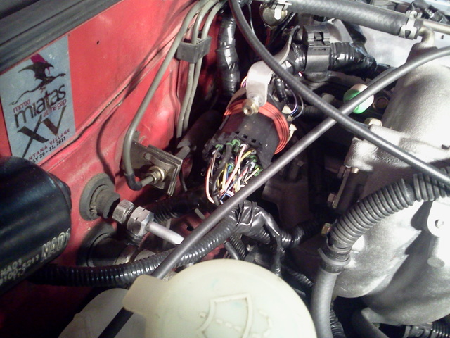
Reply
0
0
02-16-2013, 01:52 AM
#12
Former Vendor
iTrader: (31)
Join Date: Nov 2006
Location: Sunnyvale, CA
Posts: 15,442
Total Cats: 2,099
Anyone who suggests any way other than what I've outlined above has not done their homework. I've done several of these swaps, and my way is the easiest and simplest way.
Reply
0
0
02-16-2013, 07:38 AM
#13
Thanks Andrew,
One more pedantic clarification: you're cutting and splicing in the engine bay? Are you soldering or crimping? Do you make your edits at the connector end, or back close to the firewall?
I don't want to **** this up. I know the details are minor, but I'd feel better knowing I did it exactly right rather than just wrong enough.
Thanks!
Last edited by thebeerbaron; 02-16-2013 at 01:54 PM.
Reply
0
0
02-16-2013, 09:18 AM
#14
Senior Member

Join Date: Apr 2011
Location: Hollywood, FL
Posts: 807
Total Cats: 163
Is this a more acceptable look for you?
Im running SCCA autox and I dont really know what the intent of the wording of the wiring harness is in the rule book. SOme folks cut and splice the harness to add/rewire the VVT engine in but since the rulebook says no modifying of the harness as it is a separate component I tried not touching mine. Here's what I did do though. I put the cam sensor signal through the CAS wires by cutting off the CAS connector, not the wiring harness connector mind you. I then cut back enough of the plastic to expose the pins and soldered wires onto that to a pigtail that came with the donor VVT engine. Did the same with the connectors on the coils to wire in the VVT coils, took two evap vacuum solenoids and did the same for the VVT solenoid. I ran the crank sensor through the MAF sensor connector but didnt cut the MAF connector off since the pins are large enough that I could stick spade connectors into the MAF connector harness side. The MAF connector also has the IAT running through it. Not a single wire was cut on the harness and all soldering was done in my house. Since I run a DIYPNP, I just jumpered the proper wires inside to the new locations and done. The only bonehead thing I did was hot glue the soldered cutback old connectors for fear of the wires arching. My dumbass self should of known the underhood temps would melt the glue. Since they are all taped up the glue hasnt run out yet but when up to proper temp the connectors are jelly soft. Maybe a high temp glue might work as that requires upwards of 300* to melt.
Im running SCCA autox and I dont really know what the intent of the wording of the wiring harness is in the rule book. SOme folks cut and splice the harness to add/rewire the VVT engine in but since the rulebook says no modifying of the harness as it is a separate component I tried not touching mine. Here's what I did do though. I put the cam sensor signal through the CAS wires by cutting off the CAS connector, not the wiring harness connector mind you. I then cut back enough of the plastic to expose the pins and soldered wires onto that to a pigtail that came with the donor VVT engine. Did the same with the connectors on the coils to wire in the VVT coils, took two evap vacuum solenoids and did the same for the VVT solenoid. I ran the crank sensor through the MAF sensor connector but didnt cut the MAF connector off since the pins are large enough that I could stick spade connectors into the MAF connector harness side. The MAF connector also has the IAT running through it. Not a single wire was cut on the harness and all soldering was done in my house. Since I run a DIYPNP, I just jumpered the proper wires inside to the new locations and done. The only bonehead thing I did was hot glue the soldered cutback old connectors for fear of the wires arching. My dumbass self should of known the underhood temps would melt the glue.
Since they are all taped up the glue hasnt run out yet but when up to proper temp the connectors are jelly soft. Maybe a high temp glue might work as that requires upwards of 300* to melt.
Reply
0
0
02-16-2013, 01:52 PM
#15

Thanks Sav,
One more pedantic clarification: you're cutting and splicing in the engine bay? Are you soldering or crimping? Do you make your edits at the connector end, or back close to the firewall?
I don't want to **** this up. I know the details are minor, but I'd feel better knowing I did it exactly right rather than just wrong enough.
Thanks!
When soldering, heatshrink the connection then wrap it in electrical tape.
Reply
0
0
02-17-2013, 06:51 PM
#16
Former Vendor
iTrader: (31)
Join Date: Nov 2006
Location: Sunnyvale, CA
Posts: 15,442
Total Cats: 2,099
I prefer crimps over solder. All the edits happen at the connector end in the engine bay - you're just extending the CAS harness and changing a couple of connectors.
Reply
0
0
02-17-2013, 08:27 PM
#18
Tour de Franzia
iTrader: (6)
Join Date: Jun 2006
Location: Republic of Dallas
Posts: 29,085
Total Cats: 375
I've had more crimp connections fail than solder. I buy old engine harnesses to keep the colors consistent with the 2001+ generation cars, strip, flux, and heat-shrink every connection.
Reply
0
0
02-17-2013, 08:30 PM
#19
Former Vendor
iTrader: (31)
Join Date: Nov 2006
Location: Sunnyvale, CA
Posts: 15,442
Total Cats: 2,099
You suck at crimping. Solder introduces a stiff joint in an application where vibration is the norm, which is why even high-end motorsport harnesses are all crimped.
Reply
0
0
02-17-2013, 08:37 PM
#20
Tour de Franzia
iTrader: (6)
Join Date: Jun 2006
Location: Republic of Dallas
Posts: 29,085
Total Cats: 375
For my 1991 I drilled a .5" hole in the trans-tunnel on the passenger side and passed all accessory electronics (gauges) and grounds through there including the two additional injector wires. I ran that bundle up to the old igniter area. From there I used a 2001 fuel-injector harness connector for all fuel injectors (power and 4 trigger wires) leaving 3 spare wires. This was perfect to also run the two CLT wires and a third wire for my custom water temp gauge. The VVT solenoid is run through purge (yel/red) wire and I use power from that same connection (pin x on OEM connector 2). I then used the old 4-wire injector harness connector for the CMP and CKP wires.
On my 1995 I basically did the same thing, but didn't have to jack with the fuel injector wiring because it came with sequential fuel from the factory. I used Weather-pack connectors for all other stuff.
This way i can pull the engine by disconnecting 5 connectors, unbolt the starter wire, unbolt the alternator wire, disconnect the fuel lines, and pull the engine. All the ground wires, fuel injector wiring, and CKP/CMP wiring stays on the engine when you pull it. It's also crazy clean and awesome.
My biggest tip for you is to make a clear, easy to read swap-diagram. Buy good solder and use flux. Don't trust Mazda service manuals or Madracki, use my guides because there were errors elsewhere. Finally, don't get drunk while you do this, lol.
Reply
1
1


