
DIY lightweight crank
 04-07-2016, 04:20 AM
#1
ʎpunq qoq
Thread Starter

Join Date: Jan 2014
Location: Western Australia
Posts: 604
Total Cats: 201
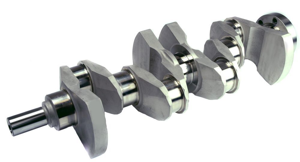
Three words that probably should never go together... especially on a turbo miata forum. Still I had a spare crank and felt like spending many back breaking hours at the mill so why not?
The concept is to take out most of the weight from counterweights no 2, 3, 6, 7 to form a hybrid SOHC and DOHC crank setup. I might also knife edge these counterweights to reduce the MoI and air friction. There are a few cosworth cranks set up like this, and I hear a lot of racers use the SOHC to achieve a similar result. My theory is that the forged DOHC is stronger, so getting something closer to the SOHC in weight but retaining 95% of the strength of the forging.
This crank may one day make it into my >8500 rpm N/A race engine... if it survives a pressure test in a spare engine first.
Here are a few pics of the progress:


I was planning on cutting down all counterweights but Emilio suggested that it probably wasn't a great idea and it would chew main bearings. I'm hoping that this hybrid approach is better... but who really knows until it's done.
That's half the crank done, still have to do the other side, then it's off to the lathe to take more weight off.
Don't expect many updates on this thread, but I'll post back progress.
The concept is to take out most of the weight from counterweights no 2, 3, 6, 7 to form a hybrid SOHC and DOHC crank setup. I might also knife edge these counterweights to reduce the MoI and air friction. There are a few cosworth cranks set up like this, and I hear a lot of racers use the SOHC to achieve a similar result. My theory is that the forged DOHC is stronger, so getting something closer to the SOHC in weight but retaining 95% of the strength of the forging.
This crank may one day make it into my >8500 rpm N/A race engine... if it survives a pressure test in a spare engine first.
Here are a few pics of the progress:
I was planning on cutting down all counterweights but Emilio suggested that it probably wasn't a great idea and it would chew main bearings. I'm hoping that this hybrid approach is better... but who really knows until it's done.
That's half the crank done, still have to do the other side, then it's off to the lathe to take more weight off.
Don't expect many updates on this thread, but I'll post back progress.

Reply
 2
2

2

 04-07-2016, 10:03 PM
#5
ʎpunq qoq
Thread Starter
Join Date: Jan 2014
Location: Western Australia
Posts: 604
Total Cats: 201
I suppose knife edging in a radial sense is more for weight reduction escpecially MoI reduction than reducing drag, although that part of the crank is spinning the fastest so removing a decent sized triangle would reduce drag. The problem is once the crank is knife edged, there is no flat surface to drill the balancing holes, making balancing the crank more expensive.
I was thinking of bull edging the leading edge and tapering the trailing however I'm trying to keep all material removal symmetrical to maintain balance. I was thinking of rotating the mill head to 45deg and taking a chamfer off each side of the counterweight where I have machined it flat. It's all done manually though so I'd just need to be careful to match the material removed on each counterweight.
Does the counterweight need to be balanced on each side of the centerline of the crank? So if one side has a rounded edge, and the other a taper does the material removed need to be equal? I'll probably do some minor blending of surfaces with a flapper disk so there are no sharp edges, but I figure the material I remove with a flapper won't be a lot and should be fairly equal across the crank.
The other thing is I'm running Wiseco Pistons and Crower rods. I think the pistons are around 120 grams lighter than stock and the rods, 20-30 grams. That means I should be able to take a bit off all counterweights anyway.
Reply
0
0
04-07-2016, 10:22 PM
#6

i would stop and talk with someone who balances rotating assemblies and talk about reducing rocking couple. there is an ideal amout you want to be taking off with the reduced weight of your rods and pistons.
also does your balancer person dynamically balance the assembly?
i also dont particularly agree with removing material on the same plane for counterweights 2 and 7 as the center 4.
also does your balancer person dynamically balance the assembly?
i also dont particularly agree with removing material on the same plane for counterweights 2 and 7 as the center 4.
Reply
0
0
04-07-2016, 10:40 PM
#7
ʎpunq qoq
Thread Starter
Join Date: Jan 2014
Location: Western Australia
Posts: 604
Total Cats: 201
Once I've finished the bulk material removal on the mill, I'll take the crank to my machinist and see what he thinks regarding the bull nosing and knife edging. I want to keep costs fairly low as this is just an experiment, so I'll find out what impacts on the balancing he does. I assume he has the best gear for crank balancing as he services all the motorsport guys. I'll find out what he can do.
Where I'm removing weight at this stage is based solely of the SOHC cranks and some of the cosworth billet cranks I've seen. I'll keep everything symmetrical at this stage. Maybe the weight reduction in the middle of the two halves of the crank reduces the load from the rocking couple?
I don't know much that much about it all really, which I figure is the best reason to do it.
Reply
1
1

 04-07-2016, 11:18 PM
#11
Three words that probably should never go together... especially on a turbo miata forum. Still I had a spare crank and felt like spending many back breaking hours at the mill so why not?
The concept is to take out most of the weight from counterweights no 2, 3, 6, 7 to form a hybrid SOHC and DOHC crank setup. I might also knife edge these counterweights to reduce the MoI and air friction. There are a few cosworth cranks set up like this, and I hear a lot of racers use the SOHC to achieve a similar result. My theory is that the forged DOHC is stronger, so getting something closer to the SOHC in weight but retaining 95% of the strength of the forging.
This crank may one day make it into my >8500 rpm N/A race engine... if it survives a pressure test in a spare engine first.
Here are a few pics of the progress:
.....
I was planning on cutting down all counterweights but Emilio suggested that it probably wasn't a great idea and it would chew main bearings. I'm hoping that this hybrid approach is better... but who really knows until it's done.
That's half the crank done, still have to do the other side, then it's off to the lathe to take more weight off.
Don't expect many updates on this thread, but I'll post back progress.
Reply
0
0
04-07-2016, 11:48 PM
#12
ʎpunq qoq
Thread Starter
Join Date: Jan 2014
Location: Western Australia
Posts: 604
Total Cats: 201
I'm definitely trying to not weaken the crank much. So far all my cuts are taking material from areas where there is little to no load transfer. I think the stock cranks are suitably strong enough to sustain a lot of power as you yourself has proved. Hopefully this gives me a good error buffer in terms of crank strength. If I only remove counterweight material then the main concern I have will be in regards to balance and creating harmonics that shouldn't be there.
Given that I've been running a stock crank which is heavier than it should be for the pistons and rods I'm running, I should be able to flip to the inverse and run a lighter crank without stressing it more than before. I think there is a good error factor in all of this stuff, with the only main issue being excessive main bearing wear due to the crank flexing. Still if the crank is lighter there should be less flex? Maybe, maybe not.
Emilio has warned me that the lightweight crank experiment he tried cracked a main bearing cap and spun a bearing whilst reving to 8500. That advise made me change my plans to take less weight off the crank and keep it more inline with the SOHC crank and the billet crank 949 offers. I already do a yearly rebuild, probably with less than 15 hours on the engine so as long as my bearings last that long it's all fine. I don't mind spinning a main bearing as long as it doesn't throw a rod and take out the head.
I mentioned it before, but I plan on dropping this crank into a stock engine and stress testing prior to moving it to my race engine. It's a long term project and I doubt I'll have results for a year or so, and by then I might decide to go for big Rotrex power instead and not even run this crank.
Reply
0
0
04-08-2016, 12:40 AM
#14
I'm definitely trying to not weaken the crank much. So far all my cuts are taking material from areas where there is little to no load transfer. I think the stock cranks are suitably strong enough to sustain a lot of power as you yourself has proved. Hopefully this gives me a good error buffer in terms of crank strength. If I only remove counterweight material then the main concern I have will be in regards to balance and creating harmonics that shouldn't be there.
Given that I've been running a stock crank which is heavier than it should be for the pistons and rods I'm running, I should be able to flip to the inverse and run a lighter crank without stressing it more than before. I think there is a good error factor in all of this stuff, with the only main issue being excessive main bearing wear due to the crank flexing. Still if the crank is lighter there should be less flex? Maybe, maybe not.
Emilio has warned me that the lightweight crank experiment he tried cracked a main bearing cap and spun a bearing whilst reving to 8500. That advise made me change my plans to take less weight off the crank and keep it more inline with the SOHC crank and the billet crank 949 offers. I already do a yearly rebuild, probably with less than 15 hours on the engine so as long as my bearings last that long it's all fine. I don't mind spinning a main bearing as long as it doesn't throw a rod and take out the head.
I mentioned it before, but I plan on dropping this crank into a stock engine and stress testing prior to moving it to my race engine. It's a long term project and I doubt I'll have results for a year or so, and by then I might decide to go for big Rotrex power instead and not even run this crank.
Given that I've been running a stock crank which is heavier than it should be for the pistons and rods I'm running, I should be able to flip to the inverse and run a lighter crank without stressing it more than before. I think there is a good error factor in all of this stuff, with the only main issue being excessive main bearing wear due to the crank flexing. Still if the crank is lighter there should be less flex? Maybe, maybe not.
Emilio has warned me that the lightweight crank experiment he tried cracked a main bearing cap and spun a bearing whilst reving to 8500. That advise made me change my plans to take less weight off the crank and keep it more inline with the SOHC crank and the billet crank 949 offers. I already do a yearly rebuild, probably with less than 15 hours on the engine so as long as my bearings last that long it's all fine. I don't mind spinning a main bearing as long as it doesn't throw a rod and take out the head.
I mentioned it before, but I plan on dropping this crank into a stock engine and stress testing prior to moving it to my race engine. It's a long term project and I doubt I'll have results for a year or so, and by then I might decide to go for big Rotrex power instead and not even run this crank.
A lighter crank does not flex less. A stronger/stiffer crank will flex less. A crankshaft that is well balanced will flex less than a crank that is not-as-well balanced since it will see less loading (from vibration induced from the imbalance). I do understand you're building a different machine than I do, so your looking for any power you can find. I personally would never do what you're doing but my goals are different, I put reliability ahead of everything. If I wanted to improve the bottom end, I'd spring for forged main caps and have the bottom end very well balanced. My current engine was balanced well, but I run stock caps (though I use ARP studs and had the mains line-honed at target torque). If I could do it over, I'd have forged caps. I would recommend them to you with your goals.
Reply
0
0
04-08-2016, 02:08 AM
#15
ʎpunq qoq
Thread Starter
Join Date: Jan 2014
Location: Western Australia
Posts: 604
Total Cats: 201
Re: the main caps, I'll see how I go. I'm fairly cost adverse so I'm not sure if they are in the budget.
I figured a lighter crank has less energy so deflection would be less. But I suppose the load is all based from the rods anyway so crank weight is probably a very very minor factor.
Reliability is one thing, but to get 200whp out of a N/A you have to push everything to the limit. Already I have removed lots of points of failure from the engine by keeping everything as simple and minimal as possible. I think I can get 15-20whp more out of it with a few small but additive mods. Smoothing out the intake runners, building a tuned CAI, removing the water pump and running EWP, increasing the revs to 9000 (HP is still creeping upwards at 8500)...
Reply
0
0
04-08-2016, 03:58 AM
#16
Re: the main caps, I'll see how I go. I'm fairly cost adverse so I'm not sure if they are in the budget.
I figured a lighter crank has less energy so deflection would be less. But I suppose the load is all based from the rods anyway so crank weight is probably a very very minor factor.
Reliability is one thing, but to get 200whp out of a N/A you have to push everything to the limit. Already I have removed lots of points of failure from the engine by keeping everything as simple and minimal as possible. I think I can get 15-20whp more out of it with a few small but additive mods. Smoothing out the intake runners, building a tuned CAI, removing the water pump and running EWP, increasing the revs to 9000 (HP is still creeping upwards at 8500)...
I figured a lighter crank has less energy so deflection would be less. But I suppose the load is all based from the rods anyway so crank weight is probably a very very minor factor.
Reliability is one thing, but to get 200whp out of a N/A you have to push everything to the limit. Already I have removed lots of points of failure from the engine by keeping everything as simple and minimal as possible. I think I can get 15-20whp more out of it with a few small but additive mods. Smoothing out the intake runners, building a tuned CAI, removing the water pump and running EWP, increasing the revs to 9000 (HP is still creeping upwards at 8500)...
Reply
0
0
04-11-2016, 06:56 PM
#17
Being cost adverse and having a mill, just order some 4140 PHT and crank your own out undersized and torque them to the block for the machine shop to line bore it. Do your own engineering here, 4140 PHT sounds good off the top of my head but you might want something more extreme.
Reply
0
0
04-11-2016, 06:59 PM
#18
SADFab Destructive Testing Engineer


iTrader: (5)
Join Date: Apr 2014
Location: Beaverton, USA
Posts: 18,642
Total Cats: 1,866
Being cost adverse and having a mill, just order some 4140 PHT and crank your own out undersized and torque them to the block for the machine shop to line bore it. Do your own engineering here, 4140 PHT sounds good off the top of my head but you might want something more extreme.
Reply
0
0
04-11-2016, 07:54 PM
#19
ʎpunq qoq
Thread Starter
Join Date: Jan 2014
Location: Western Australia
Posts: 604
Total Cats: 201
Being cost adverse and having a mill, just order some 4140 PHT and crank your own out undersized and torque them to the block for the machine shop to line bore it. Do your own engineering here, 4140 PHT sounds good off the top of my head but you might want something more extreme.
The existing caps are just cast steel so even billet steel would be better. The ones for sale are advertised as 'billet steel' so stepping up to 4140 would be even better.
Problem would be lathing out the center bore and accurately drilling the mounting holes. If I mount them in pairs in the lathe then I could get the center bore fairly close which it would need so that the line bore doesn't offset the crank. Center bore will need to be within 0.1mm of the bore in the block. I'm not sure my machining skills are up to the task.
I'd also need to add the bearing tag hole.
Hmmmm I have a few projects already. I just bought a second hand EWP and a lightweight suzuki alternator. I'm going to ditch the stock water pump housing and make a billet plate to hold the idlers and move the alternator to the hot side. I just need to figure out the plumbing.
Reply
0
0
04-11-2016, 09:14 PM
#20
Buy a rotary table for you mill, its worth it. You'll get the bore in the bearing cap close enough that way, the line bore from the machine shop will get it perfect. 4140 PHT definitely wants carbide endmills, but they're pretty cheap, and it cuts like budda with them. I have all my short use tooling and gauges made from it in the tool room at work, they blow through it quick and its hard enough to last like a week in production.
Reply
0
0


