
Miata LFX Swap (Singular Motorsports & Good-Win Racing)
 03-10-2017, 01:47 PM
#481
Elite Member

Join Date: Sep 2015
Location: Seattle, WA
Posts: 1,651
Total Cats: 884
Did the same thing on my car this year. Chopped the living hell out of my main harness and then realized I might as well just start from scratch. Took a while but it was so worth it, harness is way lighter and much more straightforward.

Reply
 0
0

0
 03-10-2017, 02:55 PM
#483
Supporting Vendor

Thread Starter
iTrader: (3)

Join Date: Jul 2006
Location: San Diego
Posts: 3,303
Total Cats: 1,216
Yep such a great tool, last night I discovered all the extra symbols it can do in a sub-menu. Every wire in the harness is individually labeled and then covered with Raychem RT-375.

Reply
0
0

 03-18-2017, 06:12 AM
#486
Supporting Vendor
Thread Starter
iTrader: (3)
Join Date: Jul 2006
Location: San Diego
Posts: 3,303
Total Cats: 1,216
Wiring: PART 1
Where to begin?? Fair warning, this is going to be lengthy. I'll have to cut this down and simplify for some of the other forums but here I’ll post all the details.
For the engine swap, the minimum wiring to get the thing fired up isn't bad, particularly if you opt to have V8R prep the engine harness for you (I did). You could certainly retain most of the factory wiring on the chassis side and just tie in where needed.
However... I had a few things on the wish list for this car that meant there was more work to do.
Over the years of racing and modifying this car, the wiring has become a bit of a mess with things added, wiring cut to remove things, etc. etc. There's even been a couple times in the past that I went to modify or fix something in the wiring and found it wasn't the way the FSM says it should be - I had modified it at some distant time in the past and now I couldn't remember how or why I did it.
To eliminate any potential for issues for the future, I decided the best approach was to remove all of the existing wiring on the chassis side from the car and start from scratch with good materials, practices, and documentation. This is also the most time consuming approach, but c'est la vie.
Step 1 through 10 of a big wiring project is all planning, long before any tools or wires come out. Drawing up plans, thinking about the systems you want to include and things you may want to incorporate in the future.
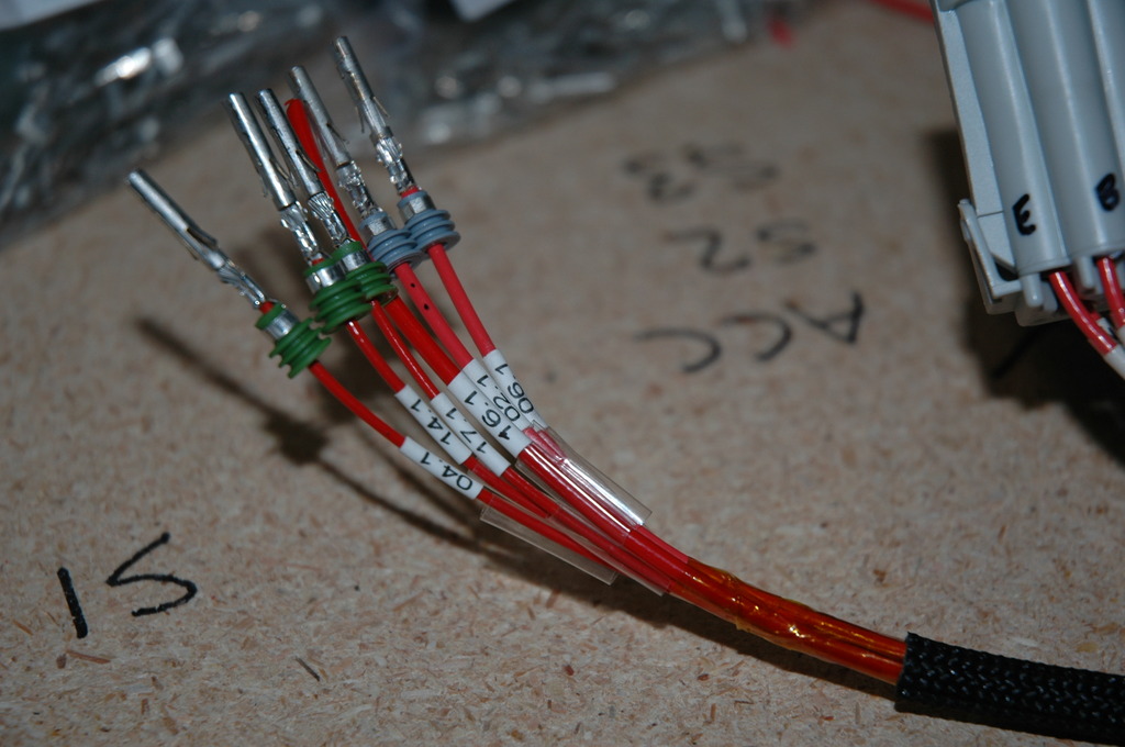
Here was my starting point, the electrical diagram for my new chassis wiring:
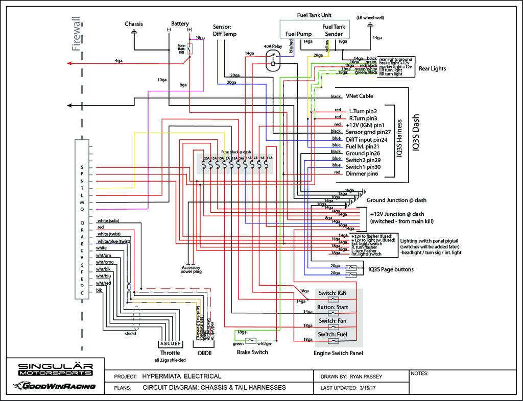
A diagram like this is the bare minimum to plan out a harness. But as soon as you go down this path, if there's an issue in the future you can't just open up a factory service manual to check the wiring diagram. None of that applies any more. The ease or difficulty of service/troubleshooting in the future now comes down entirely to the quality of the documentation you create. With that in mind, I took things a few steps further.
Working off the electrical diagram, I made a spreadsheet listing each individual wire that would be present in the harness - including the wire's name/purpose and where each end terminates. Each wire is assigned a unique numerical ID. If you've ever tried to identify a certain wire in a harness you'll know the struggle that can be - even with the multitude of wire colors that factories use you still end up with duplicates of certain colors and you end up having to break out the multimeter to test wires and sort out what's what. By assigning each wire a unique ID and labeling the wire accordingly (more on that later) there is no guesswork left to do, just consult the master sheet and look up the wire number.
Here's a screenshot of the top of the list. All in, there's about 100 wires on the chassis side:
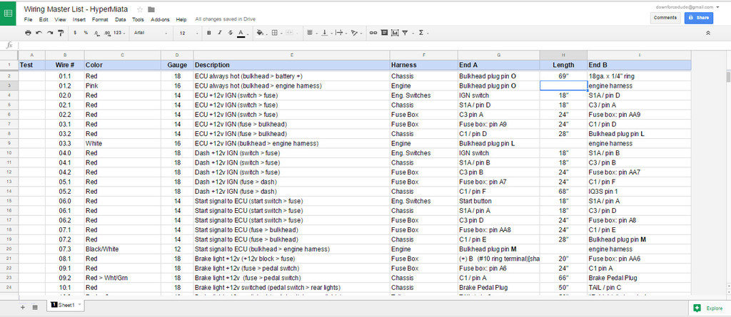
A great feature with having this in spreadsheet form means that if you stay consistent with the info you put in each cell then once the list is done you can sort the list alphabetically by whichever column you need. This was really handy during the build as I could easily switch between sorting by harness, numerical order, system, etc.
The remaining piece to the puzzle is knowing how to lay out the harness. The simplest method is to just start laying wires in the car from point A to B to get lengths, but I wanted to be able to build the harness out of the car and also have the plans so that everything is replicable in the future if necessary.
I took measurements on the car and then drew up the build plans:
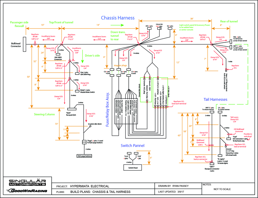
Now, much of the above is a bit overkill. The key info there is the lengths between splits and the layout. The rest isn't necessary but I like to be thorough - with this plus the connector diagrams that I show just a bit further down, I could build a matching replacement harness without any need to refer to the car or the original harness.
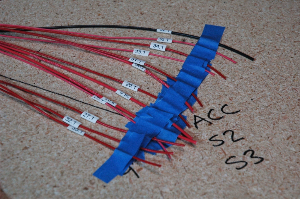
With the planning sorted it was time to start laying out the harness. I transferred the measurements to a 4'x8' sheet of particle board with screws placed at each branch split for turning points. Progress shot with the chassis and tail wires being laid out:
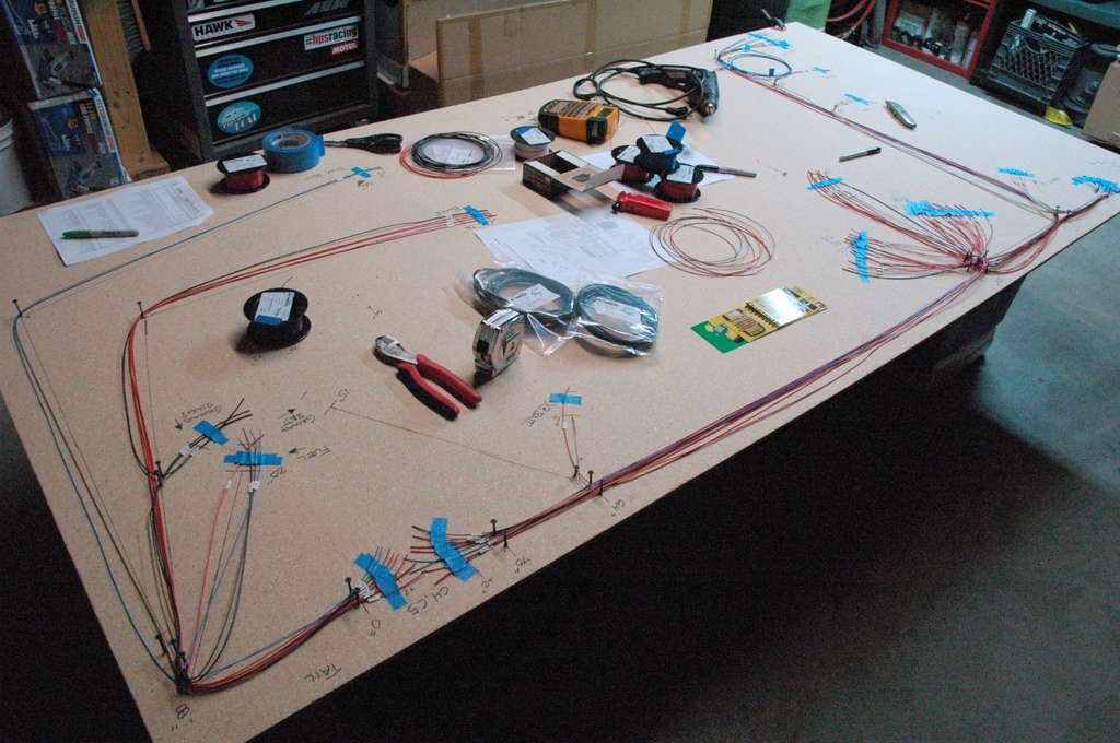
The wires are labeled with their ID number on both ends. Here is where the thermal label printer got a workout:
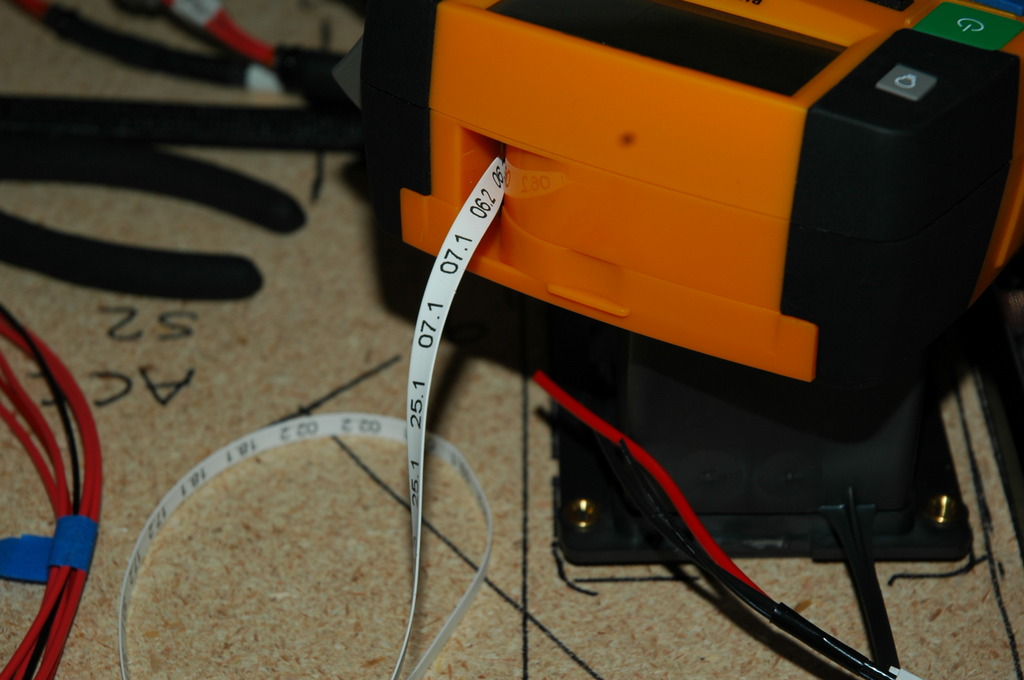
All of the wires used are milspec /32 series with tin plating and very abrasion/temperature resistant insulation. This stuff is a big jump forward from standard cross-link OE wire in terms of durability and is also more conductive and lighter weight. It sounds obvious but the wire is the core of the car's electonics and nothing else can make up for poor quality wire. IMO this isn't the place to scrimp.
Most of the materials for this build came from ProwireUSA. Excellent source for professional/milspec wiring materials and the staff is very knowledgeable. They're local to me but on the other side of town so I can attest to them doing a great job with order processing/shipping times as well.
With all the wires laid out the next step is looming things together. Time for some more materials! Here is all of the shrink tubing used in this build, in several various diameters.
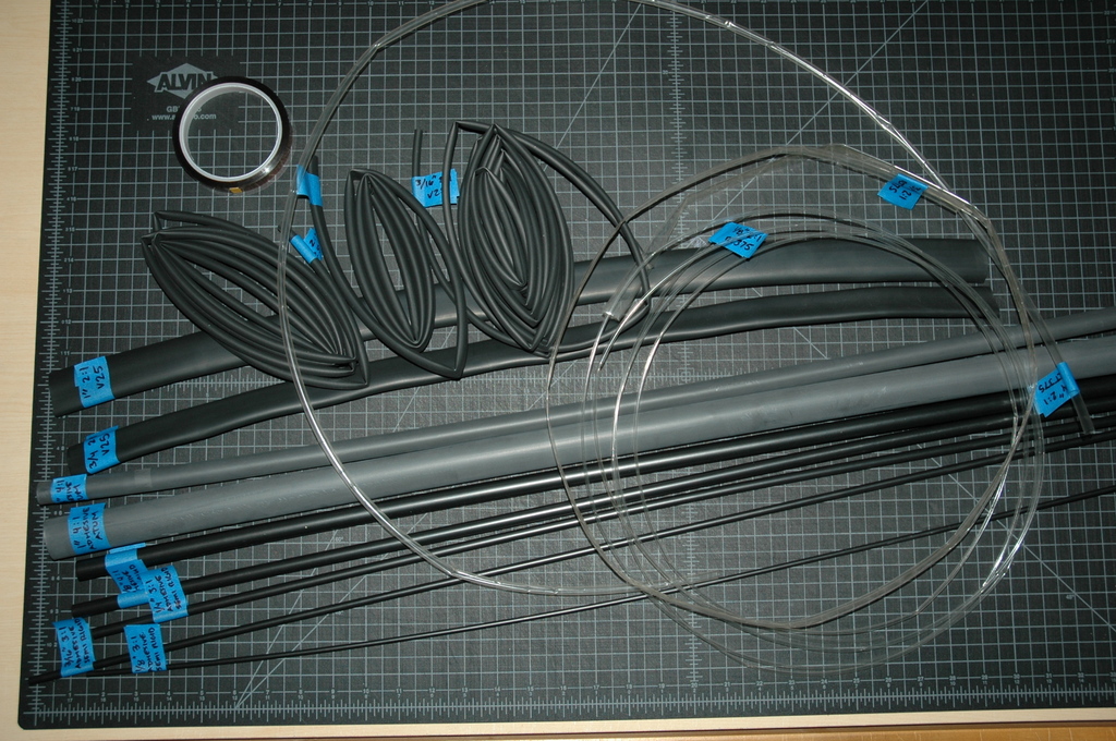
Pictured:
Raychem RT-375; the clear stuff, for covering all the labels.
Raychem SCL; 3:1 shrink ratio, semi-rigid and adhesive lined for sealing bare crimps and also providing strain relief.
Raychem ATUM; massive 4:1 shrink ratio, adhesive lined and flexible
Deray V25; 2:1 shrink ratio, non-adhesive. This is similar to Raychem DR-25 but is a thinner (lighter) version designed specifically for motorsports.
Kapton tape (upper left); super high-heat resistant tape for wiring assembly. Serves as a barrier between the wires and the adhesive shrink tube so if you need to service the harness later you can cleanly cut the tube and tape off and you have like-new wire underneath.
Everything is tagged with its specs. You don't want to accidentally use an adhesive lined tube where you don't want it.
NOT pictured above is another loom material that I used in a lot of areas; resin infused braided fiberglass loom. It’s resistant to chemicals and can withstand a massive 1200� F. That’s quadruple what the good heat shrink tube can take, so this was my choice for the bulk of the chassis harness that runs along the trans tunnel and firewall. Overkill? Yep. I weighed the shrink tube vs. fiberglass loom and they are even, there’s no weight penalty for using either one over the other, except in cases of a run of just one or two wires where there is shrink tube available in smaller diameters than the smallest fiberglass loom. For wire runs of �” diameter and up it’s a wash.
Where to begin?? Fair warning, this is going to be lengthy. I'll have to cut this down and simplify for some of the other forums but here I’ll post all the details.
For the engine swap, the minimum wiring to get the thing fired up isn't bad, particularly if you opt to have V8R prep the engine harness for you (I did). You could certainly retain most of the factory wiring on the chassis side and just tie in where needed.
However... I had a few things on the wish list for this car that meant there was more work to do.
Over the years of racing and modifying this car, the wiring has become a bit of a mess with things added, wiring cut to remove things, etc. etc. There's even been a couple times in the past that I went to modify or fix something in the wiring and found it wasn't the way the FSM says it should be - I had modified it at some distant time in the past and now I couldn't remember how or why I did it.
To eliminate any potential for issues for the future, I decided the best approach was to remove all of the existing wiring on the chassis side from the car and start from scratch with good materials, practices, and documentation. This is also the most time consuming approach, but c'est la vie.
Step 1 through 10 of a big wiring project is all planning, long before any tools or wires come out. Drawing up plans, thinking about the systems you want to include and things you may want to incorporate in the future.
Here was my starting point, the electrical diagram for my new chassis wiring:
A diagram like this is the bare minimum to plan out a harness. But as soon as you go down this path, if there's an issue in the future you can't just open up a factory service manual to check the wiring diagram. None of that applies any more. The ease or difficulty of service/troubleshooting in the future now comes down entirely to the quality of the documentation you create. With that in mind, I took things a few steps further.
Working off the electrical diagram, I made a spreadsheet listing each individual wire that would be present in the harness - including the wire's name/purpose and where each end terminates. Each wire is assigned a unique numerical ID. If you've ever tried to identify a certain wire in a harness you'll know the struggle that can be - even with the multitude of wire colors that factories use you still end up with duplicates of certain colors and you end up having to break out the multimeter to test wires and sort out what's what. By assigning each wire a unique ID and labeling the wire accordingly (more on that later) there is no guesswork left to do, just consult the master sheet and look up the wire number.
Here's a screenshot of the top of the list. All in, there's about 100 wires on the chassis side:
A great feature with having this in spreadsheet form means that if you stay consistent with the info you put in each cell then once the list is done you can sort the list alphabetically by whichever column you need. This was really handy during the build as I could easily switch between sorting by harness, numerical order, system, etc.
The remaining piece to the puzzle is knowing how to lay out the harness. The simplest method is to just start laying wires in the car from point A to B to get lengths, but I wanted to be able to build the harness out of the car and also have the plans so that everything is replicable in the future if necessary.
I took measurements on the car and then drew up the build plans:
Now, much of the above is a bit overkill. The key info there is the lengths between splits and the layout. The rest isn't necessary but I like to be thorough - with this plus the connector diagrams that I show just a bit further down, I could build a matching replacement harness without any need to refer to the car or the original harness.
With the planning sorted it was time to start laying out the harness. I transferred the measurements to a 4'x8' sheet of particle board with screws placed at each branch split for turning points. Progress shot with the chassis and tail wires being laid out:
The wires are labeled with their ID number on both ends. Here is where the thermal label printer got a workout:
All of the wires used are milspec /32 series with tin plating and very abrasion/temperature resistant insulation. This stuff is a big jump forward from standard cross-link OE wire in terms of durability and is also more conductive and lighter weight. It sounds obvious but the wire is the core of the car's electonics and nothing else can make up for poor quality wire. IMO this isn't the place to scrimp.
Most of the materials for this build came from ProwireUSA. Excellent source for professional/milspec wiring materials and the staff is very knowledgeable. They're local to me but on the other side of town so I can attest to them doing a great job with order processing/shipping times as well.
With all the wires laid out the next step is looming things together. Time for some more materials! Here is all of the shrink tubing used in this build, in several various diameters.
Pictured:
Raychem RT-375; the clear stuff, for covering all the labels.
Raychem SCL; 3:1 shrink ratio, semi-rigid and adhesive lined for sealing bare crimps and also providing strain relief.
Raychem ATUM; massive 4:1 shrink ratio, adhesive lined and flexible
Deray V25; 2:1 shrink ratio, non-adhesive. This is similar to Raychem DR-25 but is a thinner (lighter) version designed specifically for motorsports.
Kapton tape (upper left); super high-heat resistant tape for wiring assembly. Serves as a barrier between the wires and the adhesive shrink tube so if you need to service the harness later you can cleanly cut the tube and tape off and you have like-new wire underneath.
Everything is tagged with its specs. You don't want to accidentally use an adhesive lined tube where you don't want it.
NOT pictured above is another loom material that I used in a lot of areas; resin infused braided fiberglass loom. It’s resistant to chemicals and can withstand a massive 1200� F. That’s quadruple what the good heat shrink tube can take, so this was my choice for the bulk of the chassis harness that runs along the trans tunnel and firewall. Overkill? Yep. I weighed the shrink tube vs. fiberglass loom and they are even, there’s no weight penalty for using either one over the other, except in cases of a run of just one or two wires where there is shrink tube available in smaller diameters than the smallest fiberglass loom. For wire runs of �” diameter and up it’s a wash.
Reply
6
6
03-18-2017, 06:12 AM
#487
Supporting Vendor
Thread Starter
iTrader: (3)
Join Date: Jul 2006
Location: San Diego
Posts: 3,303
Total Cats: 1,216
PART 2
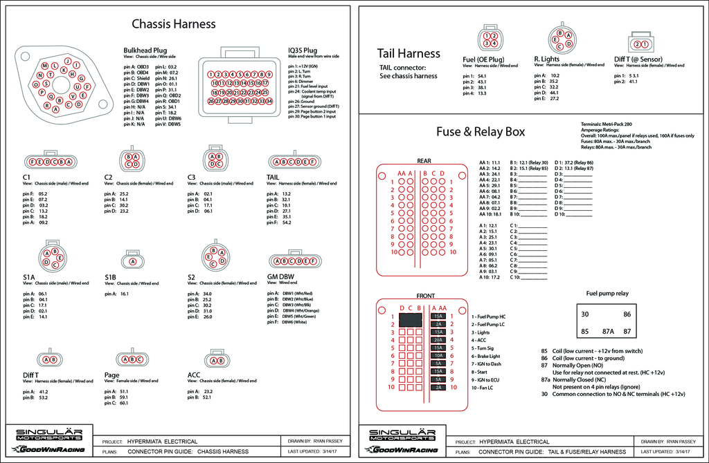
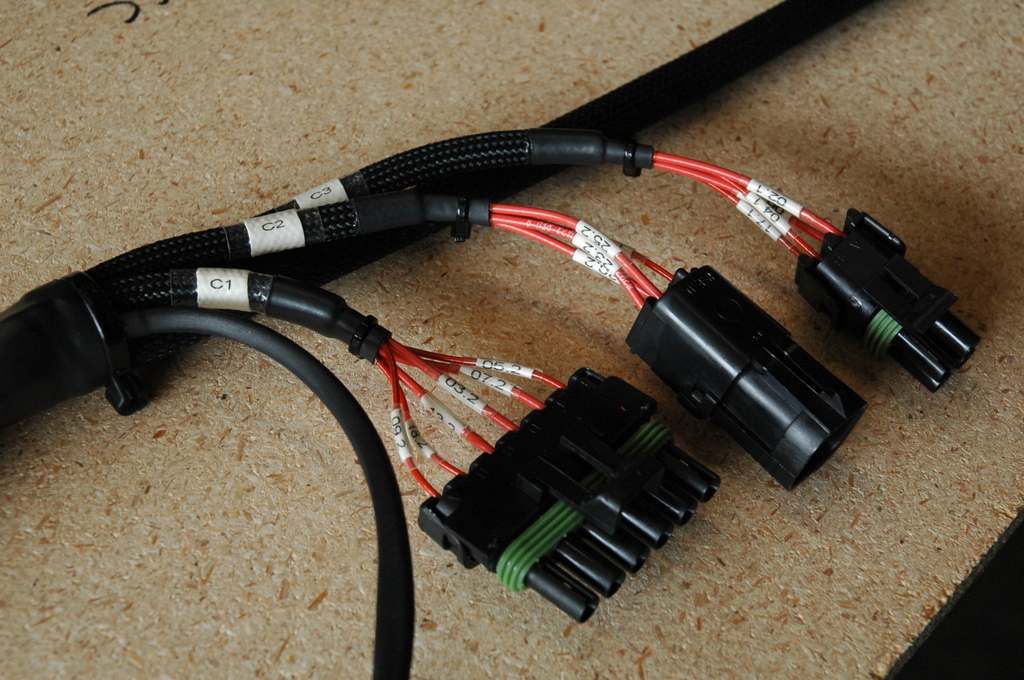
Here I’m beginning to loom the harness with a combination of the fiberglass braid plus short lengths of adhesive tube that will later be shrunk down over the ends of the loom to prevent fraying and seal the wires where the harness splits. You can see that assembling the loom requires a good bit of forward-thinking because each section often needs several more various pieces sleeved over it that will be shrunk down later:
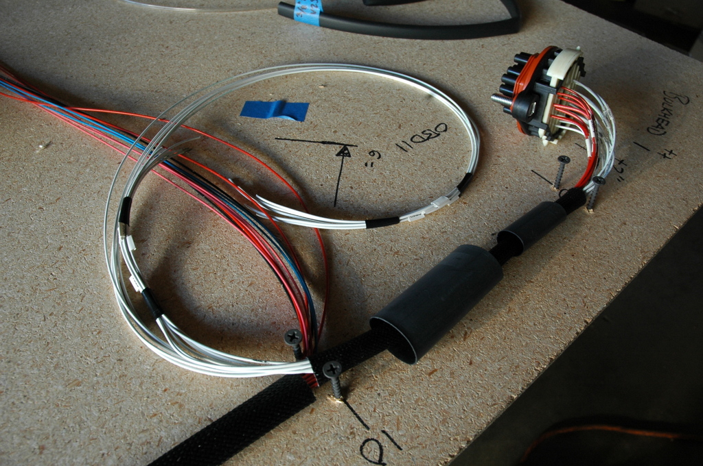
Also in that pic is the bulkhead connector already assembled. That connector contains each wire that will pass from through the firewall into the engine bay, which makes it very quick and easy to disconnect the engine side of the wiring from the car so the engine can be pulled quickly without having to disconnect the wiring harness from the engine.
With beginning to pin wires into connectors we can cover the final piece of documentation; diagrams and pin layouts for each connector in the harness. When I began the harness build this sheet had blank spaces next to each pin, and I filled the sheet out as I assembled connectors:
Looming an engine harness is rather straight-forward as nearly every wire begins at a common datum (usually the ECU). Looming a chassis harness can be a bit more complicated since you have wires doing a lot of back-and-forth from switches to fuses to devices etc. In my case, I planned to put the fuse/relay box and a distribution block for power and ground on the passenger side of the transmission tunnel for easy accessibility. Also along this same area of the harness I had multiple breakouts for connectors that would go to the switch panel. This all made for a dense bunch of splits all at one point requiring a bit of work to tidy up and seal.
Here the wire is as condensed as possible and wrapped in kapton tape, ready for the Raychem ATUM to be slid over and shrunk to seal the breaks:
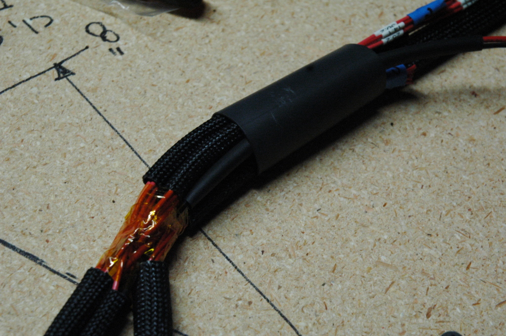
And with the breaks all sealed up:
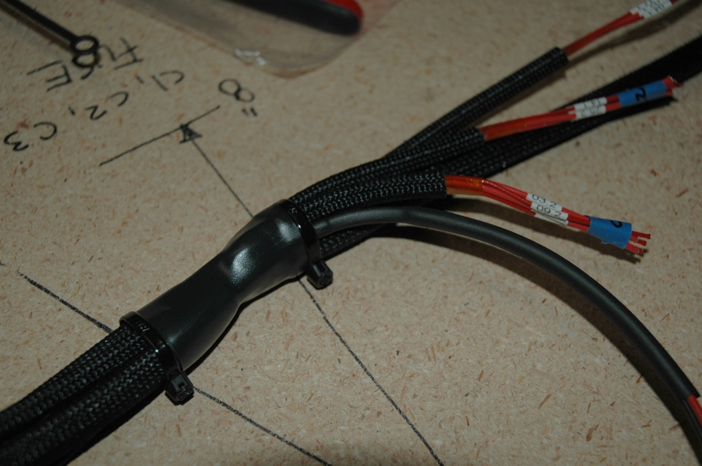
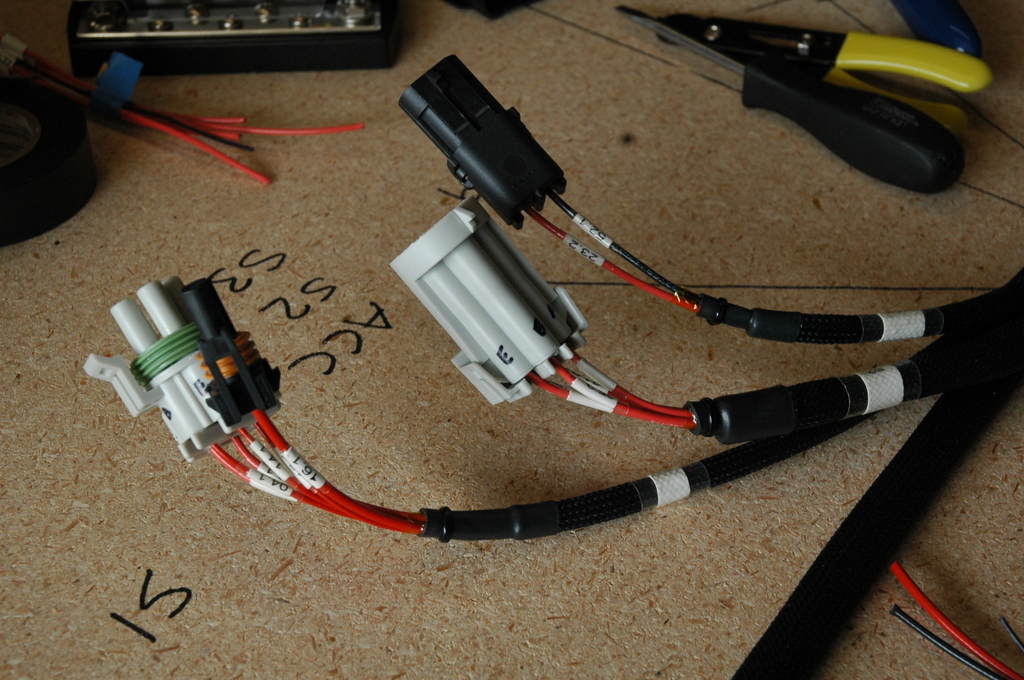
After the loom is in place the last step is pinning the wires for the connectors. There are a few popular options for connectors with different strengths. I chose to use the common weatherpack and metri pack connectors for ease of service. Each wire has a seal that is assembled with the terminal so that the wire itself seals to the connector - the benefit here is this eliminates the need to seal the whole backside of the connector. In this pic you can also see the short sections of clear shrink tube that are put on each wire before the terminal is crimped on and will be shrunk over the labels afterwards:
Terminals inserted into connectors, connector sheet updated with which wire went in which pin position and each connector’s name labeled on the loom behind it. These are the connectors that go to all the engine and auxillary control switches that will be on the center console:
Similarly finished ends that go to the fuse/relay box:
There were a few other connector types used for the harness as well. Some were OEM connectors that had to be re-used, and then there was the connector that goes to the Racepack IQ3S dash. This is supplied by Racepack with an extra long pigtail made up of standard cross-link wire. I needed to de-pin the connector and then rewire it with the milspec stuff:
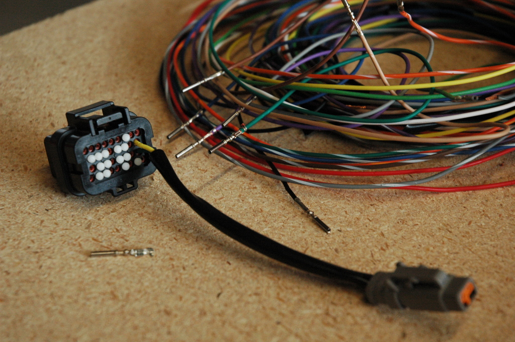
After some digging I found this is a Motec M800 34-pin connector. What do you know, ProwireUSA has pins for those
Here’s the connector, new and improved:
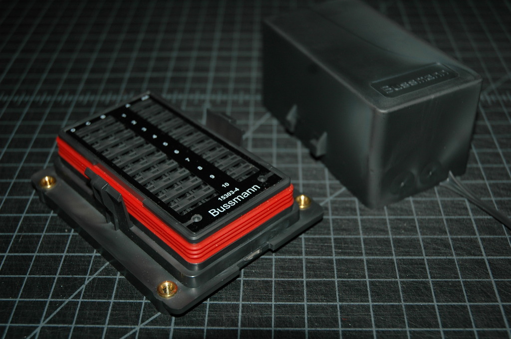
For fuses and relays I chose this trick little combo box that takes both mini fuses and micro 280 relays. It uses metri pack seals and connectors:
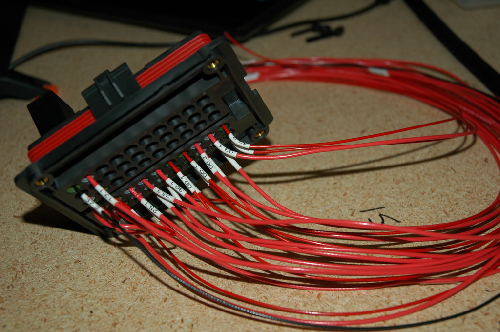
Beginning to wire the box:
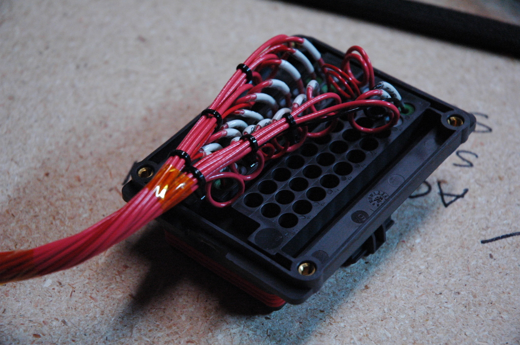
After much work, here it’s tidied up with service/strain relief loops on each wire:
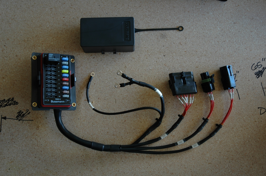
The finished fuse/relay box and harness. The ring terminals go to a bus bar for power distribution and grounds. I put this whole assembly on connectors rather than build it into the harness so that it can be removed for service or additions without the need to take the whole main harness out of the car:
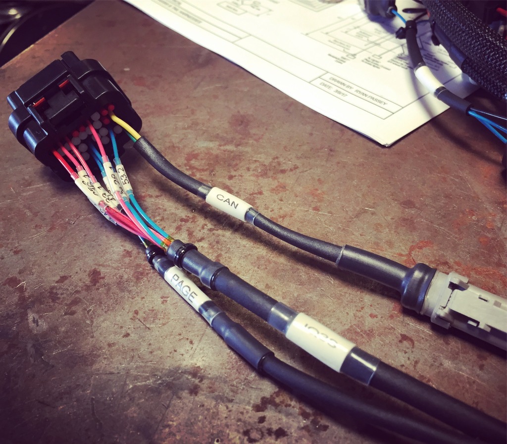
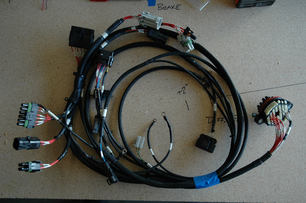
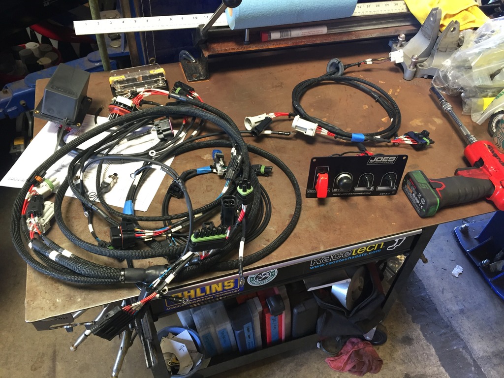
And after much more work, we’ve got finished harnesses, ready to go to the shop for install.
Main chassis harness (connectors to Racepack dash, OE brake pedal , GM gas pedal, fuses/relays, OBDII, all switches, tail harness, diff temp sensor harness) :
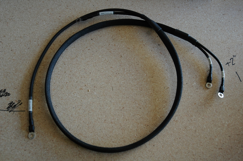
Power and ground to bus bars:
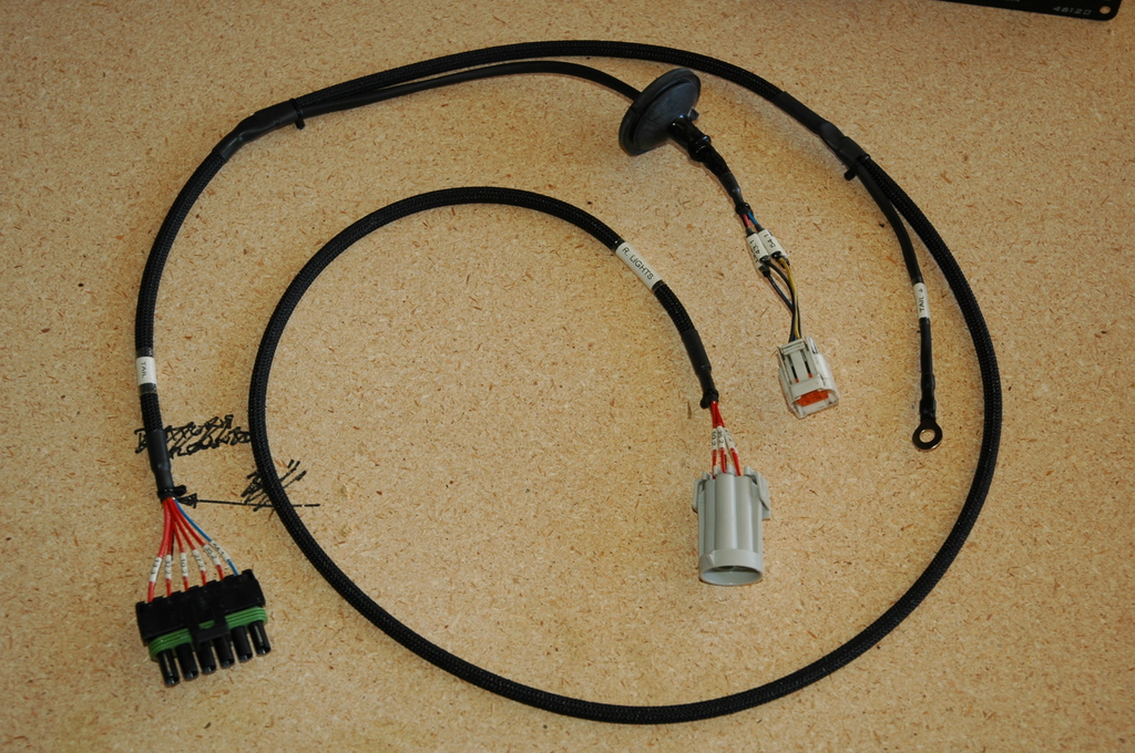
Tail harness (connectors to chassis harness to fuel tank, rear lights, and grounds):
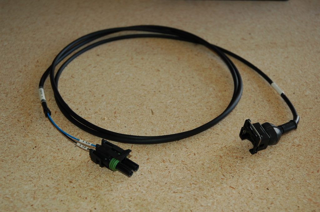
Diff temperature sensor harness:
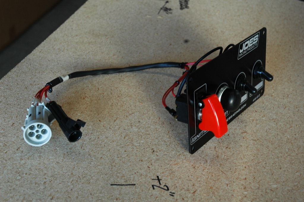
Engine control switches:
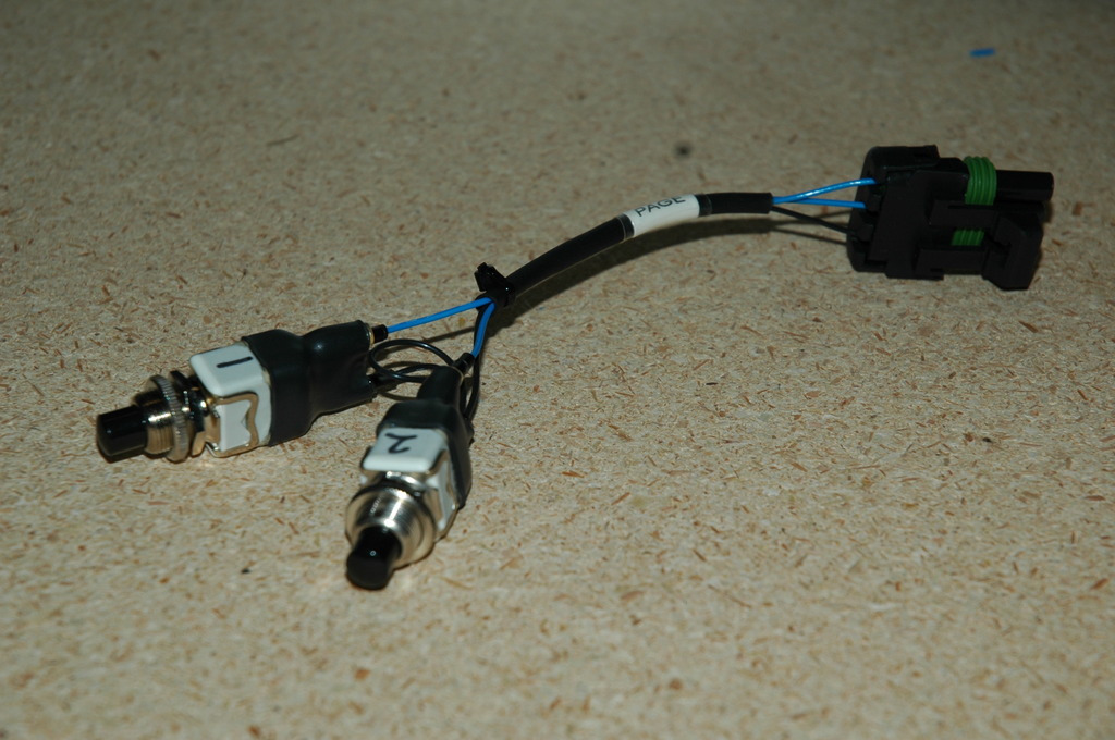
Racepack dash page toggle buttons:
At the shop, everything ready to go in. Oh, and this saves 10 lbs over the old wiring that was the already hacked and trimmed down factory harness:
The last couple days I’ve been installing the wiring and tying in the engine side of the wiring. Pics to come.
Here I’m beginning to loom the harness with a combination of the fiberglass braid plus short lengths of adhesive tube that will later be shrunk down over the ends of the loom to prevent fraying and seal the wires where the harness splits. You can see that assembling the loom requires a good bit of forward-thinking because each section often needs several more various pieces sleeved over it that will be shrunk down later:
Also in that pic is the bulkhead connector already assembled. That connector contains each wire that will pass from through the firewall into the engine bay, which makes it very quick and easy to disconnect the engine side of the wiring from the car so the engine can be pulled quickly without having to disconnect the wiring harness from the engine.
With beginning to pin wires into connectors we can cover the final piece of documentation; diagrams and pin layouts for each connector in the harness. When I began the harness build this sheet had blank spaces next to each pin, and I filled the sheet out as I assembled connectors:
Looming an engine harness is rather straight-forward as nearly every wire begins at a common datum (usually the ECU). Looming a chassis harness can be a bit more complicated since you have wires doing a lot of back-and-forth from switches to fuses to devices etc. In my case, I planned to put the fuse/relay box and a distribution block for power and ground on the passenger side of the transmission tunnel for easy accessibility. Also along this same area of the harness I had multiple breakouts for connectors that would go to the switch panel. This all made for a dense bunch of splits all at one point requiring a bit of work to tidy up and seal.
Here the wire is as condensed as possible and wrapped in kapton tape, ready for the Raychem ATUM to be slid over and shrunk to seal the breaks:
And with the breaks all sealed up:
After the loom is in place the last step is pinning the wires for the connectors. There are a few popular options for connectors with different strengths. I chose to use the common weatherpack and metri pack connectors for ease of service. Each wire has a seal that is assembled with the terminal so that the wire itself seals to the connector - the benefit here is this eliminates the need to seal the whole backside of the connector. In this pic you can also see the short sections of clear shrink tube that are put on each wire before the terminal is crimped on and will be shrunk over the labels afterwards:
Terminals inserted into connectors, connector sheet updated with which wire went in which pin position and each connector’s name labeled on the loom behind it. These are the connectors that go to all the engine and auxillary control switches that will be on the center console:
Similarly finished ends that go to the fuse/relay box:
There were a few other connector types used for the harness as well. Some were OEM connectors that had to be re-used, and then there was the connector that goes to the Racepack IQ3S dash. This is supplied by Racepack with an extra long pigtail made up of standard cross-link wire. I needed to de-pin the connector and then rewire it with the milspec stuff:
After some digging I found this is a Motec M800 34-pin connector. What do you know, ProwireUSA has pins for those
Here’s the connector, new and improved:
For fuses and relays I chose this trick little combo box that takes both mini fuses and micro 280 relays. It uses metri pack seals and connectors:
Beginning to wire the box:
After much work, here it’s tidied up with service/strain relief loops on each wire:
The finished fuse/relay box and harness. The ring terminals go to a bus bar for power distribution and grounds. I put this whole assembly on connectors rather than build it into the harness so that it can be removed for service or additions without the need to take the whole main harness out of the car:
And after much more work, we’ve got finished harnesses, ready to go to the shop for install.
Main chassis harness (connectors to Racepack dash, OE brake pedal , GM gas pedal, fuses/relays, OBDII, all switches, tail harness, diff temp sensor harness) :
Power and ground to bus bars:
Tail harness (connectors to chassis harness to fuel tank, rear lights, and grounds):
Diff temperature sensor harness:
Engine control switches:
Racepack dash page toggle buttons:
At the shop, everything ready to go in. Oh, and this saves 10 lbs over the old wiring that was the already hacked and trimmed down factory harness:
The last couple days I’ve been installing the wiring and tying in the engine side of the wiring. Pics to come.
Last edited by ThePass; 03-20-2017 at 06:05 PM.
Reply
14
14
03-18-2017, 07:20 AM
#488

That brings back memories of designing manufacturing test fixtures. There is something so satisfying about building a complex cable harness and then plugging it in and it just works. What do you use for your cable drawings?
I second using excel for a wire list, it is more important than the block diagram schematic. Once the assembly is installed, the wire list is way easier to follow when troubleshooting and the wires are labeled. Just an FYI to the diy crowd, you can use a regular thermal label printer and clear shrink wrap.
I second using excel for a wire list, it is more important than the block diagram schematic. Once the assembly is installed, the wire list is way easier to follow when troubleshooting and the wires are labeled. Just an FYI to the diy crowd, you can use a regular thermal label printer and clear shrink wrap.
Reply
0
0


 03-20-2017, 05:07 PM
#494
Supporting Vendor
Thread Starter
iTrader: (3)
Join Date: Jul 2006
Location: San Diego
Posts: 3,303
Total Cats: 1,216
Nah, the box is available bussed but I just couldn't decide on what I wanted on that front and decided to wire individually. Gives me the most flexibility on how I use the box anyways.
Reply
0
0
 03-20-2017, 11:14 PM
#496
Supporting Vendor
Thread Starter
iTrader: (3)
Join Date: Jul 2006
Location: San Diego
Posts: 3,303
Total Cats: 1,216
It occurs to me that I should point out; the wiring diagrams etc. that I've posted are intended as examples and inspiration only, there's no short-cutting the necessary work of planning the electrical needs of one's own car and developing their own wiring plan for it. I can only promise that my plans work for my own car, not for yours. 
Reply
0
0
03-21-2017, 12:16 PM
#497
this is just ****.
__________________
OG Racing
Your Source For Motorsports Safety Equipment
WWW.OGRACING.COM
800.934.9112
703.430.3303
info@ogracing.com
OG Racing
Your Source For Motorsports Safety Equipment
WWW.OGRACING.COM
800.934.9112
703.430.3303
info@ogracing.com
Reply
0
0
03-21-2017, 12:55 PM
#498
Junior Member

Join Date: Jan 2007
Posts: 230
Total Cats: -23
Absolutely amazing work Ryan! I've always lusted after trick race car hardware including wiring harnesses. That is the way I've always wished I could do my wiring. Half way through my own Megasquirt project I was wishing I had just built my own engine harness. But I know it won't be feasible for quite some time due to other commitments. When I was young I had the free time but no money and the car was my daily driver so I couldn't afford the downtime. Now that I'm older and the Miata is a pleasure vehicle I have the money but not the free time. I could always outsource it, but this is something that very few shops do and do competently. Those that do usually have a long waiting list and time is money. It's easy to spend $20k or more on an ECU (Motec), dash/datalogger, wiring harness combo. The Honda community has some brave souls who can use economy of scale to do this kind of stuff a little bit cheaper but it's still not cheap.
Reply
0
0


