Ducting and airflow
 07-20-2009, 05:16 AM
#21
Former Vendor

Thread Starter
iTrader: (31)

Join Date: Nov 2006
Location: Sunnyvale, CA
Posts: 15,442
Total Cats: 2,099
Side ducts. It'll give me as much as possible to the radiator.
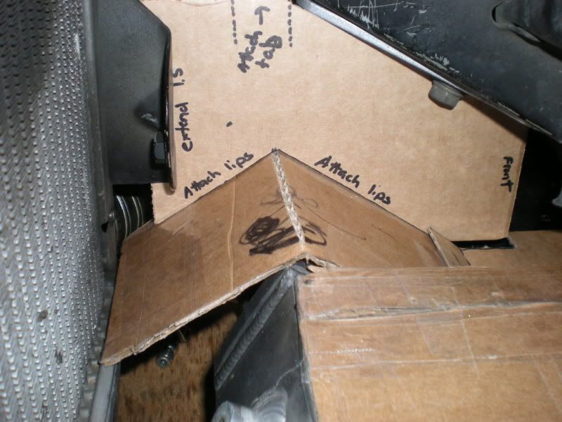
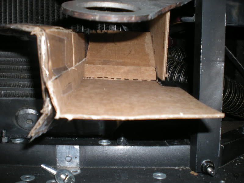
I am going to be using sheet aluminum (forgot how thick, like .050ish) and rivets to actually build all this stuff. hardest part will be doing stuff in as few pieces as possible, and getting all the little stuff right (mounting tabs and stuff).
I am going to be using sheet aluminum (forgot how thick, like .050ish) and rivets to actually build all this stuff. hardest part will be doing stuff in as few pieces as possible, and getting all the little stuff right (mounting tabs and stuff).

Reply
 0
0

0
07-20-2009, 09:14 AM
#22
IMO that will work as good as it could. This isn't far from what AIM tuning did on their time trial turbo Miata. The only improvement would be in cruves vs. the straight off angles. Harsh angles create a ramp launching the air vs. providing a contoured surface for it follow and encourage expansion. Same stuff you see on all the prototype cars - and stock cars as documented in this article. Graphic from article:

I think there's a reason you see 800hp cars running 24hour races with a full body and not over heating. They focus not on the size of the inlet nearly as much as the exit of the air and what happens to the air after it's passed the inlet. In general, I agree that enlarging the inlet may show improvements over stock, but would arguing that it's not nearly as efficient as improving other aspects - like extracting or sealing up the mouth or reforming the interior of the OE mouth...
Something to consider per your oil cooler feed too- that air will be exiting into the area that contains the high pressure for feeding your rad. So you'll be fighting a pressure differential at that point from the air exiting your oil cooler vs. the air trying to pass through the rad. You might only drill two holes, bring the hold saw to the track and see what happens, drilling more holes as needed. Or devise a means for blocking the oil cooler holes (racers tape?).
Reply
0
0
07-20-2009, 10:10 AM
#24
Moderator

iTrader: (12)
Join Date: Nov 2008
Location: Tampa, Florida
Posts: 20,646
Total Cats: 3,009
What you are creating is something I have been mulling over for a few weeks as well (no, I'm not turbo'd, but studying and planning still). You have created a Vmount setup in this configuration, just with the IC on the bottom instead of the top where most people's end up. The hot air leaving the IC will not be a factor in your radiator's cooling capability anymore and neither will the restriction of forcing air through the intercooler before allowing it to the radiator. The low pressure area behind the IC and the radiator created by the splitter and your well-sealed ducting will ensure plenty of pull through both heat exchangers. I see it as a win.
If you saw fit, you could move, seal, and duct the oil cooler so that it's hot air exits through the opening between the leading edge of the hood and the top of the core support (where the filler panel is by the hood latch) and goes over the rad, just like the IC's hot air goes under the rad. Just brainstorming on that one. Good luck.
If you saw fit, you could move, seal, and duct the oil cooler so that it's hot air exits through the opening between the leading edge of the hood and the top of the core support (where the filler panel is by the hood latch) and goes over the rad, just like the IC's hot air goes under the rad. Just brainstorming on that one. Good luck.

Reply
0
0
 07-20-2009, 10:23 AM
#26
Senior Member

Join Date: Sep 2007
Location: Alamo City, Tejas
Posts: 771
Total Cats: 1
- L
Reply
0
0
07-20-2009, 10:41 AM
#29
2 Props,3 Dildos,& 1 Cat

iTrader: (8)
Join Date: Jun 2005
Location: Fake Virginia
Posts: 19,338
Total Cats: 573
and there will be a barrier between the IC and radiator on the top of the IC?
Sav: I wouldn't worry about taking air from under the bumper. it's all going to exit the engine bay under the car anyway.
Reply
0
0
07-20-2009, 01:27 PM
#33
Former Vendor
Thread Starter
iTrader: (31)
Join Date: Nov 2006
Location: Sunnyvale, CA
Posts: 15,442
Total Cats: 2,099
Something to consider per your oil cooler feed too- that air will be exiting into the area that contains the high pressure for feeding your rad. So you'll be fighting a pressure differential at that point from the air exiting your oil cooler vs. the air trying to pass through the rad. You might only drill two holes, bring the hold saw to the track and see what happens, drilling more holes as needed. Or devise a means for blocking the oil cooler holes (racers tape?).
Reply
0
0
07-20-2009, 01:31 PM
#34
Former Vendor
Thread Starter
iTrader: (31)
Join Date: Nov 2006
Location: Sunnyvale, CA
Posts: 15,442
Total Cats: 2,099
I also like the curves. Straight lines are about a thousand times easier to assemble and build, though. Any ideas for attaching the side ducts to the bottom ducts? I was going to just have little bent tabs on the sides and rivet them to the bottom, but I can't do that with curves.
Reply
0
0
 07-20-2009, 05:49 PM
#38
Elite Member

Join Date: Jul 2005
Posts: 6,420
Total Cats: 84
Sav, have you instrumented if your problem is lack of airflow or poor heat transfer from the coolant to the radiator? My guess though, is lack of airflow.
I think the reason why V mounts help, without increasing the frontal hole area, is akin to impedance matching in electronics. When you have a very high airflow velocity the high resistance of the radiator core + i/c core just makes the air pile up in front of the radiator.
I have a theory that during road testing this problem manifests as significantly higher coolant temps at higher cruise speeds (e.g. 75-85 mph) vs. at lower speeds (55-65). This is as opposed to setups which overheat in stop and go traffic.
With V mounting the air spreads out over a larger area, plus the resistance the cores present is reduced (the rad and ic aren't stacked).
This theory is probably also why my AG Bell book "4 stroke performance tuning" suggests that a lower fin density radiator is better for high speed cooling.
As patsmx5 alluded to before, enlarging the frontal hole area of the car is not good, but my theory is not so much because it doesn't improve cooling (it will somewhat), but because the cooling to drag penalty is poor. (big increase for marginal improvement in cooling).
BTW the TDR ic has plastic panels which bend airflow smoothly towards the radiator, along the same lines as m2cupcar's drawing in post #30.
Reply
0
0
07-20-2009, 06:00 PM
#39
Elite Member
iTrader: (15)

Join Date: Dec 2007
Location: San Antonio, Texas
Posts: 4,847
Total Cats: 27
I have a v-mount that I am finishing up right now. I was planning on waiting until I had some road testing in place so I could have some data to back up the design. But, if y'all want to see it I'll post up the picts beforehand.
It is a top-mount v-mount using the stock NB nose. Minimal cutting required for the body, and the framework was easy to fab as well. It is all boxed in (splitter and undertray) so all of the flow coming in the nose is forced through the radiator and IC (and a/c condenser).
It is a top-mount v-mount using the stock NB nose. Minimal cutting required for the body, and the framework was easy to fab as well. It is all boxed in (splitter and undertray) so all of the flow coming in the nose is forced through the radiator and IC (and a/c condenser).
Reply
0
0
07-20-2009, 06:51 PM
#40

I also like the curves. Straight lines are about a thousand times easier to assemble and build, though. Any ideas for attaching the side ducts to the bottom ducts? I was going to just have little bent tabs on the sides and rivet them to the bottom, but I can't do that with curves.
Reply
0
0


