Lets Talk Miata Tach signals
 11-20-2010, 01:31 AM
#1
Elite Member
Thread Starter
iTrader: (12)

Join Date: Nov 2009
Location: Harpers Ferry WV
Posts: 1,516
Total Cats: 20
Ok I have a 92 miata with a inline 6 cyl. I had a shift light hooked up in my car before with no problems and the tach worked before I did the swap. My problem now is trying to figure out what type of signal the miata tach uses and do I need a tach adapter.
My new engine has a distributor and uses a 12V tach signal.
I do not know what type of signal the miata stock tach uses. (92 Miata)
Do I need a tach converter or something to make my tach work with the new engine?
I know the NB has a serial link connector and the ecu converts the signal to an old style 12V before it goes to the tach but is it the same on a NA.
I just need to know what I should do to hook a 12V distributor tach signal to a stock miata tach.
Any help would be great I am really confused on this one.

Reply
 0
0

0


 11-20-2010, 10:01 PM
#6
Junior Member

Join Date: Mar 2010
Location: onion city,ca
Posts: 413
Total Cats: 2
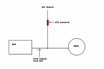
i had same problem adapting my nissan sr20det to aim dash. sr20 output 0-5v square. aim wants 0-12v. i used a smallish pullup resister (47k) to fix. i watched the waveform on the scope and 47k was enough to give nice 0-12v square wave. i didn't want to go too low ohms so as not to pull too much current through the sr20 ecu. i would guess same applies to the toyota ecu.
Reply
0
0
11-20-2010, 10:46 PM
#7
Elite Member
Thread Starter
iTrader: (12)
Join Date: Nov 2009
Location: Harpers Ferry WV
Posts: 1,516
Total Cats: 20
Ok I just thought of something as well. The signal out of the ecu is a 5v but if I pick up my tach signal off the gound terminal of the coil and see if that works if not MSD makes a tach adapter I can pick up used for like $35 and I will go that route. I would try putting in a resistor but I do not have a scope I can look at the signal with. That would make this a whole lot easier.
Reply
0
0
11-21-2010, 11:22 AM
#9
Elite Member
Thread Starter
iTrader: (12)
Join Date: Nov 2009
Location: Harpers Ferry WV
Posts: 1,516
Total Cats: 20
Ok I will try that first I imagine it will work. I will see if I can pick up a 47K pullup resistor next week and see if that works. Thanks for the input
Reply
0
0
11-22-2010, 09:29 AM
#10
Elite Member
Thread Starter
iTrader: (12)
Join Date: Nov 2009
Location: Harpers Ferry WV
Posts: 1,516
Total Cats: 20
Ok so I had the guys at my work help me with the math and its seems to all check out right on the money. Like I said before I do not have a scope but with the math in order and two resistors in hand I think everything will be ok. So after the holidays I will wire it all in and see how it works.
jasonb- thank you for your help I think you just saved me $80 by not ordering the autometer adapter.
jasonb- thank you for your help I think you just saved me $80 by not ordering the autometer adapter.
Reply
0
0
11-22-2010, 09:52 AM
#11
Elite Member
Thread Starter
iTrader: (12)
Join Date: Nov 2009
Location: Harpers Ferry WV
Posts: 1,516
Total Cats: 20
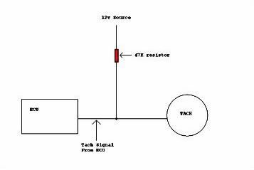
OK last thing until I do it and see if it works here is a super basic drawing of what I am going to do to wire this resistor in can anyone verify that it seems correct or if I am going to do something wrong.
Reply
0
0
11-22-2010, 11:23 AM
#14
Junior Member
Join Date: Mar 2010
Location: onion city,ca
Posts: 413
Total Cats: 2
Originally Posted by kday
I wouldn't use that circuit without knowing more about how the ECU's tach output is implemented.
Reply
0
0
11-22-2010, 11:48 AM
#15
Elite Member
Thread Starter
iTrader: (12)
Join Date: Nov 2009
Location: Harpers Ferry WV
Posts: 1,516
Total Cats: 20
Ok that is what I though and according to what I got it is about .25mV or under 1 watt power returning to the ecu I don't see how this would hurt anything. I am going to check in my book to see the circuit that the tach signal is on but I think it is ok. Now mind you I am not really good on the whole computer internals stuff but I have some really good helpers that say it will be fine as well.
Reply
0
0

Thread
Thread Starter
Forum
Replies
Last Post


