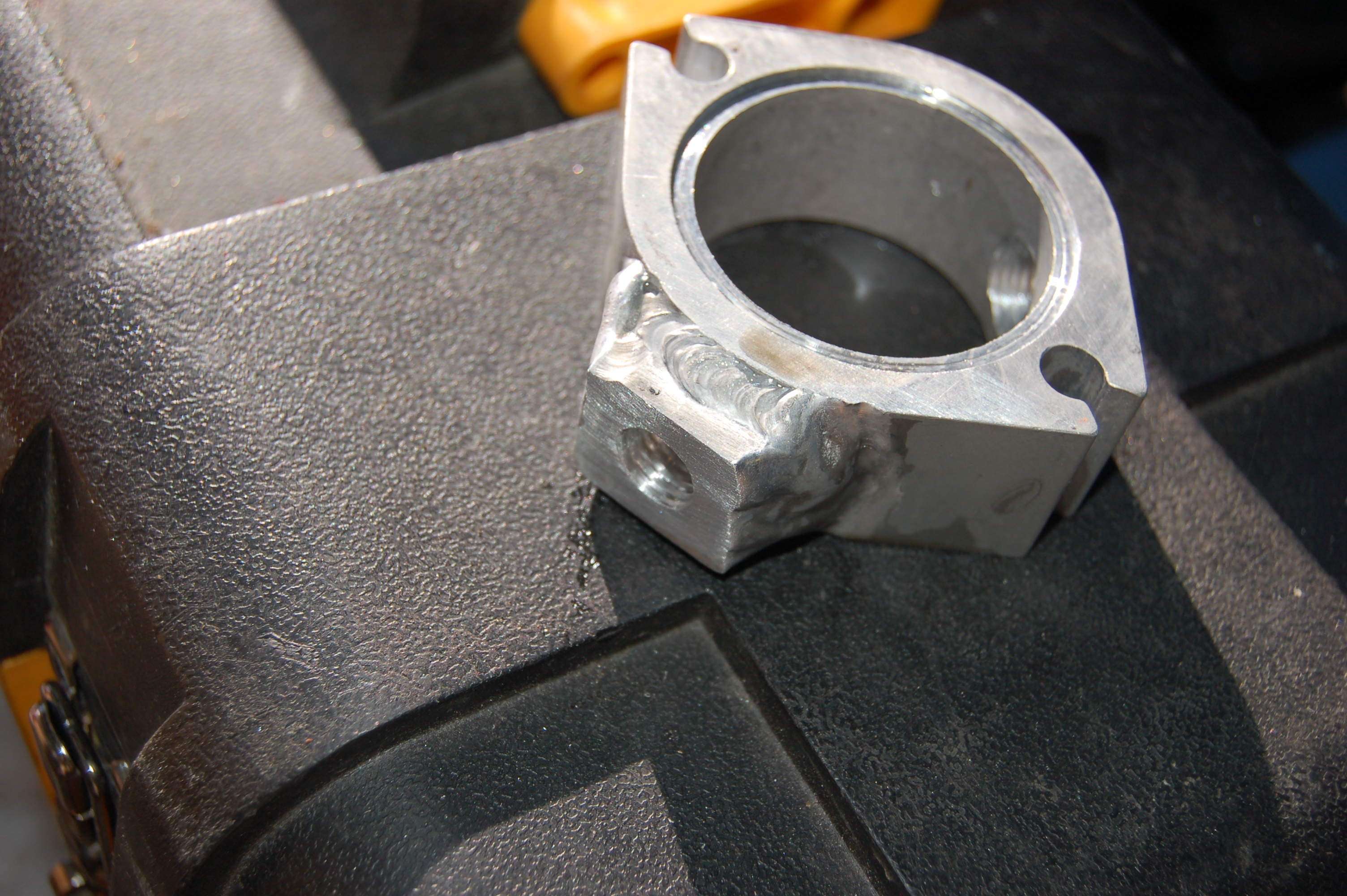
Just showing off my reroute, I know like we need another.
 04-02-2010, 01:18 AM
#1
Elite Member

Thread Starter
iTrader: (11)
Join Date: Apr 2007
Location: VA Beach
Posts: 1,996
Total Cats: 51
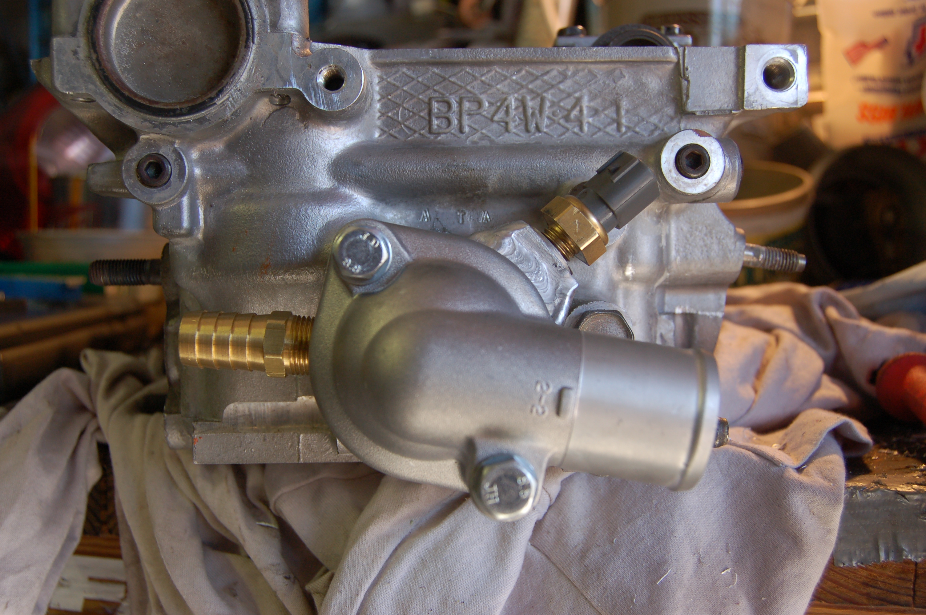
Here some pics of it on my 2000, was a royal PITA but its now done and If I have to say so my self it looks good!


Reply
 0
0

0
04-02-2010, 09:53 AM
#2

Don't forget you ground that spacer to the head as you have now isolated it with gaskets. I just took a male spade connector and rammed it in between the exposed bolt on the top of the spacer and used a ring connector and grounded it on the bolt that holds the bracket across the back of the head (aka the bolt that is missing right above the top bolt of the spacer).
Reply
0
0
 04-02-2010, 10:09 AM
#4

Don't forget you ground that spacer to the head as you have now isolated it with gaskets. I just took a male spade connector and rammed it in between the exposed bolt on the top of the spacer and used a ring connector and grounded it on the bolt that holds the bracket across the back of the head (aka the bolt that is missing right above the top bolt of the spacer).
Reply
0
0
04-02-2010, 10:33 AM
#5
Elite Member
Thread Starter
iTrader: (11)
Join Date: Apr 2007
Location: VA Beach
Posts: 1,996
Total Cats: 51
Don't forget you ground that spacer to the head as you have now isolated it with gaskets. I just took a male spade connector and rammed it in between the exposed bolt on the top of the spacer and used a ring connector and grounded it on the bolt that holds the bracket across the back of the head (aka the bolt that is missing right above the top bolt of the spacer).
Thanks
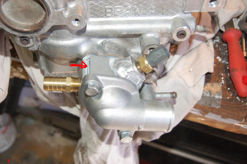
Now your idea might not work either...the bolt is touching the waterneck but not the spacer, there is a gasket in between the spacer and the waterneck.
Hmmmmmm........whats everyone else do?
Reply
0
0
04-02-2010, 10:51 AM
#7
Elite Member
Thread Starter
iTrader: (11)
Join Date: Apr 2007
Location: VA Beach
Posts: 1,996
Total Cats: 51
I bet this would be simpler. What if you you just jammed something in between the bolt and the spacer or wrapped the bolt with something so it touched the spacer. Than the spacer would ground to the bolt.
Reply
0
0
04-02-2010, 12:38 PM
#8
Yeah, you could jam something between the bolt and the spacer since the bolt goes into the head, but I added a grounding wire just to ensure a ground. Logic says the 3-wire sensor has a ground, but I found out for myself the it needs to be grounded to the engine. I did my RR and fought a bouncing temp gauge for a week before finding the solution was to ground the spacer. It almost seems as if the ground wire is for the ECU voltage and the sensor itself being a ground is for the gauge output because when I did data logging to verify temps, they were rock solid when viewed on a laptop but the gauge was still all over the place.
-EDIT NOTE- For everyone else, remember that my car is a 02 and uses the 3-wire temp sensor. I am not sure as to the sensor used on the 94-97 and I knoew this hsould not be an issue on the 90-93.
-EDIT NOTE- For everyone else, remember that my car is a 02 and uses the 3-wire temp sensor. I am not sure as to the sensor used on the 94-97 and I knoew this hsould not be an issue on the 90-93.
Reply
0
0
 04-02-2010, 06:21 PM
#10
Elite Member
Thread Starter
iTrader: (11)
Join Date: Apr 2007
Location: VA Beach
Posts: 1,996
Total Cats: 51
Well good news is the car is running well.
Checked the sensor with a meter and its somehow grounded (must have hit the bolt). So I will leave it as is for now. Think in the future when I remove the coil pack and cam cover I'll just tap a short screw in there and ground a wire to be sure.
Checked the sensor with a meter and its somehow grounded (must have hit the bolt). So I will leave it as is for now. Think in the future when I remove the coil pack and cam cover I'll just tap a short screw in there and ground a wire to be sure.
Reply
0
0

 04-03-2010, 04:13 AM
#13
Senior Member

Join Date: Dec 2004
Location: Brisbane, Australia
Posts: 1,278
Total Cats: 37
Yeah after reading that **** I did the same. Managed to find a big *** ring terminal that would fit over the thread of the temp sensor, and another one for one of the two bolts going into the head. It looks rather silly though cause I'm running 2 gauge wire so it would crimp properly. VERY overkill, more grounding than the rest of the whole engine! 
Reply
0
0
04-03-2010, 12:32 PM
#14
Boost Pope

iTrader: (8)
Join Date: Sep 2005
Location: Chicago. (The less-murder part.)
Posts: 33,025
Total Cats: 6,592
One is the sensor that feeds the ECU. This one has both the signal and ground lines brought out to the connector. The other is the sensor that feeds the gauge on the instrument panel. This one goes to ground through the sensor body.
Schematically, this is identical to the sensor arrangement on all of the NAs, where there were two separate sensors for these functions, with the ECU sensor having two wires (signal and ground) and the one for the gauge having a single wire and grounding through the thread.
Oh, and I'm not aware of ANY temp sensor in an automotive application where 5v ref comes in as a unique signal. On every one I've seen, the current-limited reference gets applied to the signal line inside the ECU. The sensor then forms one half of a voltage divider (the current limiting resistor being the other half) and the resultant voltage between the two is the signal.
Reply
0
0
04-03-2010, 12:56 PM
#15
Elite Member

Join Date: Mar 2006
Location: Schwarzenberg, Germany
Posts: 1,553
Total Cats: 101
Yeah, you could jam something between the bolt and the spacer since the bolt goes into the head, but I added a grounding wire just to ensure a ground. Logic says the 3-wire sensor has a ground, but I found out for myself the it needs to be grounded to the engine. I did my RR and fought a bouncing temp gauge for a week before finding the solution was to ground the spacer. It almost seems as if the ground wire is for the ECU voltage and the sensor itself being a ground is for the gauge output because when I did data logging to verify temps, they were rock solid when viewed on a laptop but the gauge was still all over the place.
-EDIT NOTE- For everyone else, remember that my car is a 02 and uses the 3-wire temp sensor. I am not sure as to the sensor used on the 94-97 and I knoew this hsould not be an issue on the 90-93.
-EDIT NOTE- For everyone else, remember that my car is a 02 and uses the 3-wire temp sensor. I am not sure as to the sensor used on the 94-97 and I knoew this hsould not be an issue on the 90-93.
I have to try this ASAP!
Thanks
Reply
0
0
 04-04-2010, 05:25 PM
#17
Elite Member
Thread Starter
iTrader: (11)
Join Date: Apr 2007
Location: VA Beach
Posts: 1,996
Total Cats: 51
The three-wire sensor on the NB cars is actually two sensors in a single body.
One is the sensor that feeds the ECU. This one has both the signal and ground lines brought out to the connector. The other is the sensor that feeds the gauge on the instrument panel. This one goes to ground through the sensor body.
Schematically, this is identical to the sensor arrangement on all of the NAs, where there were two separate sensors for these functions, with the ECU sensor having two wires (signal and ground) and the one for the gauge having a single wire and grounding through the thread.
Oh, and I'm not aware of ANY temp sensor in an automotive application where 5v ref comes in as a unique signal. On every one I've seen, the current-limited reference gets applied to the signal line inside the ECU. The sensor then forms one half of a voltage divider (the current limiting resistor being the other half) and the resultant voltage between the two is the signal.
But for the moment the dash is working fine so it must have grounded so I ant ******* with it!
Reply
0
0

Thread
Thread Starter
Forum
Replies
Last Post


