
power source at gauge cluster?


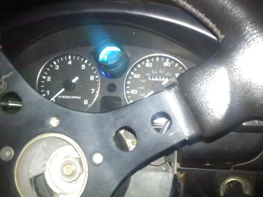
At 6'3" I need all the knee room I can get so I've been using a 300mm momo wheel. Its great for leg room and which a slower manual rack - not too quick. The one issue is my tach is now useless from 5.5K on. I'm not one to use a tach too much but having a visually reference is nice sometimes (ie - when the your vehicle is audibly 'out muscled'). To resolve this I modified my gauge cluster and now have a little LED shift light living behind the smoked plastic window which is used for the e-brake, airbag, etc. warning lights. I want to keep the wires as short as possible and I'm wondering if I can source all the necessary signals at the cluster or not.
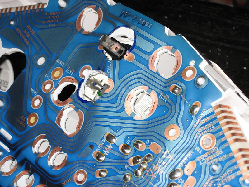
I'm assuming the 'track' marked IGN on the flexible circuit is power (when the key is engaged of course).
Are there any wiring diagrams available for internals of the gauge cluster itself - I'm trying to figure out if I can pick up the tach signal itself so I don't have to go hacking into the harness post-connector.
thanks in advance,
Zach
Reply
 0
0

0

Shift light is cool but maybe you want to look at fixing the tach orientation instead.
http://revlimiter.net/mods/gauges.php
This is from a '93 which is the closest I can get for you. And yes, the IGN is +12V with key engaged. You should be able to intercept that signal from Pin 1H.
http://revlimiter.net/mods/gauges.php
This is from a '93 which is the closest I can get for you. And yes, the IGN is +12V with key engaged. You should be able to intercept that signal from Pin 1H.
Reply
0
0

eh ... if I can't see the speedo needle then I'm breaking the law.
I since I have MS and can data log I don't see much use for the tach aside from using it as a shift reference.
The shift light is in the most prominent area of the gauge cluster and is preferred (by me).
-Zach
I since I have MS and can data log I don't see much use for the tach aside from using it as a shift reference.
The shift light is in the most prominent area of the gauge cluster and is preferred (by me).
-Zach
Reply
0
0
I get that I can rotate both the tach and speedo - point is I don't need or want to. I can see up to 55-65 mph on the speedo - there's really no need for me to know I'm going 90. In fact, down the road i'd like to ditch the speedo and run a central tach with rpm markers for speed because I find I don't really reference it much and I like to keep things simple.
As for the tach, I just can't see the redline and I don't think rotating will help that at all.
I'm going the shift light route for the time being - no more talk of gauge rotation I appreciate the suggestion though.
-Zach
As for the tach, I just can't see the redline and I don't think rotating will help that at all.
I'm going the shift light route for the time being - no more talk of gauge rotation
I appreciate the suggestion though.-Zach
Reply
0
0

what are you going to use to engage the light? And how are you going to adjust the RPM where it is triggered? And also, you may already know this, but LED's require a resistor to drop down the voltage threw the LED. Without the resistor as soon as power is sent to the LED it will destroy it. This is what I did, its an Auto Mete shift light. My cluster is back lite with blue 5 MM LED's. It looks cool at night. Sorry for bad cell pic
Last edited by RyanRaduechel; Nov 22, 2010 at 09:19 PM.
Reply
0
0
It's a packaged shift light ... sorry if the LED part was misleading.
no need for resistors and it has two off the shelf dials to set RPM.
I'll post pictures once it's done ... then it will all make sense.
-Zach
no need for resistors and it has two off the shelf dials to set RPM.
I'll post pictures once it's done ... then it will all make sense.
-Zach
Reply
0
0
Reply
0
0
Reply
0
0
Thanks chris,
I took the tach gauge face off tonight and saw is was indeed the signal I was looking for (they had it marked more clearly than the circuit board).
I really prefer the red back lighting on my MS3 vs. the OEM miata green so while its apart I'm also sanding off the green backer on the faces. Also, the red will be easier to match to my AEM gauges.I just need to figure out what to use as a backer as the lights will be to 'hot' - I'm thinking some translucent white vinyl should do the trick.
I'll post pics when done.
As a side note, if anyone has any AWD gauge rings (the ones with individual lenses) their looking to sell - drop me a line. I'd like to ditch the mono-lense on the OEM cluster.
-Zach
Reply
0
0
for lighting i'm planning on using the EL sheets for even spread. Sanding the green back will cause your gauges to be very bright around the bulbs and dim elsewhere. I did it on my na long back and it looked shitty.
Reply
0
0
mine still has the green, the blue just powers threw it. Its not bright, but the green doesnt really kill out the blue. So it works nicely without having to mess with it too much
Reply
0
0

Thread
Thread Starter
Forum
Replies
Last Post
Zaphod
MEGAsquirt
47
Oct 26, 2018 11:00 PM
StratoBlue1109
Miata parts for sale/trade
21
Sep 30, 2018 01:09 PM


