LED Tachometer
 06-02-2009, 12:31 AM
#1
Elite Member
Thread Starter
iTrader: (7)

Join Date: Jan 2007
Location: Renton Washington
Posts: 1,731
Total Cats: 4
I was looking on youtube today and came across a Shift LED tach that ranged from green-yellow-red. All i can say is I WANT IT! Googled it and saw that FM had one. Flyin' Miata : Interior : Gauges : Shift-I LED tach Hell ya right!? Unfortunately its 170$... I realize that is the best one. Has anyone done a DIY one? I could maybe spend 60-70$ at the most but i dont think i can shell out that much unless i got super serious into tracking/autoX (which is a possibility.) I plan on doing some tracking with my miata as well as AutoX. Just looking for opinions thanks!

Reply
 0
0

0
06-02-2009, 09:26 AM
#2
Boost Pope


iTrader: (8)
Join Date: Sep 2005
Location: Chicago. (The less-murder part.)
Posts: 33,023
Total Cats: 6,591
Googling DIY LED Tachometer produced many hits. A couple of examples:
LED Tachanometer - How-to-Guides & Manuals, scheme, and Tricks (You can substitute a takeoff of one of the ignition trigger lines for the coil of wire.)
http://electronics-diy.com/electroni...tic.php?id=786 (use a regular NPN in place of the PT501)
LED Tachanometer - How-to-Guides & Manuals, scheme, and Tricks (You can substitute a takeoff of one of the ignition trigger lines for the coil of wire.)
http://electronics-diy.com/electroni...tic.php?id=786 (use a regular NPN in place of the PT501)
Reply
0
0
06-02-2009, 11:22 AM
#4
Junior Member
Join Date: Aug 2008
Location: Boston
Posts: 223
Total Cats: 0
Progressive shift lights are way better than analog tachometers. I am really enjoying my home-brew one, and I plan to remove the analog tach entirely to make room for other things, since it is now useless. I have three bright red LEDs in a horizontal line, indicating 5500, 6000, and 6500 RPM, and two really bright blue LEDs which both illuminate at 7000. It is very easy to get right up to but not hit the rev limiter with this setup, and all with peripheral vision.
Reply
0
0
 06-02-2009, 08:18 PM
#6

It's not hard to find the schematics to make one. I was planning to do it years ago before I came across the Revlight. Your cost is going to depend in large part on how many LEDs you use. I like having the full range instead of just 3-4, because it's more useful. At our local track, for example, I can see what my corner exit was like by seeing how many lights are lit up at a certain point. When I started having misfires on the Targa, I knew that as long as I stayed out of the red LEDs I'd be okay.
I haven't seen an online schematic for one with auto-dimming yet. Let me tell you how nice that is My Revlights don't dim until the car's been running for 30 seconds, and those bright LEDs are blinding at night. You're definitely going to want some way to turn it off or dim it at night.
I haven't seen an online schematic for one with auto-dimming yet. Let me tell you how nice that is
My Revlights don't dim until the car's been running for 30 seconds, and those bright LEDs are blinding at night. You're definitely going to want some way to turn it off or dim it at night.
Reply
0
0
06-02-2009, 08:35 PM
#7
Boost Pope
iTrader: (8)
Join Date: Sep 2005
Location: Chicago. (The less-murder part.)
Posts: 33,023
Total Cats: 6,591
If the circuit using the LM3914-based circuit is built, the brightness is adjustable via the resistor between pin 7 and ground. If a potentiometer is used, you can dim the unit manually. If you want automaticness, it wouldn't be too hard to whip up something with a photocell.
Reply
0
0
06-02-2009, 08:54 PM
#8
Senior Member

Join Date: Dec 2007
Posts: 741
Total Cats: 20
If you buy from the original site, it is $142 and they charge $18 shipping to USA.
Shift Indicator
Also for 4-7 group buy they charge $134
and $125 for 8+ group buy. In the group buy case the shipping is $38 I guess.
P.S. Does this mean FM get these under $125 in bulk and then bump the price up to $170 ?
Shift Indicator
Also for 4-7 group buy they charge $134
and $125 for 8+ group buy. In the group buy case the shipping is $38 I guess.
P.S. Does this mean FM get these under $125 in bulk and then bump the price up to $170 ?
Reply
0
0

 06-02-2009, 10:58 PM
#12
Elite Member
Thread Starter
iTrader: (7)
Join Date: Jan 2007
Location: Renton Washington
Posts: 1,731
Total Cats: 4
I just typed up a long *** reply (that somehow got deleted when i went to preview post  )about how i have never made a circut board blah blah blah. Point is i want to do this and i have little electronic construction experience.
I would like to build a design like RotorNutFD3S' The supplied link that Joe (Thanks for helpin out a noob) provided was created 10 years ago and im sure there is an improved circut board design to build off of. If somone could point me in the right direction i would be a very happy camper.
cjsafski - If i could take a look at your parts list i might start ordering things soon.
)about how i have never made a circut board blah blah blah. Point is i want to do this and i have little electronic construction experience. I would like to build a design like RotorNutFD3S' The supplied link that Joe (Thanks for helpin out a noob) provided was created 10 years ago and im sure there is an improved circut board design to build off of. If somone could point me in the right direction i would be a very happy camper.
cjsafski - If i could take a look at your parts list i might start ordering things soon.
Reply
0
0
06-03-2009, 09:57 AM
#13
Boost Pope
iTrader: (8)
Join Date: Sep 2005
Location: Chicago. (The less-murder part.)
Posts: 33,023
Total Cats: 6,591

In all seriousness, as far as the schematic is concerned, there's nothing really complex or cutting-edge about designing a tachometer. Yes, there are some newer designs, however they typically rely upon a microcontroller, a gate array or a PLD to operate. While such a design offers more flexibility in terms of configuration (you could, for instance, adjust the scale more precisely, or drive tri-color LEDs, or have a programmable shift light output, etc) using these chips in a scratch-built circuit means that you need access to a device programmer in order to configure them, and this is not something that most folks just have lying around.
The two designs that I linked to both use old-fashioned discrete logic ICs. You don't have to program them, they just come out of the box working.
Reply
0
0
06-03-2009, 06:15 PM
#14
Ok here is the circuit i did:
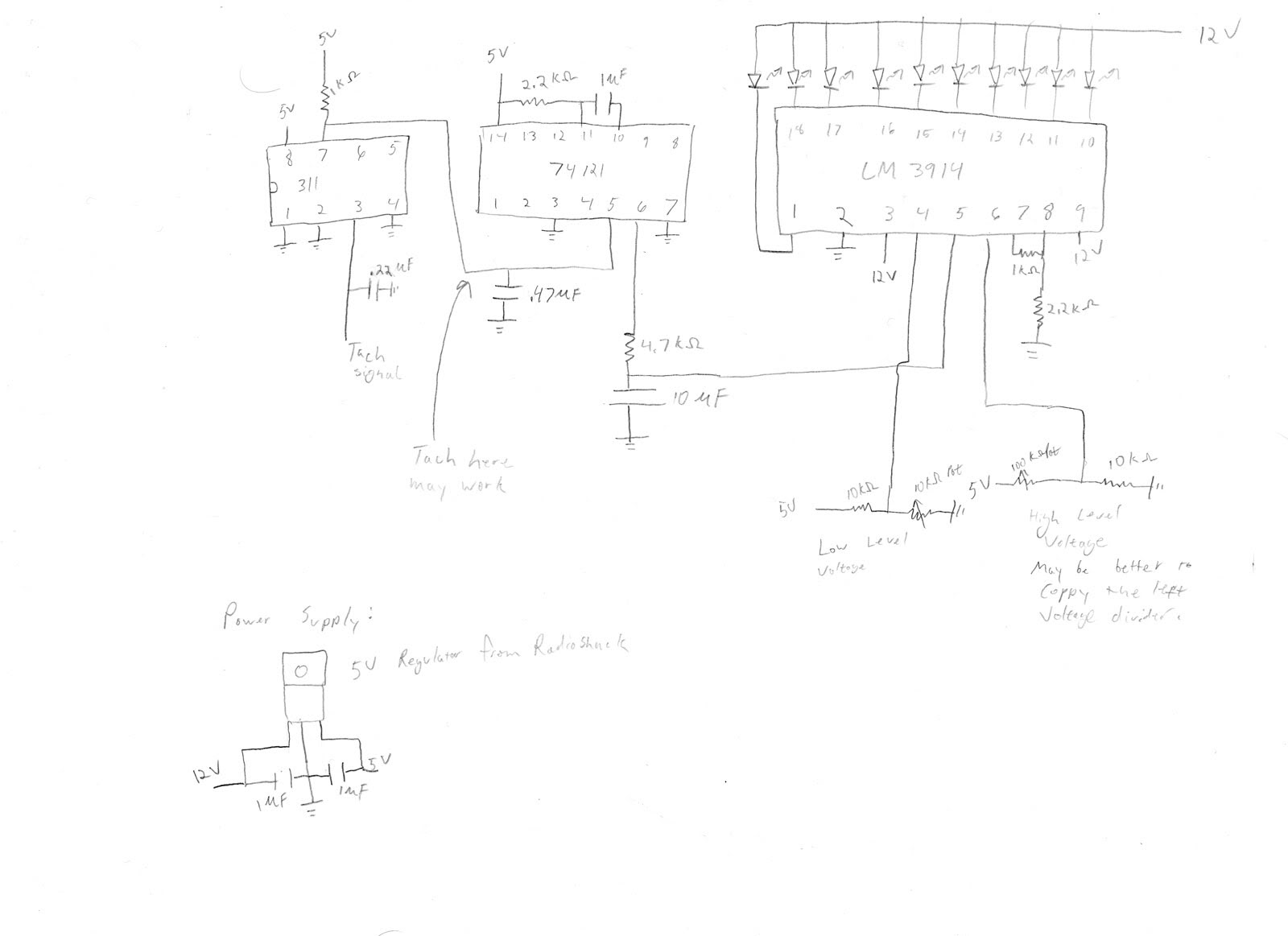
Sorry its a crappy drawing but oh well. First I'm a physicist not an electrical engineer so I only have a basic understanding of electronics. This circuit works but there may be things on it that are not optimal but gets the job done. Im not sure that the 311 chip is really needed. I didn't know if the 74121 could handle 12V as a trigger so i used a 311 to convert the tach signal to 5V. I have a note on the diagram where it may work to put the tach signal. Also if you use the 311 the .47 uF capacitor before the 74121 may not be needed either. I had noise issues and just put capacitors in random places until they went away. Pins 4 and 6 on the lm3914 are where the voltages that the leds light up are determined. Adjusting the pot on the voltage divider to pin 4 changes when the first led lights up. Looking at pin 6 no im not sure why i have different voltage dividers. In retrospect it would have been better to use the same setup as on pi 4 since the 100k pot i used is touchy and hard to dial in. This divider on pin 6 controls when the last led turns on. Using the two pots you can set when the leds come on. I set mine to start at 6000rpm and end at 7000. If you replace the 1k resistor between pins 7 and 8 with a pot you can change the brightness of the leds. With the 1k it's a little dimmer than i would likee during the day but bright at night. Putting a shade around the leds should fix it though.
Sorry its a crappy drawing but oh well. First I'm a physicist not an electrical engineer so I only have a basic understanding of electronics. This circuit works but there may be things on it that are not optimal but gets the job done. Im not sure that the 311 chip is really needed. I didn't know if the 74121 could handle 12V as a trigger so i used a 311 to convert the tach signal to 5V. I have a note on the diagram where it may work to put the tach signal. Also if you use the 311 the .47 uF capacitor before the 74121 may not be needed either. I had noise issues and just put capacitors in random places until they went away. Pins 4 and 6 on the lm3914 are where the voltages that the leds light up are determined. Adjusting the pot on the voltage divider to pin 4 changes when the first led lights up. Looking at pin 6 no im not sure why i have different voltage dividers. In retrospect it would have been better to use the same setup as on pi 4 since the 100k pot i used is touchy and hard to dial in. This divider on pin 6 controls when the last led turns on. Using the two pots you can set when the leds come on. I set mine to start at 6000rpm and end at 7000. If you replace the 1k resistor between pins 7 and 8 with a pot you can change the brightness of the leds. With the 1k it's a little dimmer than i would likee during the day but bright at night. Putting a shade around the leds should fix it though.
Reply
0
0
06-03-2009, 07:35 PM
#15
Elite Member
Thread Starter
iTrader: (7)
Join Date: Jan 2007
Location: Renton Washington
Posts: 1,731
Total Cats: 4
i absolutley love it 
Could you generate a parts list and maybe a place to buy them? I would like to get started soon. I would like to be able to program it to do 1000rpm-7000rpm with 10 LED's
Could you generate a parts list and maybe a place to buy them? I would like to get started soon. I would like to be able to program it to do 1000rpm-7000rpm with 10 LED's
Reply
0
0
06-03-2009, 08:58 PM
#16
Here are the parts
ICs:
lm311 Comparator
dm74121 Monostable Multivibrator
lm3914 LED Bar Graph Driver
Capacitors:
.22 uF (x1)
.47 uF (x1)
1 uF (x3)
10 uF (x1)
Make sure you get the polarity right on these or else they explode. The side that goes towards negative is usually marked.
Resistors:
1 kohm (x2)
2.2 kohm (x2)
4.7 kohm (x1)
10 kohm (x2)
10 kohm Potentiometer (x1)
100 kohm Potentiometer (x1)
5V Regulator 7805
10 LEDs of your choice
Project Box
Board
Wire
The box was the smallest one i saw at radioshack. The board used was something that was just laying around in lab so i suggest checking out radioshack and seeing what they have. I suggest buying extra components just in case.
Also a video of it working:
Last edited by cjsafski; 06-03-2009 at 09:01 PM. Reason: I fail at youtube links
Reply
0
0
02-09-2014, 03:46 PM
#17

Googling DIY LED Tachometer produced many hits. A couple of examples:
LED Tachanometer - How-to-Guides & Manuals, scheme, and Tricks (You can substitute a takeoff of one of the ignition trigger lines for the coil of wire.)
LED Bargraph Optical Tachometer (use a regular NPN in place of the PT501)
LED Tachanometer - How-to-Guides & Manuals, scheme, and Tricks (You can substitute a takeoff of one of the ignition trigger lines for the coil of wire.)
LED Bargraph Optical Tachometer (use a regular NPN in place of the PT501)
Reply
0
0

Thread
Thread Starter
Forum
Replies
Last Post
StratoBlue1109
Miata parts for sale/trade
21
09-30-2018 01:09 PM
Mikel
MEGAsquirt
29
09-14-2015 09:11 AM
shinobix
Miata parts for sale/trade
2
04-17-2007 08:53 PM


