STACK'd Miata Arduino-Controlled Gauge Cluster
 03-26-2015, 11:52 PM
#1
Junior Member
Thread Starter
iTrader: (9)

Join Date: Dec 2011
Location: SFBay
Posts: 408
Total Cats: 61
This has been my project over the past 4 months or so. I thought I should make a thread to document the project.
After the SweepOTron board, my previous project, I learned the basics of electronics design and layout.
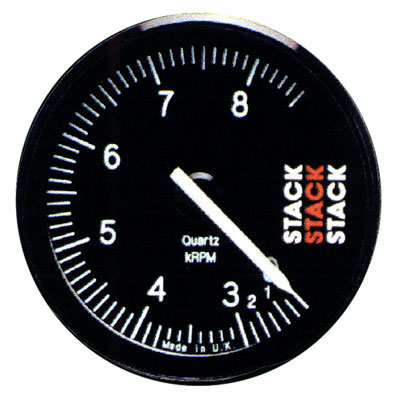
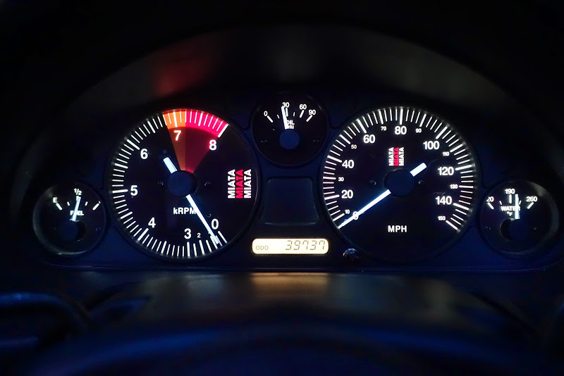
As I was designing that board, I was thinking about how cool it would be to emulate the non-linear compressed tachometer action of a STACK cluster for my track NB1:
After I got the SweepOTron board on my AWD cluster working and installed in my MSM, I decided to try and take on the project of making a custom cluster for the NB1.
I thought I would have to use some kind of microcontroller to make the scale non-linear. I thought I could use an Arduino, but had never used a programmable microcontroller like it before. I liked the small ones that Sparkfun sold, so I ordered a couple.
I also thought I could use the same gauge controller that I used on the SweepOTron by forcing a voltage from the microcontroller to manually point the needle where I wanted it, but it turned out there was an even better option. Theres another gauge controller that could be controlled via SPI serial connection, which it turns out the Arduino supports natively.
I ordered a bunch of parts and hacked it all together until I could control the gauge from the Arduino. This was a huge coup for me, since this was uncharted territory.
I also got lucky and found that the FreqMeasure library would do exactly what I needed in terms of reading in the RPM of the engine. The RPM was fed in from the tach at 12V, but the Arduino only ran at 5V, so I used a way-overkill optocoupler circuit to drive the RPM input.
At this point, I was feeling confident enough that this would work to have Adam @ revlimiter.net make me a custom set of gauges with a compressed tachometer.
We designed some gauge faces that were a true homage to the STACK gauges
We went back and forth and finally settled on a design down to the fonts and thickness and length of the tick marks.
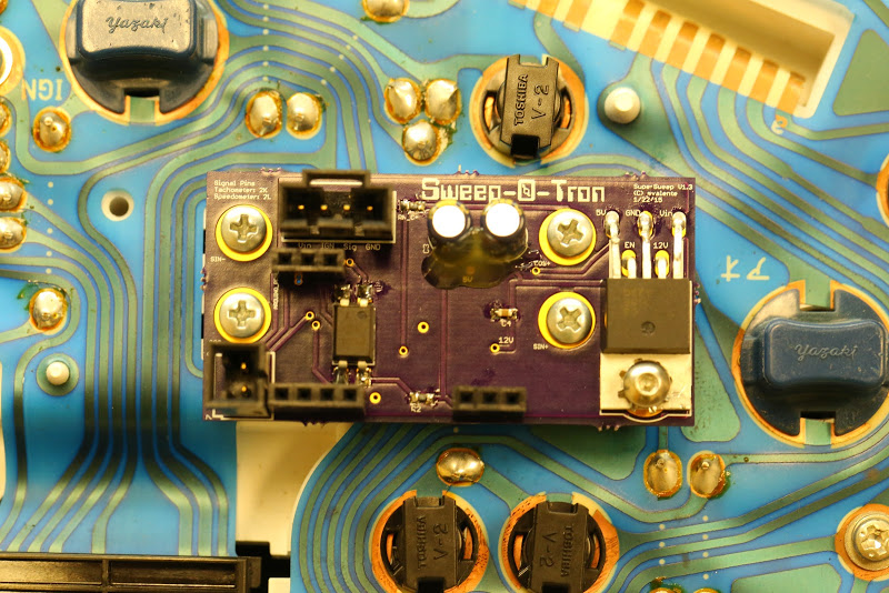
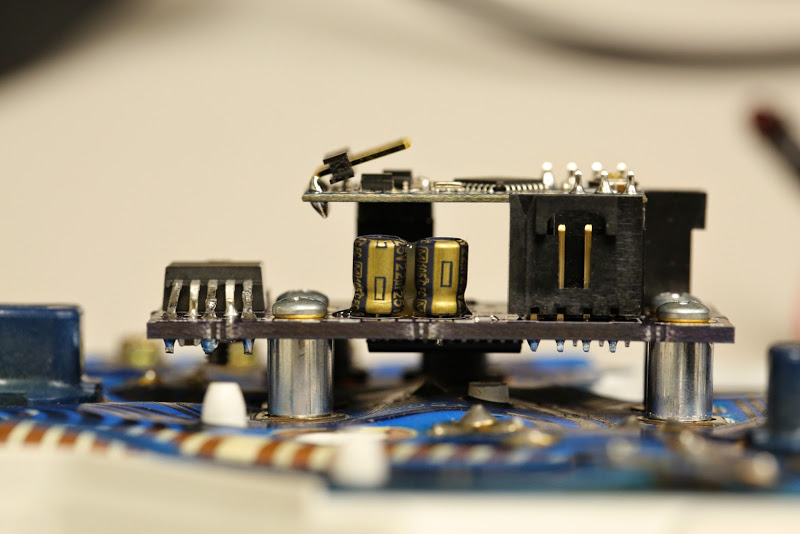
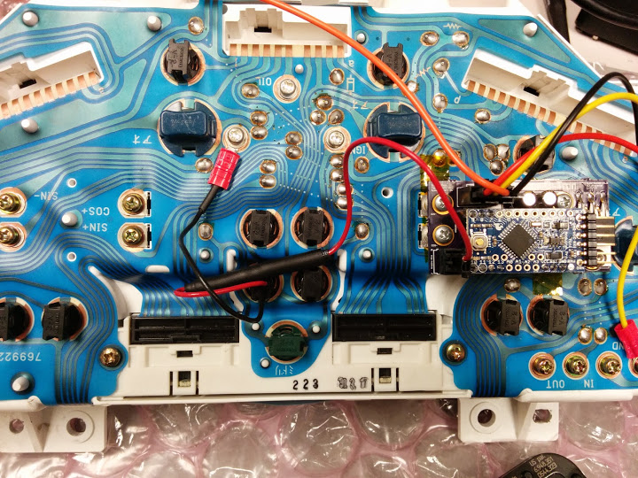
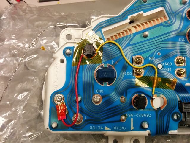
In the meantime, I started the layout of the actual board. I decided it was above my abilities to put the Arduino directly onto a custom board, so I designed the board to socket the Sparkfun Arduino onto a simpler board. The board, which I called SuperSweep, had an automotive 5V/12V regulator, some power stabilization caps, and the gauge controller and optocoupler. I also ran two of the general I/O pins to a separate header in case I thought of something in the future.
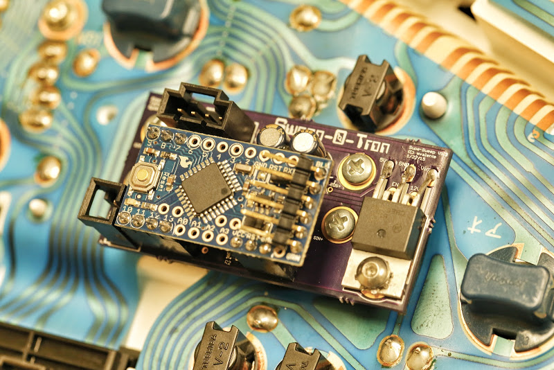
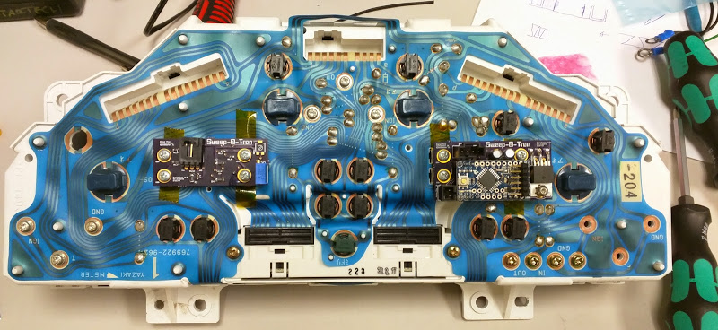
With the Arduino board installed
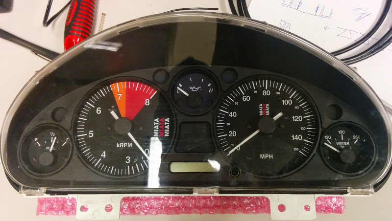
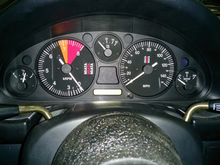
Old busted on left, new hotness on right
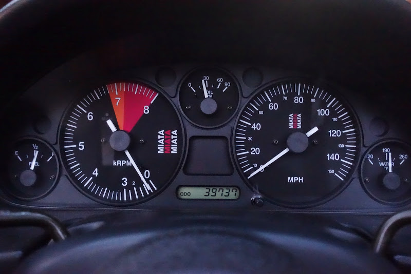
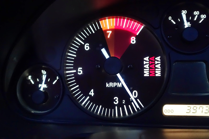
When the new faces arrived, I was incredibly pleased. The oil pressure gauge isn't installed in this picture because I'm using an NA gauge and sender and had to modify the housing to fit.
I had to tweak the scale and offset in the Arduino code to get it right, but it ended up working out extremely well
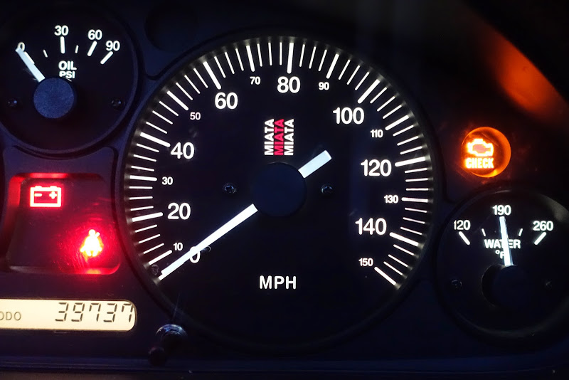
I also decided that since I already had the RPM input on the Arduino, I should make use of it and impement a shift light.
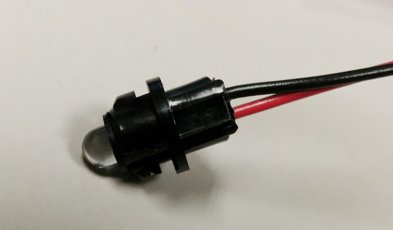
I found a super-bright LED that fit into a drilled-out bulb holder, and replaced the seatbelt light. I used the 6101 LED for the red shift light. I needed to solder a current limiting resistor in series, but the LED was much brighter than the incandescent bulbs.
I wrote some code so it would be steady above a certain RPM and flash at a higher RPM. I was absolutely shocked when it worked the first time.
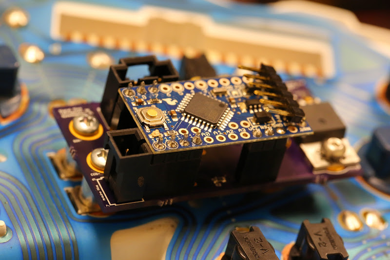
I eventually discovered that the whole board was too deep so I couldnt mount the cluster flush, so I had to replace the connector sockets with right angle versions and replace the standoffs with slightly shorter versions to reduce the height.
Finally today I got it all put back together.
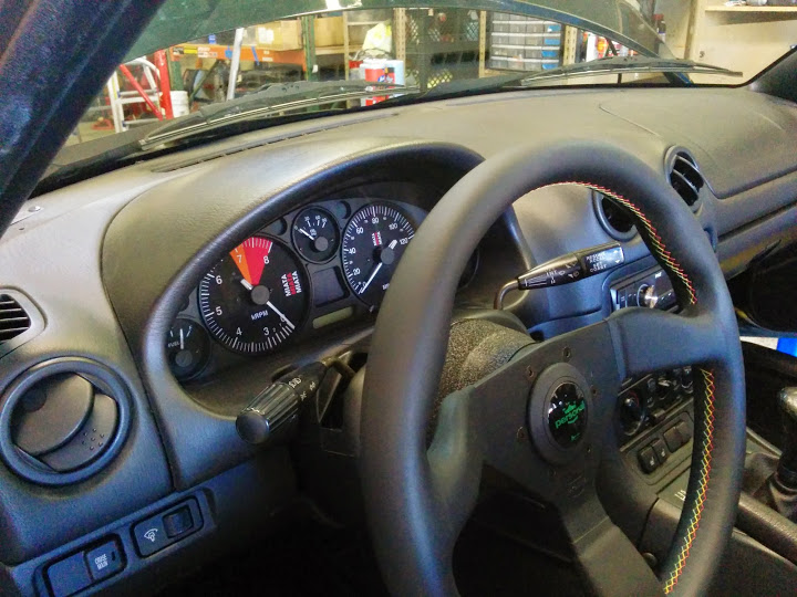
With wiring harness and CEL relocated

The cluster does a simple staging sweep on startup
And the shift light works great, though it's hard to show while revving in neutral.
After the SweepOTron board, my previous project, I learned the basics of electronics design and layout.
As I was designing that board, I was thinking about how cool it would be to emulate the non-linear compressed tachometer action of a STACK cluster for my track NB1:
After I got the SweepOTron board on my AWD cluster working and installed in my MSM, I decided to try and take on the project of making a custom cluster for the NB1.
I thought I would have to use some kind of microcontroller to make the scale non-linear. I thought I could use an Arduino, but had never used a programmable microcontroller like it before. I liked the small ones that Sparkfun sold, so I ordered a couple.
I also thought I could use the same gauge controller that I used on the SweepOTron by forcing a voltage from the microcontroller to manually point the needle where I wanted it, but it turned out there was an even better option. Theres another gauge controller that could be controlled via SPI serial connection, which it turns out the Arduino supports natively.
I ordered a bunch of parts and hacked it all together until I could control the gauge from the Arduino. This was a huge coup for me, since this was uncharted territory.
I also got lucky and found that the FreqMeasure library would do exactly what I needed in terms of reading in the RPM of the engine. The RPM was fed in from the tach at 12V, but the Arduino only ran at 5V, so I used a way-overkill optocoupler circuit to drive the RPM input.
At this point, I was feeling confident enough that this would work to have Adam @ revlimiter.net make me a custom set of gauges with a compressed tachometer.
We designed some gauge faces that were a true homage to the STACK gauges
We went back and forth and finally settled on a design down to the fonts and thickness and length of the tick marks.
In the meantime, I started the layout of the actual board. I decided it was above my abilities to put the Arduino directly onto a custom board, so I designed the board to socket the Sparkfun Arduino onto a simpler board. The board, which I called SuperSweep, had an automotive 5V/12V regulator, some power stabilization caps, and the gauge controller and optocoupler. I also ran two of the general I/O pins to a separate header in case I thought of something in the future.
With the Arduino board installed
Old busted on left, new hotness on right
When the new faces arrived, I was incredibly pleased. The oil pressure gauge isn't installed in this picture because I'm using an NA gauge and sender and had to modify the housing to fit.
I had to tweak the scale and offset in the Arduino code to get it right, but it ended up working out extremely well
I also decided that since I already had the RPM input on the Arduino, I should make use of it and impement a shift light.
I found a super-bright LED that fit into a drilled-out bulb holder, and replaced the seatbelt light. I used the 6101 LED for the red shift light. I needed to solder a current limiting resistor in series, but the LED was much brighter than the incandescent bulbs.
I wrote some code so it would be steady above a certain RPM and flash at a higher RPM. I was absolutely shocked when it worked the first time.
I eventually discovered that the whole board was too deep so I couldnt mount the cluster flush, so I had to replace the connector sockets with right angle versions and replace the standoffs with slightly shorter versions to reduce the height.
Finally today I got it all put back together.
With wiring harness and CEL relocated
The cluster does a simple staging sweep on startup
And the shift light works great, though it's hard to show while revving in neutral.
Last edited by scenturion; 03-27-2015 at 01:54 AM.

Reply
 6
6

6


 03-27-2015, 12:34 AM
#5
Junior Member
Thread Starter
iTrader: (9)
Join Date: Dec 2011
Location: SFBay
Posts: 408
Total Cats: 61
I did run into some strange issues with the CS4122 and the SPI library where the device wanted LSB first, but it only worked if I set the SPI mode to MSB first

Reply
0
0
 03-27-2015, 12:56 AM
#7
Junior Member
Thread Starter
iTrader: (9)
Join Date: Dec 2011
Location: SFBay
Posts: 408
Total Cats: 61
Also: funny story. When I put it all together today I found that the car wouldn't turn off. I turned the key off and removed it, but the car kept running. I had to remove the cluster to stop the car.
Turns out, the CEL relocation wire from IGN wore through the tape underneath the light, connecting IGN and +. Effectively, I hotwired my own car

Last edited by scenturion; 03-27-2015 at 01:24 AM.
Reply
0
0
03-27-2015, 01:53 AM
#9
Junior Member
Thread Starter
iTrader: (9)
Join Date: Dec 2011
Location: SFBay
Posts: 408
Total Cats: 61
Nah, it's a pretty complicated part and not really meant for public consumption. You have to be willing to get custom gauge faces and then be competent enough in programming to modify my Arduino code to work with your gauge face design.
I have a single spare if anyone is hugely interested, but it's definitely not for the average Miata enthusiast.
I have a single spare if anyone is hugely interested, but it's definitely not for the average Miata enthusiast.
Reply
0
0


 mind sharing your 12to5v conversion parts/schematics?
03-28-2015, 06:51 PM
mind sharing your 12to5v conversion parts/schematics?
03-28-2015, 06:51 PM
#13
Junior Member
Thread Starter
iTrader: (9)
Join Date: Dec 2011
Location: SFBay
Posts: 408
Total Cats: 61
Anyone want one?
For the power supply circuit, I used the now-discontinued CS8156.
It's perfect for what I needed - dual 12V and 5V regulation and qualified for automotive use.
Rochester Electronics has these parts on closeout but has a min-spend of like $50.
I bought a dozen of them as I intend to use them in all future potential automotive electronics projects. I can probably spare one if that's all you need.
The schematic is simple, I mostly followed the reference design. I put a .1uF ceramic bypass on Vin, and put separate 22uF 25V electrolytics on the 5V and 12V lines. According to everything I read (or tried to read), matching the impedance of the stabilization caps to the rest of the downstream circuit is supposed to be important, but the process for getting it right required more patience and effort than I had, so I ignored it. In addition, the Pro Mini has its own built in stabilization cap, so the effective capacitance on the 5V line is higher (and impedance is lower I guess), but it doesn't seem to matter in the least.
I also put a 20k resistor on ENA to make sure it didnt sink too much current.
Originally I had ENA connected to IGN and Vin connected to +, but it resulted in some weird behavior I couldn't diagnose where the Arduino wouldnt always reset properly. I ended up connecting both to IGN and it works fine now.
I'd be happy to send you the actual schematic but I need to clean it up a bit first.
Reply
0
0
03-28-2015, 06:57 PM
#14
SADFab Destructive Testing Engineer


iTrader: (5)
Join Date: Apr 2014
Location: Beaverton, USA
Posts: 18,642
Total Cats: 1,866
12v to 5v is really simple. Radio shack sells a 5v regulator that will take 5-35v.
Any chance of posting your schematics and board design files? I am interested in this for a future project.
Any chance of posting your schematics and board design files? I am interested in this for a future project.
Reply
0
0
03-28-2015, 08:30 PM
#15
Junior Member
Thread Starter
iTrader: (9)
Join Date: Dec 2011
Location: SFBay
Posts: 408
Total Cats: 61
Try out the ONSemi LDO recommendation tool here or look through and sort all of the options here.
To be honest, the schematic and board design are pretty simple; Theres only about a dozen parts including standoffs and connectors. The far trickier part is the Arduino code, which took much longer to get right than the schematic and board layout. I did a decent job of documenting that code, so it would be easier to post.
Reply
0
0
03-28-2015, 08:33 PM
#16
SADFab Destructive Testing Engineer
iTrader: (5)
Join Date: Apr 2014
Location: Beaverton, USA
Posts: 18,642
Total Cats: 1,866
There are some good open source sites around. I'm most interested in the board files so I don't have to mess around with the cad design. The schematic and the code is the easy part for me.
Reply
0
0


Thread
Thread Starter
Forum
Replies
Last Post


