120VAC wiring help
 09-29-2009, 10:02 PM
#1
Elite Member
Thread Starter
iTrader: (3)
Join Date: Oct 2004
Location: lansdale PA
Posts: 2,494
Total Cats: 0
i got a new bath fan, here's how they want it installed:
http://www.broan.com/ImageLibrary/br...s/99044368.pdf
can i do it this way?
i want the fan to come on with the light switch, but i also want the humidity sensing switch to operate indepedently, can i do this?
http://www.broan.com/ImageLibrary/br...s/99044368.pdf
can i do it this way?
i want the fan to come on with the light switch, but i also want the humidity sensing switch to operate indepedently, can i do this?

Reply
 0
0

0
 09-30-2009, 12:35 AM
#3
Elite Member
Thread Starter
iTrader: (3)
Join Date: Oct 2004
Location: lansdale PA
Posts: 2,494
Total Cats: 0
black is hot in ac, trouble is a house doesn't work like a car so i have to unlearn stuff
both circuits have a hot, one leading to the switched on the other giving constant power for the humidity sensor, at least that's how it's working in my mind. will it be a problem if the switch is on and the humidity sensor is tripped at the same time?
both circuits have a hot, one leading to the switched on the other giving constant power for the humidity sensor, at least that's how it's working in my mind. will it be a problem if the switch is on and the humidity sensor is tripped at the same time?
Reply
0
0
09-30-2009, 12:38 AM
#4
nah it works like a car except you have the black is hot and the cold wich is whatever collor you have and the ground with until like the mid 90's was a flybynight option. And realy came into play when flourescent bulbs etc are put into play. But the electricity is still the same hot a cold with a ground for safety as it where to disipate any roque energy. And instead of grounding to your frame or block etc your negative needs to go back to the box this means that the picture you show lacks a negative lead going into the system and will not work.
Unless the new circiut is fresh wire etc you pulled to the box and the hot feed off the light switch goes into a relay to engage the internal mechanism of the fan.
Unless the new circiut is fresh wire etc you pulled to the box and the hot feed off the light switch goes into a relay to engage the internal mechanism of the fan.
Reply
0
0
09-30-2009, 09:06 AM
#5
Boost Pope


iTrader: (8)
Join Date: Sep 2005
Location: Chicago. (The less-murder part.)
Posts: 33,026
Total Cats: 6,592
We'll all be killed...
For residential work in the US, the following standards apply:
White is always neutral.
Black is always hot. In a three-phase (208/230) environment, red and blue are also hot. (480/277 3-phase circuits use a brown-yellow-orange scheme)
In single-phase 110/220 applications where both hot legs are present in a circuit, one is always black, the other is almost always red. In such an environment, the potential between white and black or white and red is 110v, the potential between black & red is 220v.
In single-phase applications where two or more unique hot wires are present in a circuit (such as on a three-way switch or a multi-gang switch) they are typically coded 1-black, 2-red, 3-blue, 4-yellow... It is both permissible and not uncommon for other colors to be used for additional hot legs, so long as they are not white or green.
For a 220v appliance where no neutral is needed, standard white/black/gnd romex is often used, with the white wire carrying the second hot leg in lieu of a red wire. The white wire must be clearly marked at both ends to indicate this use, usually with a few turns on black or red electrical tape.
Ground may be uninsulated when in romex or NMT, but must be jacketed in green or green/yellow if in a metallic carrier.
black and red.
(Note that this refers only to premise wiring.)
Now, check out Wiring Option #2 in the documentation:

The "Model 68W" switch they refer to is a non-interlocking two circuit switch. Here's the documentation on it: http://www.plumbersurplus.com/pdf/99043739.pdf
So, wiring it the way you propose is essentially the same as if you wired it as per Option #2 and simply left the lower switch "on" all the time.
For residential work in the US, the following standards apply:
White is always neutral.
Black is always hot. In a three-phase (208/230) environment, red and blue are also hot. (480/277 3-phase circuits use a brown-yellow-orange scheme)
In single-phase 110/220 applications where both hot legs are present in a circuit, one is always black, the other is almost always red. In such an environment, the potential between white and black or white and red is 110v, the potential between black & red is 220v.
In single-phase applications where two or more unique hot wires are present in a circuit (such as on a three-way switch or a multi-gang switch) they are typically coded 1-black, 2-red, 3-blue, 4-yellow... It is both permissible and not uncommon for other colors to be used for additional hot legs, so long as they are not white or green.
For a 220v appliance where no neutral is needed, standard white/black/gnd romex is often used, with the white wire carrying the second hot leg in lieu of a red wire. The white wire must be clearly marked at both ends to indicate this use, usually with a few turns on black or red electrical tape.
Ground may be uninsulated when in romex or NMT, but must be jacketed in green or green/yellow if in a metallic carrier.
black and red.
(Note that this refers only to premise wiring.)
Now, check out Wiring Option #2 in the documentation:
The "Model 68W" switch they refer to is a non-interlocking two circuit switch. Here's the documentation on it: http://www.plumbersurplus.com/pdf/99043739.pdf
So, wiring it the way you propose is essentially the same as if you wired it as per Option #2 and simply left the lower switch "on" all the time.
Reply
0
0
09-30-2009, 09:16 AM
#6
Boost Czar

iTrader: (62)
Join Date: May 2005
Location: Chantilly, VA
Posts: 79,493
Total Cats: 4,080
Yep just need that switch. So the Common (white) and GRD (copper) get wired directly to the unit, the 110v (black) goes into the switch then out to the BRN and ORG on the unit. It's essentially the same wiring as #1 but you spitting the power at the switch and giving the unit it's magical constant power.
Reply
0
0
09-30-2009, 09:21 AM
#8
Elite Member
Thread Starter
iTrader: (3)
Join Date: Oct 2004
Location: lansdale PA
Posts: 2,494
Total Cats: 0

anyhow, i'm a little confused. What do you mean by the lower switch on all the time?
are you saying that the way i have it drawn up will only activate with the lower switch on?
what i really want is that the fan will come on when the switch is on, because if someone takes a nasty **** i want it to expel the stench. I also want the humidity sensor portion of the fan to be able to operate the fan when the light switch is turned off, because i like to get a shower in the morning with the light off. Also with this fan, when the humidity sensor activates the fan it will stay running for an additional 20 minutes to make sure it gets rid of most of the moisture. that way i can leave the bathroom, get dressed and leave for work without leaving the bathroom light on all day.
Reply
0
0
09-30-2009, 09:23 AM
#10
Boost Czar
iTrader: (62)
Join Date: May 2005
Location: Chantilly, VA
Posts: 79,493
Total Cats: 4,080
look at my post again, I included a picture of the switch.
basically the power is going into the switch and splitting. The ORG should always be powered for the auto function, and the top will manually control the fan when you want it.
Reply
0
0
09-30-2009, 09:31 AM
#12
Boost Pope
iTrader: (8)
Join Date: Sep 2005
Location: Chicago. (The less-murder part.)
Posts: 33,026
Total Cats: 6,592
Love. 
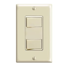
In the diagram provided with the fan, in "Option #2" they depict a model 68W switch. I provided a link to the documentation for that switch, and Brainey posted a picture of it.
The 68W is just two switches in one housing, an upper and a lower, which share a common input and have two separate outputs.
In "Option #2", the upper switch is connected to the orange wire at the fan, and thus controls the manual on/off function. The lower switch is connected to the brown wire at the fan, and controls the automatic function.
In looking at what I just wrote, I realize I mis-typed, and I believe your diagram may be backwards. It looks like you want to tie the brown wire directly to the incoming hot leg, and put the switch on the orange wire. This should be equivalent to leaving the lower switch turned on all the time in "Option #2".
anyhow, i'm a little confused. What do you mean by the lower switch on all the time?
The 68W is just two switches in one housing, an upper and a lower, which share a common input and have two separate outputs.
In "Option #2", the upper switch is connected to the orange wire at the fan, and thus controls the manual on/off function. The lower switch is connected to the brown wire at the fan, and controls the automatic function.
In looking at what I just wrote, I realize I mis-typed, and I believe your diagram may be backwards. It looks like you want to tie the brown wire directly to the incoming hot leg, and put the switch on the orange wire. This should be equivalent to leaving the lower switch turned on all the time in "Option #2".
Reply
0
0
09-30-2009, 09:37 AM
#13
Supporting Vendor

iTrader: (33)
Join Date: Jul 2006
Location: atlanta-ish
Posts: 12,659
Total Cats: 134
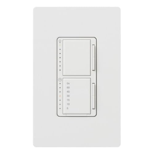
I've also seen a decora style single gang dual switch that was a combination light dimmer and fan timer at home depot. Kinda pricey, but I like dimmers.
<edit>
Or you can replace your existing switch/outlet combo with a dual switch combo, and then towards the center of the stud bay simply install a GFI in a retro box. No sheetrock work required that way.

Reply
0
0
09-30-2009, 09:39 AM
#14
Elite Member
Thread Starter
iTrader: (3)
Join Date: Oct 2004
Location: lansdale PA
Posts: 2,494
Total Cats: 0
****, i feel like an idiot over here. getting more confused
you guys are suggesting new switches. can this be done with my existing normal, single on/off switch?
you guys are suggesting new switches. can this be done with my existing normal, single on/off switch?
Reply
0
0
09-30-2009, 09:51 AM
#16
Supporting Vendor
iTrader: (33)
Join Date: Jul 2006
Location: atlanta-ish
Posts: 12,659
Total Cats: 134
Replace your existing single gang combination switch/outlet with this combination light dimmer/fan timer
Then a few inches from the switch location, install a retro box with a GFI outlet. You will have to run a small lead of romex from the swtich location to the outlet location.

You can also put the switch and outlet side by side in a double gang box, but it will require a little sheetrock finishing work.
Reply
0
0
09-30-2009, 09:59 AM
#17
Boost Pope
iTrader: (8)
Join Date: Sep 2005
Location: Chicago. (The less-murder part.)
Posts: 33,026
Total Cats: 6,592
From what I gather in all this, the big holdup is needing to work with an existing wire in the wall which is currently supplying an incandescent fixture, and not wanting to run additional wiring from the j-box up to the fixture. I can sympathize with this. Assuming that an unswitched hot wire is available in the location where you want to put the fan, all is well.
Reply
0
0
09-30-2009, 10:28 AM
#18
Elite Member
Thread Starter
iTrader: (3)
Join Date: Oct 2004
Location: lansdale PA
Posts: 2,494
Total Cats: 0
thanks scott, do you also agree with switching brown and orange? either way it's an easy switch back and i can't really see any harm.
Ben i'll trying to keep costs and work to a minumum, since it's also a little daunting for me to also have to cut a hole in my roof.
exactly joe, i have a new junction box i installed when i put ceiling fans in, it's directly over where i'll be putting the fan.
anyway you guys are the best!
and joe i'll make you an expert on love, are you allergic to latex?
Reply
0
0
09-30-2009, 10:38 AM
#19
Boost Czar
iTrader: (62)
Join Date: May 2005
Location: Chantilly, VA
Posts: 79,493
Total Cats: 4,080
yeah, the constant black wire should go the BRN and the switched black wire to ORG.
Look at Option #2 in the pdf, when power goes to the BRN wire, it's using the Humidity Controls, the red to orange is labeled as fan on/off.
Look at Option #2 in the pdf, when power goes to the BRN wire, it's using the Humidity Controls, the red to orange is labeled as fan on/off.
Reply
0
0
09-30-2009, 10:39 AM
#20
Supporting Vendor
iTrader: (33)
Join Date: Jul 2006
Location: atlanta-ish
Posts: 12,659
Total Cats: 134
Dude if you get a standard type single gang combo switch, single gang retro box, and a GFI outlet (you'll already have romex), you'll spend about $20. The most expensive part by far is the GFI outlet. You'll then at any time be able to run dimmers or timers. I don't understand how people don't have dimmers on bathroom lights personally.
Upside:
You have independent fan and light control so the bathroom does not feel like a motel, plus your power outlet will be GFI protected.
Reply
0
0


