The AI-generated cat pictures thread
 10-28-2015, 10:17 AM
Senior Member

Join Date: Aug 2008
Location: Maryville TN
Posts: 878
Total Cats: 79
We had one of those old tables at my precious job that was converted to a big x-y scanner. it was pretty neat.

Reply
 0
0

0
10-28-2015, 10:38 AM
Boost Pope


iTrader: (8)
Join Date: Sep 2005
Location: Chicago. (The less-murder part.)
Posts: 33,023
Total Cats: 6,591
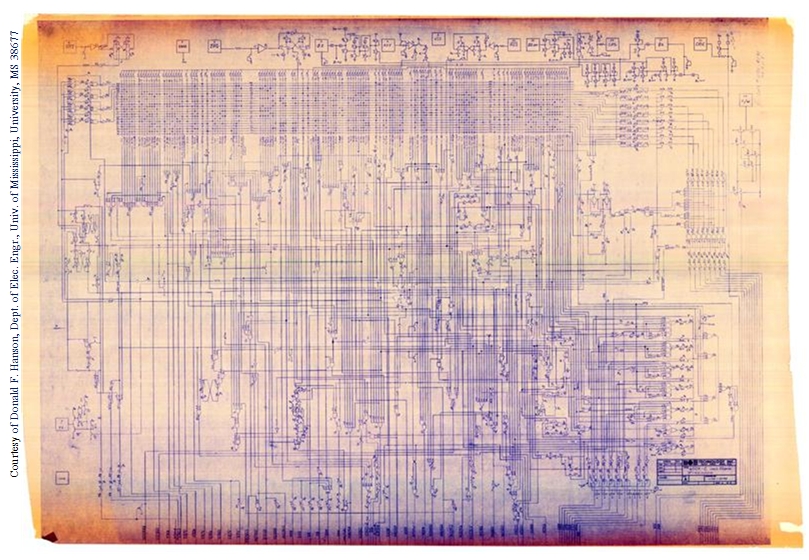
They started by drawing a conventional schematic diagram of the CPU, as if it were a PCB. This was familiar technology, as in the pre-microprocessor era, A CPU WAS a printed circuit board (sometimes several of them) loaded with discrete components and maybe some simple IC logic chips.
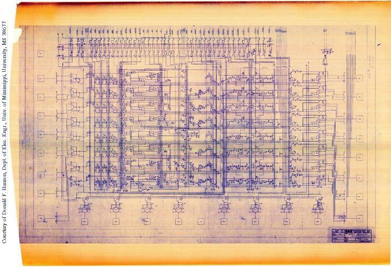
Then, they re-draw the schematic in a form which loosely mirrors what will become the physical layout of the die, still using component symbols, but with all interconnect lines drawn as though they were physical bus wires, and no pointers.
Here's the layout schematic for the 6502:
Then, a small cadre of people (nicknamed sandbenders) who know how to physically form active components out of silicon translate the layout-schematic into a set of onionskin drawings which convert the schematic symbols into physical shapes. They do one layer of paper for each mask layer.
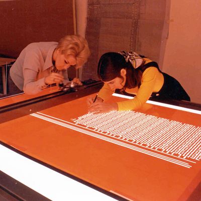
Finally, the layout drawing is re-created using plastic sheets on a light table, which is the step depicted above. Once complete, each layer is photographed with a camera, and then the developed film is used to etch the lithography masks which will be used in fabrication.
Yup.
The first transitional step was that software translated schematics into layout.
The next step was object-oriented schematics (like what's sometimes used to create FPGA designs), where rather than having to draw every single FET and capacitor, the designer just grabs a block which represents some common thing (like a register or an arithmetic unit) and drops it into a design which is sort of a hybrid between a schematic and a block diagram.
These days, the designers don't even look at schematics. They describe the desired functionality of the device in something like VHDL or Verilog which is then run through several layers of software to produce a layout.
Cool stuff, though I can't help but suspect that EDA-generated layouts posses the same sort of sub-optimality as software written in a high-level language and then run through a compiler as compared to code generated in assembly.
When I worked at Harris, we still had all of our old lithos for PCB manufacturing dating back to the 70s, though we didn't start designing our own ASICs until well into the CAD era. Every once in a blue moon, someone would call up needing a replacement circuit board for some obscure product that hadn't been made in a 30 years, and provided that they were willing to pay for it, we had the capacity to manufacture it. In the later years, I stopped sending the lithos out for fab and just started scanning them in the blueprint scanner, cleaning up and registering the artwork electronically, converting it to vectors, and fabbing from that.
Then, they re-draw the schematic in a form which loosely mirrors what will become the physical layout of the die, still using component symbols, but with all interconnect lines drawn as though they were physical bus wires, and no pointers.
Here's the layout schematic for the 6502:
Then, a small cadre of people (nicknamed sandbenders) who know how to physically form active components out of silicon translate the layout-schematic into a set of onionskin drawings which convert the schematic symbols into physical shapes. They do one layer of paper for each mask layer.
Finally, the layout drawing is re-created using plastic sheets on a light table, which is the step depicted above. Once complete, each layer is photographed with a camera, and then the developed film is used to etch the lithography masks which will be used in fabrication.
Yup.
The first transitional step was that software translated schematics into layout.
The next step was object-oriented schematics (like what's sometimes used to create FPGA designs), where rather than having to draw every single FET and capacitor, the designer just grabs a block which represents some common thing (like a register or an arithmetic unit) and drops it into a design which is sort of a hybrid between a schematic and a block diagram.
These days, the designers don't even look at schematics. They describe the desired functionality of the device in something like VHDL or Verilog which is then run through several layers of software to produce a layout.
Cool stuff, though I can't help but suspect that EDA-generated layouts posses the same sort of sub-optimality as software written in a high-level language and then run through a compiler as compared to code generated in assembly.
When I worked at Harris, we still had all of our old lithos for PCB manufacturing dating back to the 70s, though we didn't start designing our own ASICs until well into the CAD era. Every once in a blue moon, someone would call up needing a replacement circuit board for some obscure product that hadn't been made in a 30 years, and provided that they were willing to pay for it, we had the capacity to manufacture it. In the later years, I stopped sending the lithos out for fab and just started scanning them in the blueprint scanner, cleaning up and registering the artwork electronically, converting it to vectors, and fabbing from that.
Reply
0
0
10-28-2015, 12:12 PM
SADFab Destructive Testing Engineer

iTrader: (5)
Join Date: Apr 2014
Location: Beaverton, USA
Posts: 18,642
Total Cats: 1,866
Designs are still optimized after VHDL. Software can only do so good. It gets you 99% of the way but to have the best design possible you need to review all of it.
You can also run into issues where software places things in the wrong areas, which can lead to timing discrepancies. Say you have 3 blocks, all triggered by the same signal. 2 are right next to each other on one corner of the FPGA/ASIC, and the third is waaaayyyy over on the other corner. Signal propagation can end up being different and throwing you off.
You can also run into issues where software places things in the wrong areas, which can lead to timing discrepancies. Say you have 3 blocks, all triggered by the same signal. 2 are right next to each other on one corner of the FPGA/ASIC, and the third is waaaayyyy over on the other corner. Signal propagation can end up being different and throwing you off.
Last edited by aidandj; 10-28-2015 at 12:43 PM.
Reply
0
0
10-28-2015, 12:34 PM
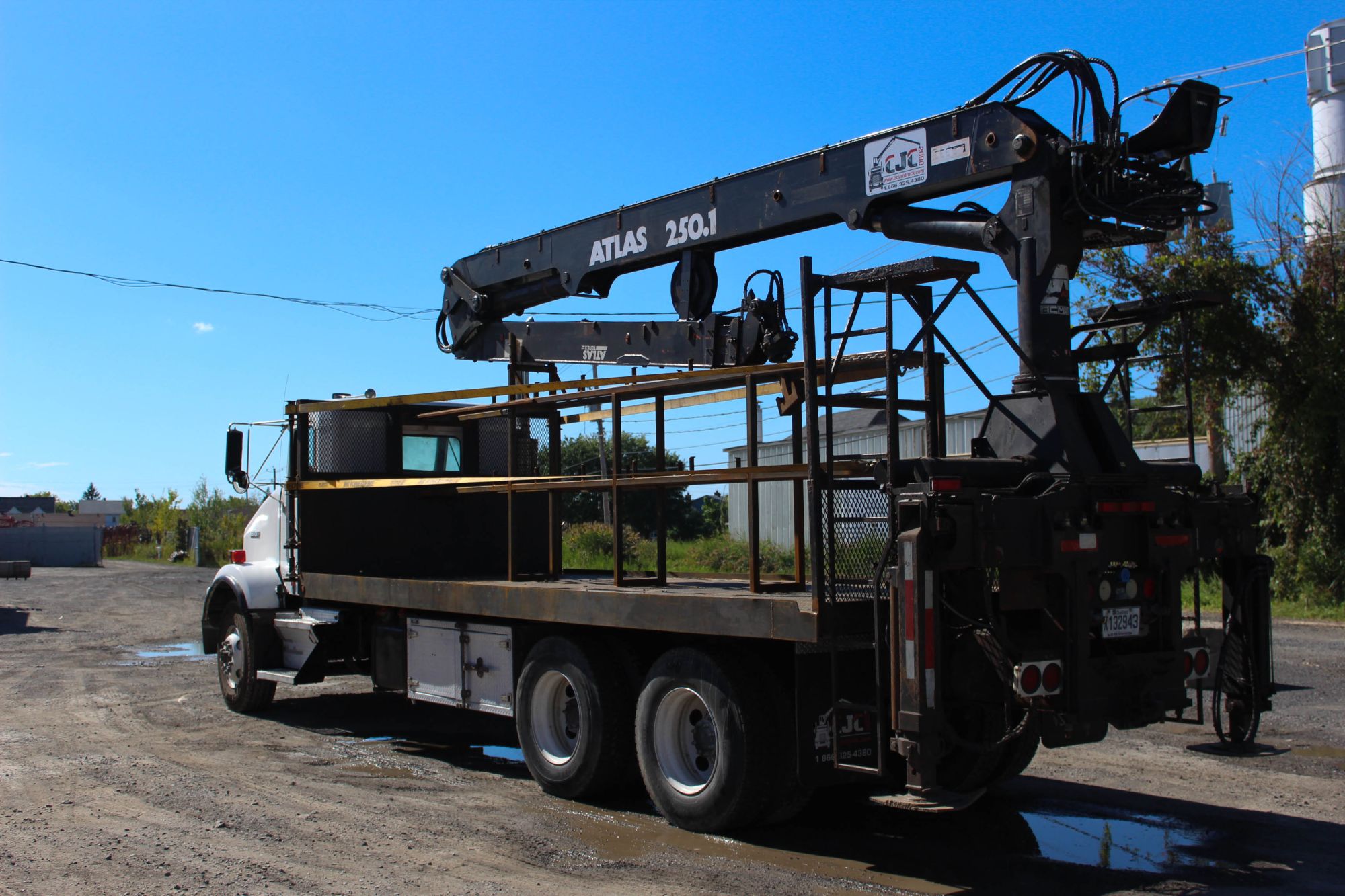
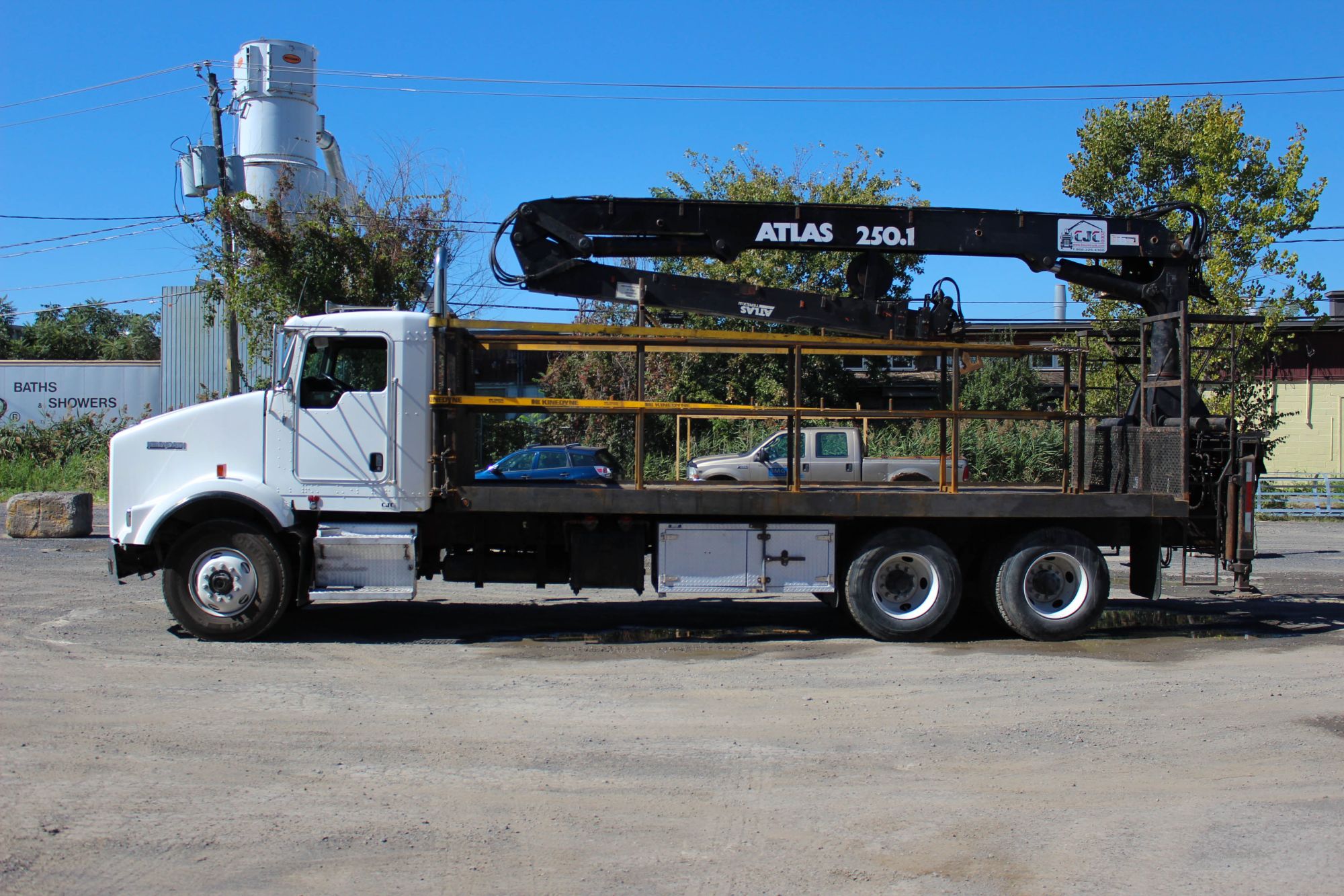
In the last 3 weeks I hired 4 new guys and just sent the wire transfer for our "new to us" boomtruck. A 2003 Kenworth T800, ready to go. I just have to get it over to our sign guy and have the logos put on.
It took a few years, but it feels great to finally have things turn out so well. Hoping to keep it going like this for another 50 years to come!

It took a few years, but it feels great to finally have things turn out so well. Hoping to keep it going like this for another 50 years to come!
Reply
0
0
10-28-2015, 12:46 PM
Boost Pope
iTrader: (8)
Join Date: Sep 2005
Location: Chicago. (The less-murder part.)
Posts: 33,023
Total Cats: 6,591
Designs are still optimized after FPGA. Software can only do so good. It gets you 99% of the way but to have the best design possible you need to review all of it.
You can also run into issues where software places things in the wrong areas, which can lead to timing discrepancies. Say you have 3 blocks, all triggered by the same signal. 2 are right next to each other on one corner of the FPGA/ASIC, and the third is waaaayyyy over on the other corner. Signal propagation can end up being different and throwing you off.
You can also run into issues where software places things in the wrong areas, which can lead to timing discrepancies. Say you have 3 blocks, all triggered by the same signal. 2 are right next to each other on one corner of the FPGA/ASIC, and the third is waaaayyyy over on the other corner. Signal propagation can end up being different and throwing you off.
IOW, with a PCB, you're starting with symbols, whereas with a modern CPU / GPU, you're starting with VHDL.
Interestingly, back at PR&E we had two guys were FPGA gurus. Started out with Actel, and later migrated to Xilinx. To the end, they did everything in schematic mode. VHDL was never used, and for largely the reasons you note. Our designs (audio DSP) were really pushing the bleeding edge of what was possible with gate-arrays at the time, and as such, the designs were amazingly well-optimized. Every single cell was hand-placed on the fabric. It was so cool to open up the design on your screen, and start zooming and zooming until you're looking at individual memory blocks.
A far cry from the days when a CPU looked like this:
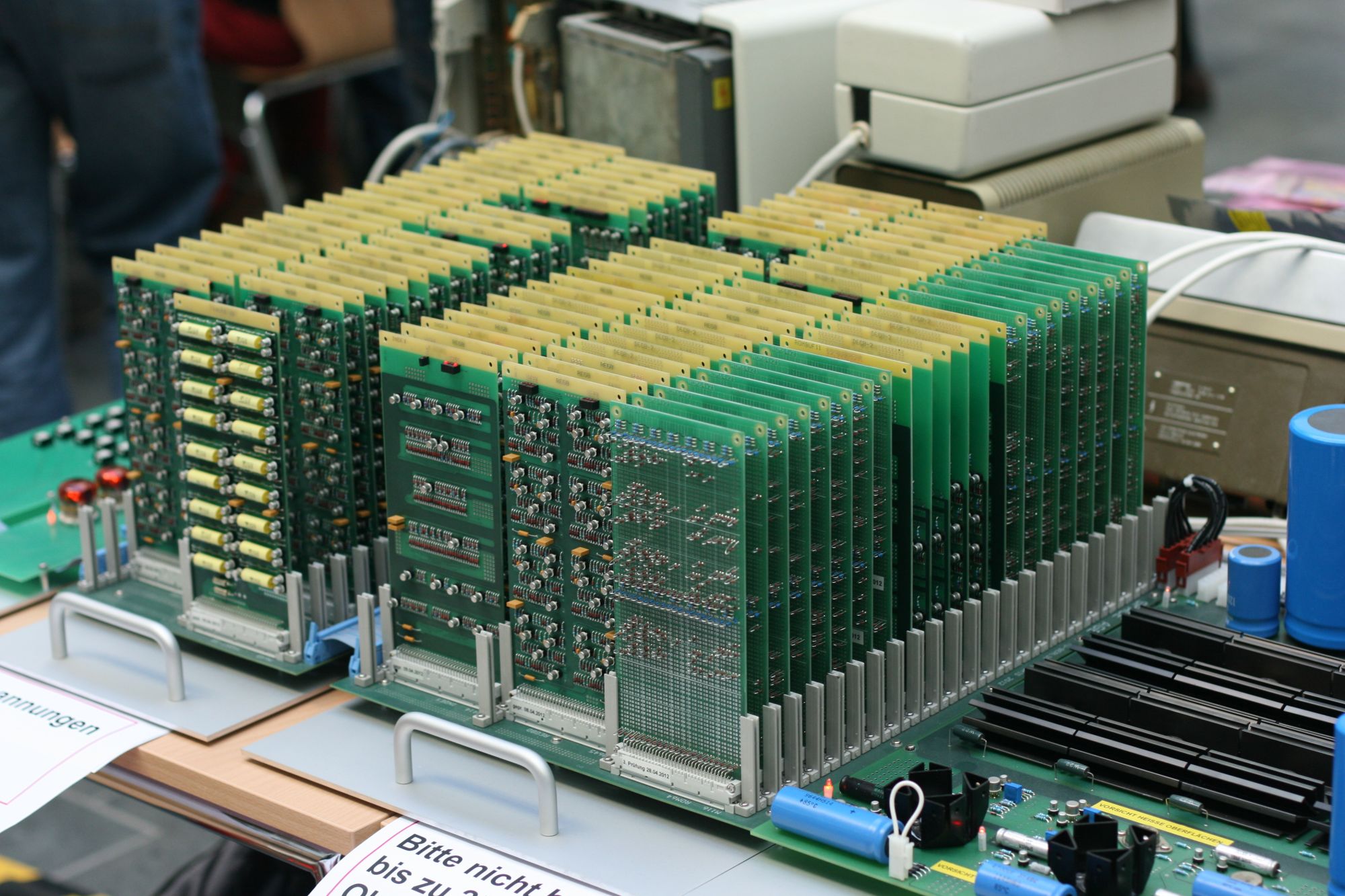
(That's not a complete computer, it's just a 4-bit CPU that some guy built because he was bored.)
Reply
0
0
10-28-2015, 12:50 PM
SADFab Destructive Testing Engineer
iTrader: (5)
Join Date: Apr 2014
Location: Beaverton, USA
Posts: 18,642
Total Cats: 1,866
I don't know anyone that designs purely in schematic mode, just because of the time consuming aspect of it. But the cool thing about VHDL is that you are actually just describing hardware. And the hardware comes out differently each way you design it. So by good design practices, and not being wasteful you can get very close to a perfectly efficient design.
There are also entire groups and teams dedicated to schematic design optimization. And I'm sure the software is progressing every day.
There are also entire groups and teams dedicated to schematic design optimization. And I'm sure the software is progressing every day.
Reply
0
0
10-28-2015, 01:11 PM
Boost Pope
iTrader: (8)
Join Date: Sep 2005
Location: Chicago. (The less-murder part.)
Posts: 33,023
Total Cats: 6,591

That whole group is gone now, and I'm sure if they were still around there'd be a lot more automation. When we got into the latter Xilink designs (when we started implementing whole microcontrollers in the fabric) we did actually start licensing IP cores and dropping them in. But the core of the design, where the actual audio processing took place, that was pure schematic all the way until the very end. Nobody made IP cores to do that stuff, and even the young guy on the team (about my age) felt more comfortable doing DSP in schematic as compared to code.
Actually, now that I think about it, the very last product we designed broke from the FPGA mold. We still used gate-arrays as glue, but we switched to a DSP chip made by TI to do the audio in. So that, obviously, was coded.
Reply
0
0
10-28-2015, 01:45 PM
Senior Member
iTrader: (2)

Join Date: Sep 2009
Location: Edmonton, AB, Canada
Posts: 1,193
Total Cats: 29
In the last 3 weeks I hired 4 new guys and just sent the wire transfer for our "new to us" boomtruck. A 2003 Kenworth T800, ready to go. I just have to get it over to our sign guy and have the logos put on.
It took a few years, but it feels great to finally have things turn out so well. Hoping to keep it going like this for another 50 years to come!
It took a few years, but it feels great to finally have things turn out so well. Hoping to keep it going like this for another 50 years to come!
I'm still hoping for the day I can own a skidsteer ..........mmmmm salivating....
Reply
0
0


 10-28-2015, 03:13 PM
Back in the 60's we were the first ones with a crane truck, first concrete pump in CT, had our own ready mix plant and mixers, excavators, etc etc. Company grew too big and they ended up just keeping the foundation company open. I'm probably one of the last of the Americans in the business, at least in our area. The other guys are old and tired and the rest no speak English. Perfect scenario to monopolize the market and it's starting to happen.

Reply
0
0


