Problem RPM signal MS2
 07-02-2016, 09:21 AM
#1
Newb
Thread Starter

Join Date: May 2016
Posts: 3
Total Cats: 0
I have received an MS2 from someone with a '92 1.6 NA MX5, which I'm trying to adapt for my '94 1.8 MX5. He gave it to me because there was a problem with it, it would get (almost) no RPM signal (apparently it would not get above 120 rpm on JimStim, no idea if it got any signal on the car). I am trying to check everything to see where the mistake might be, he used the MiataTurbo wiki page to build the MS2. So far, I have found 1 thing that looked interesting. The MS2 is a DIY unit from diyautotune, with a wiring harness to connect the DB37 on the MS2 to the ECU connector in the car. In this wiring harness is a protected pair used for the RPM signal, which includes a positive and negative lead, and shielding. On the wiki page I found this diagram:

However, the diyautotune harness uses this diagram, which shows a difference in the ground wires only:
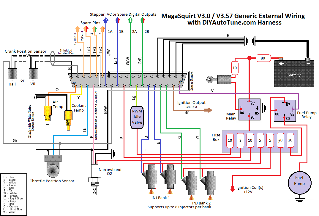
Now my question. The negative of the CKP (or CPS or RPM signal) wires is connected on pin 1 in the DB37 connector, but it is not connected to the connector used to plug it into the cars harness. I would like to ask you if any of you know what should be done with this negative wire. Should it:
A ) not be connected at all since it is not used (which would mean the wiring is correct as it is).
B ) be connected to the same place as the other ground wires.
C ) be connected somewhere else.
I've searched just about everywhere but cannot find an answer. I'm hoping since it is your wiki that was used to construct the MS2 you might know what should be done with this wire.
Thank you for your support.
However, the diyautotune harness uses this diagram, which shows a difference in the ground wires only:
Now my question. The negative of the CKP (or CPS or RPM signal) wires is connected on pin 1 in the DB37 connector, but it is not connected to the connector used to plug it into the cars harness. I would like to ask you if any of you know what should be done with this negative wire. Should it:
A ) not be connected at all since it is not used (which would mean the wiring is correct as it is).
B ) be connected to the same place as the other ground wires.
C ) be connected somewhere else.
I've searched just about everywhere but cannot find an answer. I'm hoping since it is your wiki that was used to construct the MS2 you might know what should be done with this wire.
Thank you for your support.

Reply
 0
0

0
 07-05-2016, 02:43 PM
#3
Newb
Thread Starter
Join Date: May 2016
Posts: 3
Total Cats: 0
So you are saying, even if I do not solder the wire coming from pin 1 to the ground, it will still be connected to the sensor ground through pin 7 which is soldered, because they connect to each other on the MS2 pcb?
Hmm, well, at least that eliminates one possibility, thank you.
Hmm, well, at least that eliminates one possibility, thank you.
Reply
0
0
07-05-2016, 03:30 PM
#4
Boost Czar


iTrader: (62)
Join Date: May 2005
Location: Chantilly, VA
Posts: 79,490
Total Cats: 4,079
use the official DIYAUTOTUNE.com DIYPNP documentation. Not random DIY MS2 documentation of the world's shittiest diagram or MS3 documentation.
This documents the assemble and difference between the connector board jumpers:
https://www.diyautotune.com/support/...3-mazda-miata/
https://www.diyautotune.com/support/...5-mazda-miata/
This documents the assemble and difference between the connector board jumpers:
https://www.diyautotune.com/support/...3-mazda-miata/
https://www.diyautotune.com/support/...5-mazda-miata/
Reply
0
0

Thread
Thread Starter
Forum
Replies
Last Post
douginjenison
Miata parts for sale/trade
7
08-17-2016 03:18 PM
the_enginear
Build Threads
238
07-16-2016 07:35 AM


