DIYPNP on a 99
 09-03-2009, 06:35 PM
#1
Supporting Vendor


Thread Starter
iTrader: (33)
Join Date: Jul 2006
Location: atlanta-ish
Posts: 12,659
Total Cats: 134
This thread will discuss the trials and tribulations of installing DIY Autotune's "DIYPNP" engine management system on a 99 miata.
For brevity, I am going to assume that if you're reading this, you're already familiar with Megasquirt hardware and the DIYPNP. My car is a 99 with a Bell Engineering S4 turbo system/Garrett GT2560r, GM LSx coil near plug ignition, and a 3" exhaust by Enthuza.
I am hopeful that when completed, this endeavor can be cleaned up and be used as a walk-thru for people to follow. Obviously building the first units, and getting any bugs out, is going to be the hard part. Once the system is down, it more or less can be copied.
Some pictures
This is what you have when you open the box. Starting at about 4 o'clock are the bare adapter boards. These are the boards that we will be installing components on. The boards are simply an inteface between the vehicle and the neat little white board in the center. The white board is a MicroSquirt unit. The Microsquirt is the actual computer, and is ready built. Going clockwise from our boards at 4:00 the black thing is a very nice aluminum housing to enclose our DIYPNP once completed. Keep going and you see the housing's endplates. From 11:00 to 3:00 is all components we will use to populate the boards. The pink items are special anti static bags that more sensitive electronics are stored in. The items contained therein should be treated with appropriate care. The items in the clear bags are resistors, diodes, capacitors, and some headers and adapters. There's a lot of stuff. And we'll use most of it.

Here's the heart of it, the MicroSquirt module

All the bags are well labeled. The packaging in general is quite impressive. You can tell a lot of thought and care was given.


These next 2 items are optional, but more or less mandatory.
The top item is a basic power supply. All it does is power the MS unit (once you've finished it) before installing it in the car. Makes it easier to flash the firmware into the unit since you can do it all at your desk and in the a/c. OK, you could technically do without it, but on the later cars, since the computer goes up in the dash, it's a PITA to access it. So the more work you can do inside, the better.
The bag is a kit for a new intake air temp sensor. This is necessary because we'll be eliminating the factory MAF. Intake air temp is necessary for fueling calculations--and has some involvment in ignition trim as well under certain circumstances. Furthermore, the more advanced and option firmware we'll be installing on the MS does not support MAF (a less advanced firmware does, but it gives up other features that we actually want to keep). So it's a necessity.

For brevity, I am going to assume that if you're reading this, you're already familiar with Megasquirt hardware and the DIYPNP. My car is a 99 with a Bell Engineering S4 turbo system/Garrett GT2560r, GM LSx coil near plug ignition, and a 3" exhaust by Enthuza.
I am hopeful that when completed, this endeavor can be cleaned up and be used as a walk-thru for people to follow. Obviously building the first units, and getting any bugs out, is going to be the hard part. Once the system is down, it more or less can be copied.
Some pictures
This is what you have when you open the box. Starting at about 4 o'clock are the bare adapter boards. These are the boards that we will be installing components on. The boards are simply an inteface between the vehicle and the neat little white board in the center. The white board is a MicroSquirt unit. The Microsquirt is the actual computer, and is ready built. Going clockwise from our boards at 4:00 the black thing is a very nice aluminum housing to enclose our DIYPNP once completed. Keep going and you see the housing's endplates. From 11:00 to 3:00 is all components we will use to populate the boards. The pink items are special anti static bags that more sensitive electronics are stored in. The items contained therein should be treated with appropriate care. The items in the clear bags are resistors, diodes, capacitors, and some headers and adapters. There's a lot of stuff. And we'll use most of it.
Here's the heart of it, the MicroSquirt module
All the bags are well labeled. The packaging in general is quite impressive. You can tell a lot of thought and care was given.
These next 2 items are optional, but more or less mandatory.
The top item is a basic power supply. All it does is power the MS unit (once you've finished it) before installing it in the car. Makes it easier to flash the firmware into the unit since you can do it all at your desk and in the a/c. OK, you could technically do without it, but on the later cars, since the computer goes up in the dash, it's a PITA to access it. So the more work you can do inside, the better.
The bag is a kit for a new intake air temp sensor. This is necessary because we'll be eliminating the factory MAF. Intake air temp is necessary for fueling calculations--and has some involvment in ignition trim as well under certain circumstances. Furthermore, the more advanced and option firmware we'll be installing on the MS does not support MAF (a less advanced firmware does, but it gives up other features that we actually want to keep). So it's a necessity.

Reply
 0
0

0
09-03-2009, 06:35 PM
#2
Supporting Vendor
Thread Starter
iTrader: (33)
Join Date: Jul 2006
Location: atlanta-ish
Posts: 12,659
Total Cats: 134
So after you get everything opened and organized, it's a matter of simply starting the assembly instructions. First thing is to populate the adapter boards. You start with the resistors, then go to the diodes. It's really just a matter of matching up. You open a bag, and install it's contents into the slot stated on the bag's label. Just match it up to the right area on the board. Once you have all the resistors and diodes installed on the board, flip it upside down and solder them all down. The only thing to watch for is diodes have polarity; they go a certain way. So you make sure you face them correctly. It's all labeled and would be pretty tough to screw up.
Here's what my board now looks like, with the resistors and diodes soldered in.

This is a time consuming process. I'll say this now. If you're looking for some instant gratification, this is probably not a solution for you. If you're willing and wanting to put some work in, sacrificing time for money, but also learning and understanding how this machine works... well, then this is for you. Getting to this point (opening the box, sorting the hardware, reading through the entire assembly instructions, then assembling it to this early stage) probably took 2 hours--and I'd imagine that I got here faster than most would.
There is still a lot to be done. Tomorrow I'll start mapping out what features I want and assigning inputs and outputs.
Here's what my board now looks like, with the resistors and diodes soldered in.
This is a time consuming process. I'll say this now. If you're looking for some instant gratification, this is probably not a solution for you. If you're willing and wanting to put some work in, sacrificing time for money, but also learning and understanding how this machine works... well, then this is for you. Getting to this point (opening the box, sorting the hardware, reading through the entire assembly instructions, then assembling it to this early stage) probably took 2 hours--and I'd imagine that I got here faster than most would.
There is still a lot to be done. Tomorrow I'll start mapping out what features I want and assigning inputs and outputs.
Reply
0
0
09-03-2009, 06:37 PM
#3
Supporting Vendor
Thread Starter
iTrader: (33)
Join Date: Jul 2006
Location: atlanta-ish
Posts: 12,659
Total Cats: 134
Consider these time lapse progress pics. I increased the resolution so they would be larger. All we're doing here is continuing to follow the assembly instructions.
More components installed. We're getting to higher level components, but it's all the same--match up carefully and solder in. MAP sensor is top left. We're going with a standard 2.5 bar to start with. If I free up some IO downroad, I'll go with dual 2.5 bars or mapdaddy dual 4 bar (dual sensors for real time baro correction). I held it down with (included) nylon bolts and nuts to make sure it wouldn't shift out of position when soldering. They're already removed before the pic was taken.


Now I've installed the DB9 & DB15 connectors, the 12V port (for powering on bench with the adapter pictured above), and 2 of the spark output drivers. I recommend doing the 12V port first because it's shorter than the DB connectors. Unless you have some custom plans, you only should solder 4 pins on the DB9. Just follow the traces to determine which 4. 5 pins won't have traces, so there's no reason to solder them. You could get away with not wiring up the DB15. It's there to allow I/O of custom or additional circuits without having to modify your factory harness. I went ahead and soldered them all up, adds as much flexibility as possible downroad.
You'll notice I've only installed 2 of the spark output transistors. I did this for a reason. I wanted to show this for anyone running stock ignition as they will only need these 2 outputs.

Now the board is pretty much completed. I went ahead and installed the transistors for spark 3 & 4, as well as transistors for boost control and a 5V regulated power supply. The transistors are installed on a heat sink and bolted through the board. You want to make sure that the heatsinks do not contact each other.


And here it is with the microsquirt module attached

I have flashed in B&G firmware and it communicates with MegaTune. However I am unable to flash Extra firmware. I don't know why.
More components installed. We're getting to higher level components, but it's all the same--match up carefully and solder in. MAP sensor is top left. We're going with a standard 2.5 bar to start with. If I free up some IO downroad, I'll go with dual 2.5 bars or mapdaddy dual 4 bar (dual sensors for real time baro correction). I held it down with (included) nylon bolts and nuts to make sure it wouldn't shift out of position when soldering. They're already removed before the pic was taken.
Now I've installed the DB9 & DB15 connectors, the 12V port (for powering on bench with the adapter pictured above), and 2 of the spark output drivers. I recommend doing the 12V port first because it's shorter than the DB connectors. Unless you have some custom plans, you only should solder 4 pins on the DB9. Just follow the traces to determine which 4. 5 pins won't have traces, so there's no reason to solder them. You could get away with not wiring up the DB15. It's there to allow I/O of custom or additional circuits without having to modify your factory harness. I went ahead and soldered them all up, adds as much flexibility as possible downroad.
You'll notice I've only installed 2 of the spark output transistors. I did this for a reason. I wanted to show this for anyone running stock ignition as they will only need these 2 outputs.
Now the board is pretty much completed. I went ahead and installed the transistors for spark 3 & 4, as well as transistors for boost control and a 5V regulated power supply. The transistors are installed on a heat sink and bolted through the board. You want to make sure that the heatsinks do not contact each other.
And here it is with the microsquirt module attached
I have flashed in B&G firmware and it communicates with MegaTune. However I am unable to flash Extra firmware. I don't know why.
Reply
0
0

 09-04-2009, 11:54 PM
#7
Slowest Progress Ever
iTrader: (26)
Join Date: Oct 2007
Location: The coal ridden hills of Pennsylvania
Posts: 6,022
Total Cats: 304
So Ben, do you have your '99 running with this unit? I was awaiting someone to buy one of these and post this similar thread, but I didn't expect it to be this soon. Keep us up to date!
Reply
0
0
09-05-2009, 08:45 AM
#8
Supporting Vendor
Thread Starter
iTrader: (33)
Join Date: Jul 2006
Location: atlanta-ish
Posts: 12,659
Total Cats: 134
The adap does look like a really nice unit. But this is under half the price.
Car's not ready to run yet, but it's not too far off. One of my holdups is I ran out of 20ga wire that's included with the kit. The smallest I have here is 16ga, which is a PITA to run to the small holes in the board. I went ahead and ran 16ga for power and ground, but it wasn't very fun. And some of the pins I need to connect to (at the db15) are super super small.
I need to build an alternator control circuit and the Joe/Abe cam/crank input circuit (which is a lot harder and more involved than just adding a pull down, but the experiences I've read from others make me want to do it). I'm going to Fry's for the components and some wire. I'm thinking I'll have it done by the end of the weekend... maybe. I don't want to jinx myself.
Reply
0
0
09-05-2009, 08:53 AM
#9
Supporting Vendor
Thread Starter
iTrader: (33)
Join Date: Jul 2006
Location: atlanta-ish
Posts: 12,659
Total Cats: 134
The firmware problem is straightened out. I kept flashing, and eventually it loaded.
So here's where we are now. If you are following, you'll see that the MAP sensor is secured with nylon hardware. I've also added the boot jumper which is on the bottom right corner next to "input 1". It's the thingie with the 2 legs sticking up. Take note of it because it's position because it's not labeled on the board. When you need to actually short the BJ pins together, it came with a little shunt, which is a cap that connects the two pins. You'll also notice the endplate is installed.

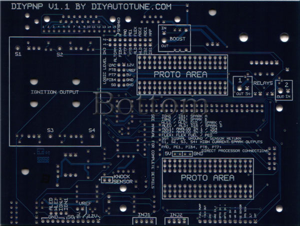
Here's our adapter board. It's the interface between the megasquirt system and our vehicle's harness. What we'll do later is break out the wires we need to use on the factory harness, then jumper them to the megasquirt board. IE "Inj 1" on the megasquirt is jumped to the wires in the factory harness that go to injection bank 1. And so on. But there are a couple circuits we will build first, so we're not there yet.

This is what the finished product looks like. I applied the decal to give it a gansta lean for some flava. We're not done, I just thought it would be cool to see what it looks like. When you slide the board into the case, it goes on the rung that is 1 from the bottom.


This side has the connections for desktop power, db9 serial interface to computer, and db15 expansion. The db15 is there to allow extra wiring to go in and out of the MS to your car for anything that's not provisioned on your factory harness. Notice how the lugs for the serial connections are screwed through the endplate. I used a 3/16" midget wrench.


This is the other end. Your factory harness plugs in here.

So here's where we are now. If you are following, you'll see that the MAP sensor is secured with nylon hardware. I've also added the boot jumper which is on the bottom right corner next to "input 1". It's the thingie with the 2 legs sticking up. Take note of it because it's position because it's not labeled on the board. When you need to actually short the BJ pins together, it came with a little shunt, which is a cap that connects the two pins. You'll also notice the endplate is installed.
Here's our adapter board. It's the interface between the megasquirt system and our vehicle's harness. What we'll do later is break out the wires we need to use on the factory harness, then jumper them to the megasquirt board. IE "Inj 1" on the megasquirt is jumped to the wires in the factory harness that go to injection bank 1. And so on. But there are a couple circuits we will build first, so we're not there yet.
This is what the finished product looks like. I applied the decal to give it a gansta lean for some flava. We're not done, I just thought it would be cool to see what it looks like. When you slide the board into the case, it goes on the rung that is 1 from the bottom.
This side has the connections for desktop power, db9 serial interface to computer, and db15 expansion. The db15 is there to allow extra wiring to go in and out of the MS to your car for anything that's not provisioned on your factory harness. Notice how the lugs for the serial connections are screwed through the endplate. I used a 3/16" midget wrench.
This is the other end. Your factory harness plugs in here.
Reply
0
0
09-05-2009, 09:18 AM
#10
Supporting Vendor
Thread Starter
iTrader: (33)
Join Date: Jul 2006
Location: atlanta-ish
Posts: 12,659
Total Cats: 134
Now we're breaking out connections from the MS to the adapterboard.
This is what I got from the FSM

And how I'm assigning I/O

And what that looks like. Not all the connections are made because I'm out of wire. But it's mostly done.

It appears to me that when you push the A/C button on the climate control panel, 1P on the PCM is pulled to ground (through the pressure switch). When 1P goes to ground, the PCM grounds the compressor and a/c fan relay coils through 1S and 1I respectively. What this means is that A/C control will be pretty easy--and can be done without using an input on the MS. Just jump these 3 pins.
I need to find the tach input to the cluster.
This is what I got from the FSM
And how I'm assigning I/O
And what that looks like. Not all the connections are made because I'm out of wire. But it's mostly done.
It appears to me that when you push the A/C button on the climate control panel, 1P on the PCM is pulled to ground (through the pressure switch). When 1P goes to ground, the PCM grounds the compressor and a/c fan relay coils through 1S and 1I respectively. What this means is that A/C control will be pretty easy--and can be done without using an input on the MS. Just jump these 3 pins.
I need to find the tach input to the cluster.
__________________
91 Turbo | 10AE Turbo | 01 Track Rat | #323 Mazda Champcar
Chief of Floor Sweeping, DIYAutoTune.com & AMP EFI
Crew Chief, Car Owner & Least Valuable Driver, HongNorrthRacing
Last edited by Ben; 09-07-2009 at 04:39 PM. Reason: update pinout
Reply
0
0
09-05-2009, 10:37 AM
#11
Supporting Vendor
Thread Starter
iTrader: (33)
Join Date: Jul 2006
Location: atlanta-ish
Posts: 12,659
Total Cats: 134
OK, dealing with CMP and CKP conditioning is frustrating me.
I think the alternator control circuit is on lock down. Jason C designed this (picture is M@ Y8's board)

I think the alternator control circuit is on lock down. Jason C designed this (picture is M@ Y8's board)
Reply
0
0
09-05-2009, 02:11 PM
#12
Supporting Vendor
Thread Starter
iTrader: (33)
Join Date: Jul 2006
Location: atlanta-ish
Posts: 12,659
Total Cats: 134
So you kiddies can follow along.
With engine off,
Cam sensor has 5V on the GY/L (gray/blue stripe) pin 2H
Crank sensor has 12V on the GY/R (gray/red stripe) pin 2J
IAC has 12V on the O (orange) pin 3M
Also I saw a mistake in my pinout... I mixed up an I with L. +5V for sensors is on pin 2I LG/R. It's not 2L. 2L is MAF input.
With engine off,
Cam sensor has 5V on the GY/L (gray/blue stripe) pin 2H
Crank sensor has 12V on the GY/R (gray/red stripe) pin 2J
IAC has 12V on the O (orange) pin 3M
Also I saw a mistake in my pinout... I mixed up an I with L. +5V for sensors is on pin 2I LG/R. It's not 2L. 2L is MAF input.
Reply
0
0
09-05-2009, 09:42 PM
#13
Supporting Vendor
Thread Starter
iTrader: (33)
Join Date: Jul 2006
Location: atlanta-ish
Posts: 12,659
Total Cats: 134
Got some more 20ga wire today so I could continue jumpering. Started getting into the 'fun' stuff, like I wired the clutch switch in (through input 1 and then to flex) for clutch-activated launch control. I was going to put a toggle switch on the line, but I couldn't find a panel on my car I wanted to drill to install it. My 10AE carbon fiber is too pretty. 


I'm knockin down the list. Not everything listed will get connected, but the items marked to the left are all connected per the pinouts above.

Forgot to pick up some real small gauge wire to get the db15 breakout wired up. The pins for the db15 are really really small. Looks like maybe 24ga will be the ticket. I'm half tempted to grab some cat5 from a spool in the garage.
These are the things I need to bring in/out of the uS via the db15:
Intake air temp (got a GM sensor from DIY Autotune)
wideband o2
spark C and spark D for when we go individual fire ignition
2 inj outputs for when we go sequential injection. yes, you read that right
An extra ground line or two or three
boost control
and maybe knock. Not sure if I should use knocksenseMS with the motor mount knock sensor (which I have) or if I should use the oem sensor and wiring. I'm leaning towards the knocksense.
When I'm done I'll give a real nice pin out of everything. Make it super simple for anyone to just copy.
I'm knockin down the list. Not everything listed will get connected, but the items marked to the left are all connected per the pinouts above.
Forgot to pick up some real small gauge wire to get the db15 breakout wired up. The pins for the db15 are really really small. Looks like maybe 24ga will be the ticket. I'm half tempted to grab some cat5 from a spool in the garage.
These are the things I need to bring in/out of the uS via the db15:
Intake air temp (got a GM sensor from DIY Autotune)
wideband o2
spark C and spark D for when we go individual fire ignition
2 inj outputs for when we go sequential injection. yes, you read that right
An extra ground line or two or three
boost control
and maybe knock. Not sure if I should use knocksenseMS with the motor mount knock sensor (which I have) or if I should use the oem sensor and wiring. I'm leaning towards the knocksense.
When I'm done I'll give a real nice pin out of everything. Make it super simple for anyone to just copy.
Reply
0
0
 09-06-2009, 07:35 AM
#15
Supporting Vendor
Thread Starter
iTrader: (33)
Join Date: Jul 2006
Location: atlanta-ish
Posts: 12,659
Total Cats: 134
You are correct, thanks Frank.
I apparently looked at the 95 wiring diagram for the grounds. I just looked at the 99 diagram and I see main ground on 3A 3B and sensor ground on 3C. I appreciate that heads up.
Also, nice wiring diagram.
I apparently looked at the 95 wiring diagram for the grounds. I just looked at the 99 diagram and I see main ground on 3A 3B and sensor ground on 3C. I appreciate that heads up.
Also, nice wiring diagram.
Reply
0
0
09-06-2009, 12:39 PM
#16
Senior Member

Join Date: Nov 2007
Location: Belgium
Posts: 999
Total Cats: 73
I'm not sure what kind of ground 3C is, but you were right about sensor ground in your write up, it's 3F. Not that it matters really, most folks connect them all together in the DB37 so the sensors see ground potential from the MS. I'm still not convinced this is the best way to do it, but until we know how the ground plane from the MS is routed, it's the only way to do it. Internally, there's 2 seperate ground planes in the MS, but it appears that nobody knows which pin is which.
Reply
0
0
09-06-2009, 01:41 PM
#17
Supporting Vendor
Thread Starter
iTrader: (33)
Join Date: Jul 2006
Location: atlanta-ish
Posts: 12,659
Total Cats: 134
3C is an additional sensor ground pin. The way I read it, 3F goes to the sensors, then the sensors tie together and hit 3C, then 3C goes to the engine.
Something interesting to note here is that the sensor ground ties to coil power ground. I'm running LSx coils (which have individual pinouts for sensor and power ground), so I'm going to run my own grounding accordingly.

Sensor ground and power ground are distinctly separated on my mainboard. Whatever they do from there, I don't know, but I'll do my best do do it right on my end, assuming they did it right on theirs.
Something interesting to note here is that the sensor ground ties to coil power ground. I'm running LSx coils (which have individual pinouts for sensor and power ground), so I'm going to run my own grounding accordingly.
Sensor ground and power ground are distinctly separated on my mainboard. Whatever they do from there, I don't know, but I'll do my best do do it right on my end, assuming they did it right on theirs.
Code:
        ^ pwr grnd
              ^ sensor ground (SG)
__________________
91 Turbo | 10AE Turbo | 01 Track Rat | #323 Mazda Champcar
Chief of Floor Sweeping, DIYAutoTune.com & AMP EFI
Crew Chief, Car Owner & Least Valuable Driver, HongNorrthRacing
Last edited by Ben; 09-06-2009 at 02:18 PM.
Reply
0
0
09-07-2009, 04:37 PM
#19
Supporting Vendor
Thread Starter
iTrader: (33)
Join Date: Jul 2006
Location: atlanta-ish
Posts: 12,659
Total Cats: 134
Added a few more jumpers and built the DB15 harness. Used 24ga solid wire to jump the DB15 pins on the mainboard. Tied in the sensor grounds as described. I decided to bring 2 extra main grounds out at pins 1&2 and an extra sensor ground at pin 3. Can't hurt. I think I'll also bring 12V switched at pin 8 just in case.
I haven't done anything about the knock sensor. The standard knocksense circuit is built on the main board, but it's not jumpered in. I also have a knocksenseMS. I need to decide which system to go with. I don't know if one is better than the other.
Still haven't done anything with cam or crank signals, or alternator control.
Reply
0
0
09-13-2009, 12:26 AM
#20
Supporting Vendor
Thread Starter
iTrader: (33)
Join Date: Jul 2006
Location: atlanta-ish
Posts: 12,659
Total Cats: 134
Success!
The car runs. I am using the stock uS trigger inputs. Crank is wired to opto - and has a 470 ohm pullup on opto + to 12V. Cam has a 470 ohm pull up to 5V. No schmitt nonsense. No drama.
Shot huge fireballs out the tailpipes getting it started the first few times. It was waaayyy too rich.
Jason C's alternator control circuit is functional. I'm getting 13.5V. A couple of the resistor values were close to what Jason specified, but not exact. I did the best I could with what was available at Fry's.
I put about 20 miles on the car, starting to hammer down the VE table. Need to work on cranking enrichments.
Over the next few days I'll get it street tuned nicely, then get into neat stuff like sequential injection, individual spark, and electronic boost control to aid spool. Need to also add a/c control. Matt Cramer said to wire it through one of the digital inputs, a/c command button on the in side and the a/c relays on the out side. One of the resistors has to be burned off, but he didn't say which. He also said that using 2 diodes, an NPN and a PNP, like I outlined in my other thread would work.
Reply
0
0


