I've got some major MS1 HARDWARE issues

 01-01-2011, 10:24 PM
#3

i thought the injectors got the voltage from the megasquirt?
fwiw my car was running on two cylinders intermittently because of a wiring harness issue. I had a cold solder joint which ended up breaking due to too much jostling, and would, by chance, be connected most of the time except when it decided two cylinders are more fun than 4.
have you done a visual inspection of your wiring harness & MS PCB?
Tomaj

Reply
 0
0

0
01-01-2011, 10:29 PM
#4
Yes, I've inspected both. The board looks fine, as does the harness. My guess though is since it only happened when I move the box that it has something to do with the harness getting jostled.
And the injectors get 12V from the board... you're right. I may rewire all the 12V's to run on their own relay direct to the battery. Not only will that give them a more solid 12V it should solve my problem as well.

And the injectors get 12V from the board... you're right. I may rewire all the 12V's to run on their own relay direct to the battery. Not only will that give them a more solid 12V it should solve my problem as well.
Reply
0
0
01-01-2011, 11:48 PM
#7
Boost Pope


iTrader: (8)
Join Date: Sep 2005
Location: Chicago. (The less-murder part.)
Posts: 33,020
Total Cats: 6,588
They shouldn't.
This may not be relevant or helpful, but for background, the injectors get their +12 from the main relay via the White/Red wire. That wire also supplies +12 to the ECU, but the point is that the voltage isn't coming from the ECU and is merely branched out to the ECU harness. You can pull the ECU out entirely and the injectors will still have +12 on them so long as the main relay is functioning and the key is on.
This may not be relevant or helpful, but for background, the injectors get their +12 from the main relay via the White/Red wire. That wire also supplies +12 to the ECU, but the point is that the voltage isn't coming from the ECU and is merely branched out to the ECU harness. You can pull the ECU out entirely and the injectors will still have +12 on them so long as the main relay is functioning and the key is on.
Reply
0
0
01-02-2011, 12:01 AM
#8
Ok.. thanks for the info. I was just reading the schematics and it made it 'look' like they were getting power from the ECU.
So if they are getting power from elsewhere, and this problem is only happening when I move the box around the issue is obviously something else. The car ran fine yesterday until I decided to pull the ECU and re-route my AIT wiring. Now it's all fucked up again..
So if they are getting power from elsewhere, and this problem is only happening when I move the box around the issue is obviously something else. The car ran fine yesterday until I decided to pull the ECU and re-route my AIT wiring. Now it's all fucked up again..
Reply
0
0

 01-02-2011, 03:30 PM
#13

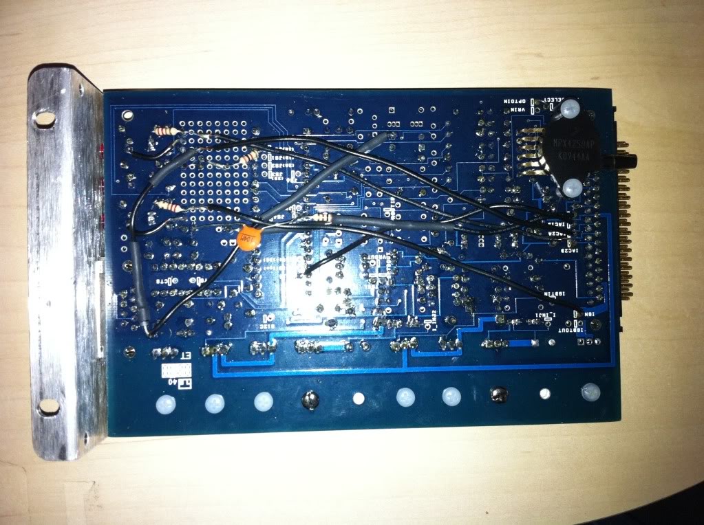
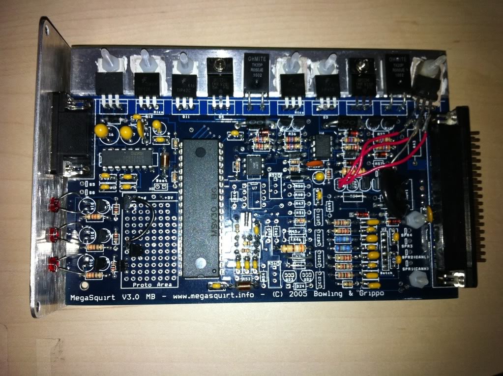
Sounds like something is grounding out to the case that shouldn't be. Check the transistors on the heatsink that are related to the injector circuit. I dont remember if they need a mica insulator or not but if they do check continuity between the tab and the heatsink. If they are supposed to be insulated then there should be no continuity. I had a problem with mine where even though I used a mica insulator there was still continuity on one of the transistors. Although I don't remember which anymore.
Useful link for figuring out whats what:
http://www.megamanual.com/ms2/pcb.htm
Useful link for figuring out whats what:
http://www.megamanual.com/ms2/pcb.htm
Reply
0
0
 01-02-2011, 04:14 PM
#16
I've inspected my patch harness and pulled on all the connections. Also, nothing is touching. The blue injector wire and teh white with green stripe on the DB37 are extremely close but they aren't touching. Unless power can arc between them, I'm pretty sure that's no the issue.
Reply
0
0
01-02-2011, 05:50 PM
#18
Elite Member
iTrader: (10)
Join Date: Jun 2006
Location: Athens, Greece
Posts: 5,976
Total Cats: 355
I would verify that the MS1 chip sits firmly in place and if need be, I would reflash the firmware.
Reply
0
0
01-02-2011, 05:54 PM
#19
I just checked the voltage at the injector clips with the key in ACC with my multimeter
inj 1 - 00.01
inj 2 - 11.56
inj 3 - 00.01
inj 4 - 11.56
So the injectors 2/4 are getting almost 12V of power when the engine isn't even cranking.
I already took a look at the box, and everything looks solid. Something is grounding injectors 2/4.
As for firmware, I don't exactly know how to do that.
inj 1 - 00.01
inj 2 - 11.56
inj 3 - 00.01
inj 4 - 11.56
So the injectors 2/4 are getting almost 12V of power when the engine isn't even cranking.
I already took a look at the box, and everything looks solid. Something is grounding injectors 2/4.
As for firmware, I don't exactly know how to do that.
Last edited by falcon; 01-02-2011 at 06:05 PM.
Reply
0
0
01-02-2011, 06:14 PM
#20
Boost Pope
iTrader: (8)
Join Date: Sep 2005
Location: Chicago. (The less-murder part.)
Posts: 33,020
Total Cats: 6,588
Where are you taking this measurement, exactly? IOW, did you unplug the connectors from the injectors and measure at the plug?
Here's the deal: none of the injectors should be getting power with the key in the ACC position, and all four of the injectors should be getting +12 when the key is in RUN even if the engine is not turning. Power to the injectors comes in via the white/red wire any time they key is in RUN. The ECU then provides a closure to ground for each injector (or each pair, in a banked system) when it wants it to inject.
Your observations in the post above don't appear to make sense to me.
Reply
0
0


