It's been done before but I felt like sharing
 07-24-2008, 04:38 AM
#1
Junior Member
Thread Starter
iTrader: (1)

Join Date: Apr 2008
Location: Bristol
Posts: 439
Total Cats: 0
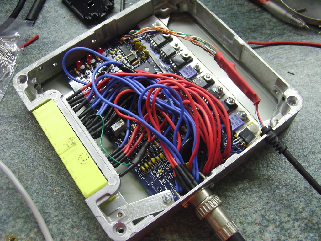
Some pics of my megasquirt. Should be running the car by the weekend, just waiting on an air filter and piece of pipe to put AIT in.
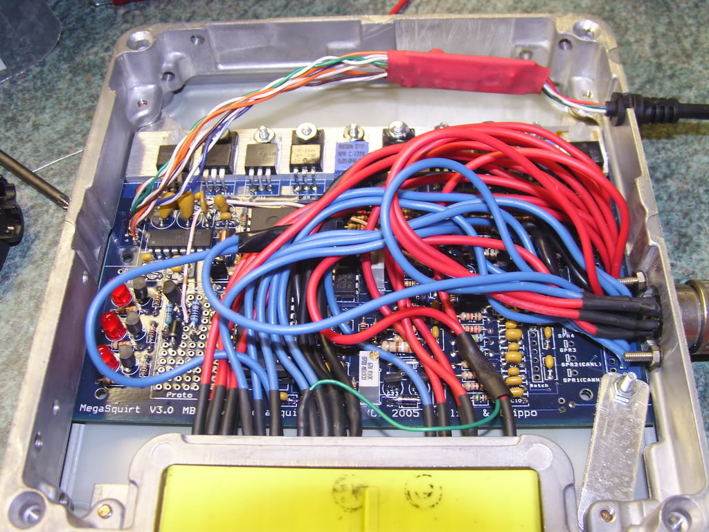
I built it in a stock case as you can see but I added "on board" USB-RS232 communication (the red heatshrinked block at the top) and a nice plug for the LC1 (which is also a great way to power the MS while on my bench)
The (almost) finished product
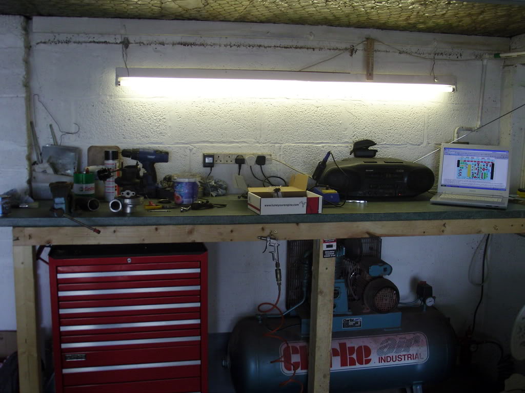
It's nice to have a workbench for toys (sorry I just built it and feel the need to show people)
Box of bits
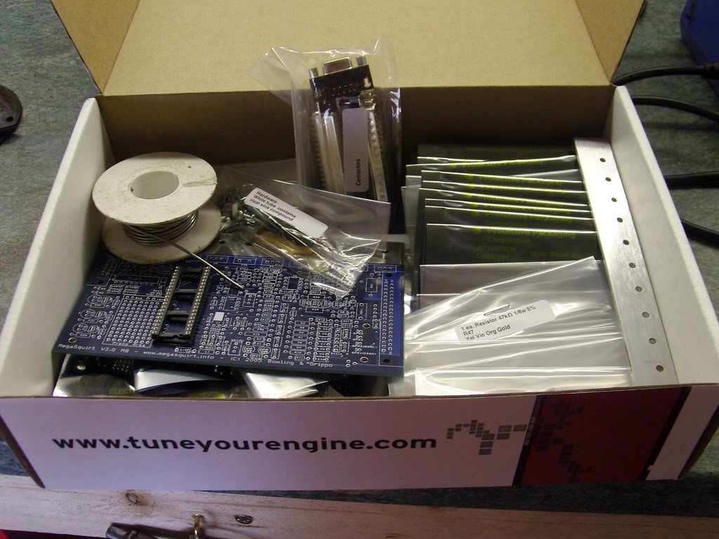
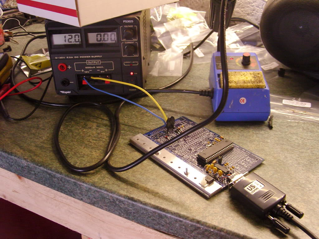
On test after building powersupply and proccessor coms. You can see the el cheepo usb serial adaptor (working so far) that I butchered to go inside.
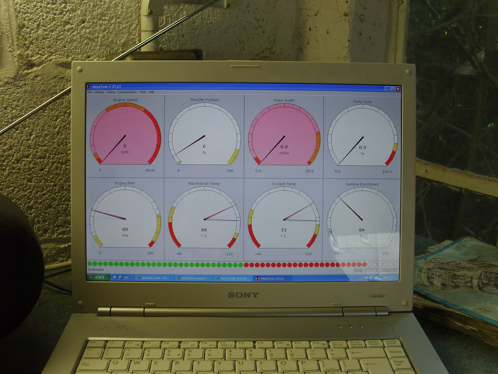
It lives!!
If you are wondering why I went to the effort for this and some of my other mods its because I have an irrational fear of touching the cars wiring. I dont mind repairing it but I really hate it when I buy something and someone have bodged it up in someway. So far everything I have done can be reversed in about 1/2 a day.
I built it in a stock case as you can see but I added "on board" USB-RS232 communication (the red heatshrinked block at the top) and a nice plug for the LC1 (which is also a great way to power the MS while on my bench)
The (almost) finished product
It's nice to have a workbench for toys
(sorry I just built it and feel the need to show people)Box of bits
On test after building powersupply and proccessor coms. You can see the el cheepo usb serial adaptor (working so far) that I butchered to go inside.
It lives!!
If you are wondering why I went to the effort for this and some of my other mods its because I have an irrational fear of touching the cars wiring. I dont mind repairing it but I really hate it when I buy something and someone have bodged it up in someway. So far everything I have done can be reversed in about 1/2 a day.

Reply
 0
0

0


 07-24-2008, 09:53 AM
#7
Junior Member
Thread Starter
iTrader: (1)
Join Date: Apr 2008
Location: Bristol
Posts: 439
Total Cats: 0
Imitation is the highest form of flattery
The BNC connector is actually a locking DIN socket from my audio engineering days. It's a once stop shop for connecting the LC-1 and also a useful way to provide 12v whilst its on the workbench.
I just put all the wires on the DB9 for the hell of it. I was out in the garage and couldn't be bothered to come back in to work out which 3 I needed
Reply
0
0
07-24-2008, 12:33 PM
#8
Boost Pope


iTrader: (8)
Join Date: Sep 2005
Location: Chicago. (The less-murder part.)
Posts: 33,026
Total Cats: 6,592
Duck, my friend, that is an absolutely gorgeous build. The locking circular connector on the side is just pure brilliance, and I love what you did with the built-in RS232 to USB adapter.
I see that the position normally occupied by the MAP sensor is empty. Are you planning to mount the sensor outside of the case, or is it stuck in there somewhere that I didn't see?
Interestingly, here in the states a "DIN" connector is a bit different. They're still circular and polarized, but non-locking. As an example, MIDI and older (8086-80486) computer keyboards use what we call DIN connectors. What you've got there is very similar to what we'd typically call an Aircraft connector, as that style of interconnect is common in high-reliability applications such as airplane wiring harnesses, and also found on pro video equipment such as OB cameras.
Reply
0
0
07-24-2008, 12:50 PM
#9
Junior Member
Thread Starter
iTrader: (1)
Join Date: Apr 2008
Location: Bristol
Posts: 439
Total Cats: 0
Thanks Joe, The MAP isnt mounted yet. Its going to be external connected to . I'm having trouble finding a pinout for the MAP sensor can you hook me up?
The connector is the same as a DIN inside the locking housing, I used them for some of the old PA gear I worked with at school (yes I was the nerd who did all the sound for school productions)
I'm hoping by wiring the LC-1 into the MS itself I will avoid any possibility of ground loops.
Edit: You're quite right, its slightly different to a DIN. Maybe I used it for connecting the light dimmer desks.
The connector is the same as a DIN inside the locking housing, I used them for some of the old PA gear I worked with at school (yes I was the nerd who did all the sound for school productions
) I'm hoping by wiring the LC-1 into the MS itself I will avoid any possibility of ground loops.
Edit: You're quite right, its slightly different to a DIN. Maybe I used it for connecting the light dimmer desks.
Last edited by Duckie_uk; 07-24-2008 at 03:11 PM.
Reply
0
0
07-24-2008, 01:41 PM
#13
Junior Member
Thread Starter
iTrader: (1)
Join Date: Apr 2008
Location: Bristol
Posts: 439
Total Cats: 0
OK hit a brick wall. I need 3 wires for the MAP :(
On the MAF socket there is 12V, MAP sig, AIT sig, GND, SECOND GND, and no more pins for the MAP ref voltage.
Any Ideas? Any way I can use 12v as the ref voltage?
On the MAF socket there is 12V, MAP sig, AIT sig, GND, SECOND GND, and no more pins for the MAP ref voltage.
Any Ideas? Any way I can use 12v as the ref voltage?
Reply
0
0
07-24-2008, 02:10 PM
#14
Junior Member
Thread Starter
iTrader: (1)
Join Date: Apr 2008
Location: Bristol
Posts: 439
Total Cats: 0
I think I may have found it. The right most pin of the MAF socket (light green/black) goes to pin 2F but its also grounded according to the wiring diagram to the rear right of the engine along with 2 other wires. Anyone know where this grounding point is so I can remove it?
Pipe, I found this pic on your original thread
How did you get it to work with only 2 wires?
Mine just registers 100kpa even if I suck on the little nipple :S
Pipe, I found this pic on your original thread
How did you get it to work with only 2 wires?
Mine just registers 100kpa even if I suck on the little nipple :S
Reply
0
0
07-24-2008, 03:28 PM
#15
I didn't, the +5V out should actually read "Wire Pin 3 of MAP sensor to Pin D of AFM". Remember, this diagram is valid for a 1992 car, I am not sure how the 94+ is different. Are you sure the MAF is 12V and not 5V?? If its indeed 12V, share the TPS signal line (+5V) with the MAP sensor. or build a DC-DC converter (one of these perhaps: http://www.maplin.co.uk/Module.aspx?...C=SO&U=strat15) inside your MAP sensor box.
Reply
0
0
 07-24-2008, 04:18 PM
#17
Junior Member
Thread Starter
iTrader: (1)
Join Date: Apr 2008
Location: Bristol
Posts: 439
Total Cats: 0
Aaaawwww I FAIL and it was all going so smoothly 
Does anyone know where the light green/black wire goes to ground? If I can unground it then we have a WIN situation.
http://www.madracki.com/miata/images/wiring/94sys.pdf (page9)
Does anyone know where the light green/black wire goes to ground? If I can unground it then we have a WIN situation.
http://www.madracki.com/miata/images/wiring/94sys.pdf (page9)
Reply
0
0
 I'm gonna go hunting tomorrow in the daylight.
07-24-2008, 05:25 PM
I'm gonna go hunting tomorrow in the daylight.
07-24-2008, 05:25 PM
#20
Boost Pope
iTrader: (8)
Join Date: Sep 2005
Location: Chicago. (The less-murder part.)
Posts: 33,026
Total Cats: 6,592
Be careful of the black / light green wire! It is also the ground for the cam position sensor- if you unground it, the CAS won't work.
Here's what you've got to work with at the MAF:
1- White/Red = +12V from main relay. Useless.
2- Red/White = pin 2O of ECU. Useful.
3- Red/Black = pine 2P of ECU. Useful.
4- Black / Light Green = pin 2F of ECU, but also CAS ground and head ground (3). Cannot easily be re-used without separately grounding CAS.
5- Black / Blue = pin 2D of ECU, and also ground for TPS, EGR sensor, coolant sensor, and O2 sensor. Cannot easily be re-used without separately grounding all those other devices.
IOW- you're screwed. Run a decicated piece of shielded balanced audio cable such as Belden 1504, 9451, or 1800 from the MS straight to the MAP sensor.
Reply
0
0


