New MS3 install on 1.6 Miata
 11-19-2013, 05:11 PM
#1
Junior Member
Thread Starter

Join Date: Dec 2010
Location: Greenville SC
Posts: 87
Total Cats: 0
I am certain this has been done countless times, but I've had no luck in my searches finding any hints on how to wire my BOB to connect the MS3 to my 1993 MX5 with a NA 1.6. I have the expansion card for the ms3 - do I actually need it for this application?
At this time the motor has stock coils, stock igniter and stock CAS. Car has the GM IAT and variable TPS. Any pointers on this are welcome.
After I get the wiring figured out, a "part 2" question would be is it feasible to install a hotwire MAF (1997 vintage) and run a blended system using both mass air flow and the MAP sensor? The reason for this is the engine cams have very large amounts of overlap (full race) with the result that there is very little (almost none) vacuum below 3500 - 4000 rpm to tune from.
Henry

Reply
 0
0

0


 11-20-2013, 08:46 AM
#3
Junior Member
Thread Starter
Join Date: Dec 2010
Location: Greenville SC
Posts: 87
Total Cats: 0
Whoo Hoo! Thanks! Braineack, you the man.
From looking at the wiring, it seems I will be using the expansion card. Glad I got it already.
Will let you know how the critter responds to the MS3. I flashed the firmware when I built it, but it was back in October of 2011. All looked good from a desktop perspective. Have there been any changes to look for since then? I am using TS for tuning.
For grins and giggles, I have another project abuilding. The first questions were about my FProd Miata which has the crazy cams. My other project is my street car - a 91 BRG. It is getting a 99 drivetrain transplant - motor/tranny/torsen. Engine is on a stand with a BEGI intake & intercooler, small turbo, coolant reroute, etc. Stock internals with about 87k miles. The question is which ecu to put in this car? I have two DIYPNP MS2's, and another MS3 kit. Anything to be gained by using the 3 on the street car? Original plan was to use it as a spare ecu for the race car and that would still be my preference unless there are good reasons to do otherwise.
Thanks again,
Henry
Reply
0
0
11-20-2013, 04:10 PM
#5
Junior Member

Join Date: Jul 2010
Location: Birmingham, AL
Posts: 93
Total Cats: 2
I originally had the DIYBOB for my MS3x install on my '90 miata. I found the BOB to be a little too big for my tastes, and have since replaced it with a harness I made. Much slimmer and easier to find a home for under the dash.
Reply
0
0
11-21-2013, 10:27 AM
#7
Junior Member
Thread Starter
Join Date: Dec 2010
Location: Greenville SC
Posts: 87
Total Cats: 0
I was actually going to duplicate this on my 91 street car (if I put an MS3 in it) except the ecu would go in the glove box. If I go MS2, the ecu would go in the stock footwell location.
Reply
0
0
11-21-2013, 10:33 AM
#8
Junior Member
Thread Starter
Join Date: Dec 2010
Location: Greenville SC
Posts: 87
Total Cats: 0
Hello Scott,
A quick pointer please. As mentioned, I haven't plugged my MS3 into anything since late 2011 when I built it. Had stims plugged in to power it up and load firmware.
Now I got the pinout you posted for me, but can't get the ecu to connect to the laptop.
My old brain is failing me - is there any jumper needed between the two Stims? I seem to remember having one but my notes are incomplete.
Could you please direct me to the archive site that describes the connection process? I've looked, but must be using the wrong search terms as I get all sorts of info except what I need.
Thanks for putting up with these noob questions - I hope to get back up to speed now that I am actually working on my cars again.
cheers
Reply
0
0
11-22-2013, 10:33 AM
#10
Junior Member
Thread Starter
Join Date: Dec 2010
Location: Greenville SC
Posts: 87
Total Cats: 0
I saw your sticky on building and installing a MS1. Do you have anything similar for the MS3?
Still can't get the stupid thing to talk to the PC.
Webers. Yeah. That's the ticket. Dump this whole ecu thing and stick on a pair of DCOEs'!
Still can't get the stupid thing to talk to the PC.
Webers. Yeah. That's the ticket. Dump this whole ecu thing and stick on a pair of DCOEs'!
Reply
0
0
11-22-2013, 04:56 PM
#13
Junior Member
Thread Starter
Join Date: Dec 2010
Location: Greenville SC
Posts: 87
Total Cats: 0
Well, got the fool thing to talk to the computer. Not sure what fixed it, could have been a half plugged in MS3X cable that JB spotted - but made two changes so not sure exactly which one worked. I loaded new version of Tuner Studio and plugged MS3X card on correctly. Now it works. Only down side is that TS lost my registration doing the upgrade - no response yet from Phil on getting this back.
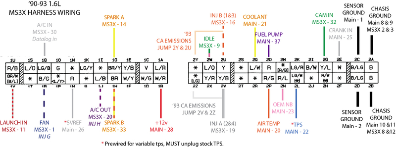
For fellow Newbies, I Used DIY BOB with their connectors - wired up mostly the way Brain showed in his first post. the DIY plugs/cable are very close to the pinout shown - an example of differences is that DIY has ground wires in Main 7, 8, 9, 17, 18 & 19. Pinout shows ground connected to 10 & 11, but there were no wires installed on the plug at 10 & 11.
JB & Matt both said it wouldn't make any difference, use one of the other grounds. I couldn't get a warm fuzzy about why this would work until I looked at a naked MS mother board. Seems All pins (except 3-6) across the 1 - 19 row are common ground. Sheez - why did'nt just say so?
Anyhow, its in the car finally, and we have some progress - unit powers up, throttle, AFR, MAP etc respond but we have no lift off yet. Calling it a day but at least we made PROGRESS!
Last edited by Team DNR; 11-26-2013 at 05:19 PM. Reason: Progress on Project
Reply
0
0

Thread
Thread Starter
Forum
Replies
Last Post
elesjuan
Build Threads
9
11-14-2018 12:18 PM
Andifer
Miata parts for sale/trade
8
09-23-2015 05:43 PM


