MEGAsquirt A place to collectively sort out this megasquirt gizmo

Idle VE Table Values?

Thread Tools
 
Search this Thread
 
Old 06-22-2018, 01:45 PM
  #61  
Junior Member
Thread Starter
 
JaveStack's Avatar
 
Join Date: May 2018
Location: Wisconsin
Posts: 57
Total Cats: 0
Default

One other thing Braineack, I am using your 1K resistor jumper method to try and maintain my tachometer function, but it isn't working. Is there something I am missing other than just jumping IG to B+ in the diagnostic port?
JaveStack is offline  
Old 06-22-2018, 02:38 PM
  #62  
Boost Czar
iTrader: (62)
 
Braineack's Avatar
 
Join Date: May 2005
Location: Chantilly, VA
Posts: 79,493
Total Cats: 4,080
Default

are you coil connectors 3 pin or 4?
Braineack is offline  
Old 06-22-2018, 02:53 PM
  #63  
Tweaking Enginerd
iTrader: (2)
 
Ted75zcar's Avatar
 
Join Date: Mar 2013
Location: Boulder, CO
Posts: 1,773
Total Cats: 354
Default

Originally Posted by JaveStack
i'm a little bit worried that this wont be a 1 to 1 comparison. Due to the firmware change between the diy version and mine, i got about 45 errors. I think I translated them all, but some do not translate directly between tunes. I'll translate as best I can between them and try it.
revert the firmware? Check the release notes from the version you used to the version on the MS?
Ted75zcar is offline  
Old 06-22-2018, 03:09 PM
  #64  
Junior Member
Thread Starter
 
JaveStack's Avatar
 
Join Date: May 2018
Location: Wisconsin
Posts: 57
Total Cats: 0
Default

Originally Posted by Braineack
are you coil connectors 3 pin or 4?
I'll check this afternoon. My gut says they are 4. But google images says they look nearly identical... so I can't be completely certain.
JaveStack is offline  
Old 06-22-2018, 06:09 PM
  #65  
Junior Member
Thread Starter
 
JaveStack's Avatar
 
Join Date: May 2018
Location: Wisconsin
Posts: 57
Total Cats: 0
Default

Originally Posted by Braineack
are you coil connectors 3 pin or 4?
Brain, they are four pin.
JaveStack is offline  
Old 06-22-2018, 06:13 PM
  #66  
Junior Member
Thread Starter
 
JaveStack's Avatar
 
Join Date: May 2018
Location: Wisconsin
Posts: 57
Total Cats: 0
Default

Originally Posted by Ted75zcar
revert the firmware? Check the release notes from the version you used to the version on the MS?
I gave the transition a shot without reverting firmware.

Added injector size, selected AFR targeting, set my sensor calibrations, added my fan relay output, put it in closed loop idle, corrected my timing offset, and set my spark to normal. Otherwise it is all DIY basemap now. Car runs much rougher at idle (due to untimed injection?) but the car runs where it should and drives great. Seems one of the combinations of settings I had was no bueno. Thank you!
JaveStack is offline  
Old 06-22-2018, 10:11 PM
  #67  
Tweaking Enginerd
iTrader: (2)
 
Ted75zcar's Avatar
 
Join Date: Mar 2013
Location: Boulder, CO
Posts: 1,773
Total Cats: 354
Default

Cool, now get it tuned and running well. Then you can start adding other stuff back in. Try to only make 1 change at a time so you can catch it if it goes sideways.
Ted75zcar is offline  
Old 06-23-2018, 09:35 AM
  #68  
Junior Member
Thread Starter
 
JaveStack's Avatar
 
Join Date: May 2018
Location: Wisconsin
Posts: 57
Total Cats: 0
Default

Originally Posted by Ted75zcar
Cool, now get it tuned and running well. Then you can start adding other stuff back in. Try to only make 1 change at a time so you can catch it if it goes sideways.
That makes sense. Now I just need to wait for brain to reply about the tach and I'll be all set
JaveStack is offline  
Old 06-23-2018, 04:19 PM
  #69  
Boost Czar
iTrader: (62)
 
Braineack's Avatar
 
Join Date: May 2005
Location: Chantilly, VA
Posts: 79,493
Total Cats: 4,080
Default

If 4 pin then the coils are providing the tach aignal, the 1k on ig- is just a pull-up. Dunnoz
Braineack is offline  
Old 06-26-2018, 01:35 PM
  #70  
Junior Member
Thread Starter
 
JaveStack's Avatar
 
Join Date: May 2018
Location: Wisconsin
Posts: 57
Total Cats: 0
Default

Originally Posted by Braineack
If 4 pin then the coils are providing the tach aignal, the 1k on ig- is just a pull-up. Dunnoz
Well... I guess the only way to test the output is with a scope right? (Which again, I don't have...) I'll make sire all the wires have continuity in the right places, rule out everything except the signal.
JaveStack is offline  
Old 06-26-2018, 04:31 PM
  #71  
Junior Member
 
NASSEX's Avatar
 
Join Date: Sep 2017
Location: Baltimore; States
Posts: 190
Total Cats: -35
Default

Stevejack, were you ever able to get the VE Fuel table sorted out to look a bit more normal? If so, could you post how it looks now? I'm new to this also.
Thx. Hope it works out for you.
NASSEX is offline  
Old 06-26-2018, 04:44 PM
  #72  
Junior Member
Thread Starter
 
JaveStack's Avatar
 
Join Date: May 2018
Location: Wisconsin
Posts: 57
Total Cats: 0
Default

Originally Posted by NASSEX
Stevejack, were you ever able to get the VE Fuel table sorted out to look a bit more normal? If so, could you post how it looks now? I'm new to this also.
Thx. Hope it works out for you.
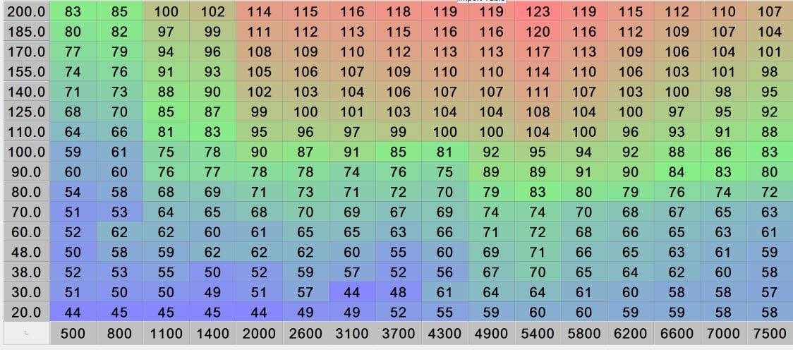
I was indeed. Loading the DIYAUTOTUNE base map (read: the entire tune) gave much better results, and after a few datalogs, the map hs changed only a little using VE Analyze. Looks like the below now. Please note my current maximum is 100kPa. I will not be running boost from my M45 until I sort out sequential injection and a knock sensor. So anything above 100 is currently untested and unverified to work well for me. Though the rest of the map has been pretty great and I dont expect many problems.

JaveStack is offline  
Old 06-26-2018, 05:08 PM
  #73  
Junior Member
 
NASSEX's Avatar
 
Join Date: Sep 2017
Location: Baltimore; States
Posts: 190
Total Cats: -35
Default

Sweet! Looks good thanks for the fast response
NASSEX is offline  
Old 06-28-2018, 09:05 AM
  #74  
Junior Member
Thread Starter
 
JaveStack's Avatar
 
Join Date: May 2018
Location: Wisconsin
Posts: 57
Total Cats: 0
Default

Received all my parts from Mouser and JBPERF for my 4 channel injector expansion board. Assembled it all Tuesday night, and it started first try yesterday! I have never soldered SMC before, so that was new and "exciting". I setup my injector order wrong at first, i wired everything 1-1-1. Realized my mistake after getting some unusual AFR readings last night, and changed it before I hit the hay. The injector channels are now hooked up in the firing order of the engine. INJ 1-1, INJ 2-3, INJ 3-4, INJ 4-2. Driving and datalogging on my way to work this morning, it all seems quite grand.

Still no Tach Function on dash.... makes me sad. Going to have to diagnose that next.
JaveStack is offline  
Old 07-14-2018, 11:48 AM
  #75  
Junior Member
Thread Starter
 
JaveStack's Avatar
 
Join Date: May 2018
Location: Wisconsin
Posts: 57
Total Cats: 0
Default no tach still

Okay, I still need some help with the tach.... I checked my grounds and my 12v supply to the tach. The needle quivers with the rest of the gauges when I key on. IG- on the diagnostic is confirmed continuous with the connector on the coil pack. Measuring frequency with my multimeter between IG- and ground gives me 100hz at idle. Using a 2k, 1k, or 470 ohm resistor from IG- to 12V gives no change in results on the dash.

At one point very early on, I had my tach signal wire jumped to my CAS. When I couldn't get the car to start I identified that as the issue and removed that jumper... Could that have killed my tach?
JaveStack is offline  
Old 07-16-2018, 10:58 AM
  #76  
Boost Czar
iTrader: (62)
 
Braineack's Avatar
 
Join Date: May 2005
Location: Chantilly, VA
Posts: 79,493
Total Cats: 4,080
Default

check ig- to ground. is it constant continuity?
Braineack is offline  
Old 07-16-2018, 11:35 AM
  #77  
Junior Member
Thread Starter
 
JaveStack's Avatar
 
Join Date: May 2018
Location: Wisconsin
Posts: 57
Total Cats: 0
Default

No continuity at idle. Diode test mode gives no beeps at idle. My MM is pretty cheap, it may not be able to keep up with the beeps in diode test mode. I get 60-100Hz in frequency test mode though?

I bit the bullet. I have a picoscope coming this week. It may waste everyone's time less if I just wait and post a screenshot of the output.

JaveStack is offline  
Old 07-16-2018, 12:36 PM
  #78  
Boost Czar
iTrader: (62)
 
Braineack's Avatar
 
Join Date: May 2005
Location: Chantilly, VA
Posts: 79,493
Total Cats: 4,080
Default

it should be the constant 12v (when jumped to b+ via a resistor) -- then when a coil is active, it grounds the tach singal. tach just measures the events per cycle, and viola engine speed.

ive seen bad coils keep ig- constantly grounded, and thus no tach.
Braineack is offline  
Old 08-20-2018, 09:41 PM
  #79  
Junior Member
Thread Starter
 
JaveStack's Avatar
 
Join Date: May 2018
Location: Wisconsin
Posts: 57
Total Cats: 0
Default

okay... so I got my scope, and finally stopped procrastinating about using it. Anyway, see attached. that is the unchanged signal (no pull up) coming off of my IG- wire. Thoughts? Is that normal looking?
Attached Thumbnails Idle VE Table Values?-scope-idle.png  

Last edited by JaveStack; 08-20-2018 at 09:52 PM.
JaveStack is offline  
Old 08-20-2018, 09:50 PM
  #80  
Junior Member
Thread Starter
 
JaveStack's Avatar
 
Join Date: May 2018
Location: Wisconsin
Posts: 57
Total Cats: 0
Default

When I jump IG- to 12V with a 1k resistor, the signal changes to the attached noise @ 1.3V, the 20V clipping light comes on, and the scope warns of overvoltage protection. Im thinking its getting transient spikes from the coil... Is that normal? Should i just swap coils for poops and chuckles to see what happens?
Attached Thumbnails Idle VE Table Values?-scope-idle-pullup-weird.png  
JaveStack is offline  


Quick Reply: Idle VE Table Values?


All times are GMT -4. The time now is 08:25 AM.