VTPS/Megasquirt Hardware mod help
 02-17-2009, 08:30 PM
#1
Elite Member
Thread Starter
iTrader: (9)

Join Date: Aug 2006
Location: Concord, North Carolina
Posts: 4,160
Total Cats: 6
Ok guys, I got the wells201 tps fitted and the wires soldered to the stock connector per Ben's thread.
EDIT:
I'm slightly confused on if I need to mod my board. I thought I did for a minute, MS1V3.
I have the TPS soldered as both Ben and Braineack has theirs, but my it wont calibrate, in MT it read 254 for both open/closed when I try to calibrate it. Any ideas?
EDIT:
I'm slightly confused on if I need to mod my board. I thought I did for a minute, MS1V3.
I have the TPS soldered as both Ben and Braineack has theirs, but my it wont calibrate, in MT it read 254 for both open/closed when I try to calibrate it. Any ideas?
Last edited by miatamania; 02-17-2009 at 10:09 PM.

Reply
 0
0

0
 02-17-2009, 10:07 PM
#4
Elite Member
Thread Starter
iTrader: (9)
Join Date: Aug 2006
Location: Concord, North Carolina
Posts: 4,160
Total Cats: 6
I'm not trying, but I keep reading that you needed to so that is what I wanted to get cleared up is if I need to. So I don't need to have any mods done to my v3 board.
TPS is NOT working in MT, its reading 254 off/on the throttle when trying to calibrate. So...no change from stock. ideas?
TPS is NOT working in MT, its reading 254 off/on the throttle when trying to calibrate. So...no change from stock. ideas?
Reply
0
0
02-17-2009, 10:17 PM
#5
Yes, I battled this for a couple hours a few weeks ago. I'll give you some ideas based on my mistakes.
First, I initially did not have both the blue TPS wire AND the +5 Vref wires spliced into the stock harness, I just had the blue one. Do you have them both plugged in? I think one goes to 1n and the other to 2L at the stock harness. My old thread has that in it for sure, i've forgotten by now.
Second, change one of your gauges in MT to the TPS ADC gauge, when that starts moving in a way that makes sense, then you can calibrate.
Also, are you standalone or parallel? Not sure if that would make a difference or not...
Reply
0
0
02-17-2009, 10:26 PM
#6
Elite Member
Thread Starter
iTrader: (9)
Join Date: Aug 2006
Location: Concord, North Carolina
Posts: 4,160
Total Cats: 6
parallel.
I thought you could leave the factory harness alone?
I didn't build the harness so I guess I need to check the wiring and figure out what is going on.
I thought you could leave the factory harness alone?
I didn't build the harness so I guess I need to check the wiring and figure out what is going on.
Reply
0
0
02-18-2009, 10:13 AM
#7
Boost Czar


iTrader: (62)
Join Date: May 2005
Location: Chantilly, VA
Posts: 79,490
Total Cats: 4,079
more than likely you have two wires you need to make homes for. a blue and a gray wire, verify they are somewhere coming out of your MS's db37 harness, and I'll help you find a home for them...
Reply
0
0
 02-20-2009, 10:10 AM
#12
Boost Czar
iTrader: (62)
Join Date: May 2005
Location: Chantilly, VA
Posts: 79,490
Total Cats: 4,079
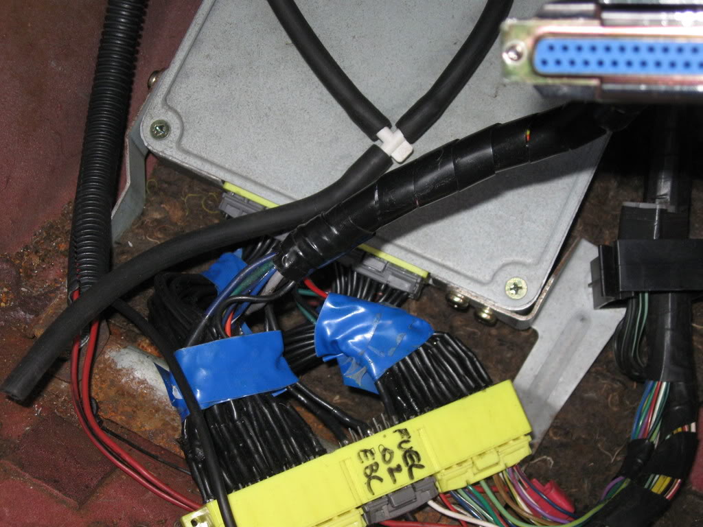
you're going to have to unwrap the wires and find the thin solid gray (labeled 5vref) and thin solid blue (labeled tps) wires that aren't hooked up to anything.
you're going to want to pull the harness out of the car anyway because you'll need to solder these to the yellow connector
you're going to want to pull the harness out of the car anyway because you'll need to solder these to the yellow connector
Reply
0
0
02-20-2009, 11:34 AM
#13
Elite Member
Thread Starter
iTrader: (9)
Join Date: Aug 2006
Location: Concord, North Carolina
Posts: 4,160
Total Cats: 6
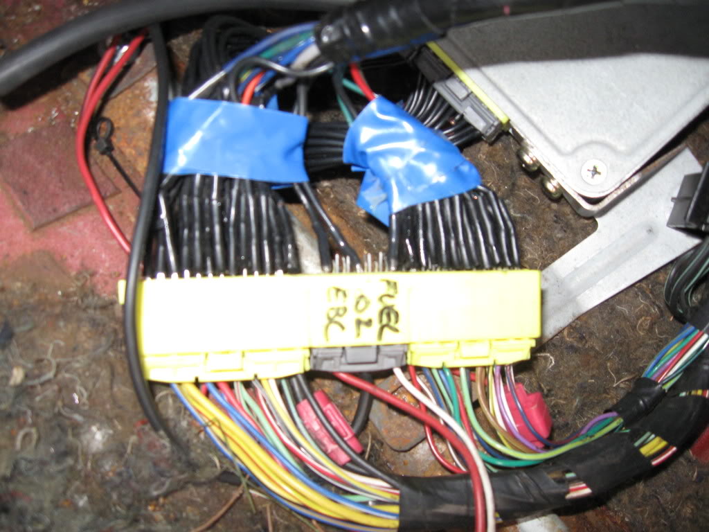
The yellow connector connects to the stock harness right? Do I need to solder it to the pins or to the wires? I can't see my pictures at school so I'm trying to do this from memory in my head.
Thanks...I'm slowly learning what I need to do/how to use this thing.
Thanks...I'm slowly learning what I need to do/how to use this thing.
Reply
0
0
02-20-2009, 12:05 PM
#14
Boost Czar
iTrader: (62)
Join Date: May 2005
Location: Chantilly, VA
Posts: 79,490
Total Cats: 4,079
on the db37 connector to the MS, there are two wires that should (sometimes I leave them out) be soldered in positions 22 and 26:

These are NOT attached to the yellow 64 pin connector on the boomslang harness.
You need to run the gray wire (5vref) to position 1N on the boomslang connector and the blue wire (TPS) to position 2L.
http://boostedmiata.com/MS/db37_MS_pinouts.jpg
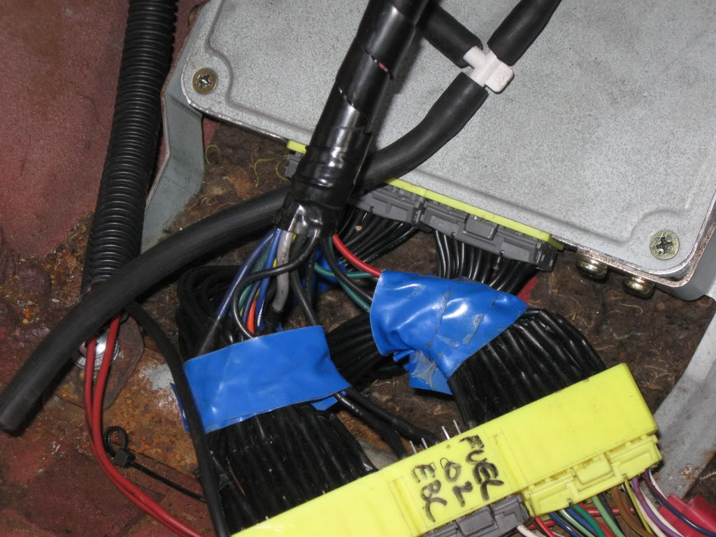
You then need to cut the black wires leading back to the stock ECU on each of those (like the 4 wire over on your first picture, notice it's cut). Then you should be good to go.
These are NOT attached to the yellow 64 pin connector on the boomslang harness.
You need to run the gray wire (5vref) to position 1N on the boomslang connector and the blue wire (TPS) to position 2L.
http://boostedmiata.com/MS/db37_MS_pinouts.jpg
You then need to cut the black wires leading back to the stock ECU on each of those (like the 4 wire over on your first picture, notice it's cut). Then you should be good to go.
Reply
0
0
02-20-2009, 01:50 PM
#15
Elite Member
Thread Starter
iTrader: (9)
Join Date: Aug 2006
Location: Concord, North Carolina
Posts: 4,160
Total Cats: 6
Gotcha, I thought that is what you meant, just wanted to clear it up. Not being able to see pictures confused me. I guess it just blocks free/open websites, because I can see your pinout just fine.
Thanks a lot, I'll do this in a couple of hours and see if it works.
Thanks a lot, I'll do this in a couple of hours and see if it works.
Reply
0
0
02-20-2009, 09:12 PM
#16
Elite Member
Thread Starter
iTrader: (9)
Join Date: Aug 2006
Location: Concord, North Carolina
Posts: 4,160
Total Cats: 6
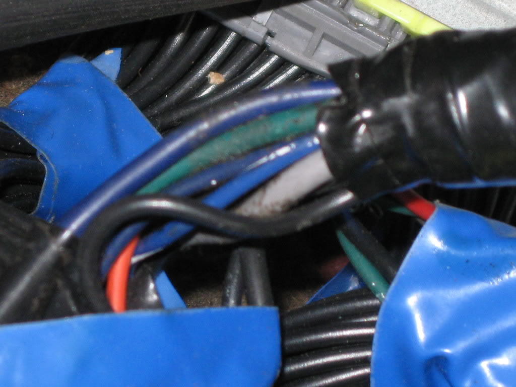
The grey wire isn't running to anything, it is just chilling out. So that looks simple enough.
There is a blue TPS sig wire that is running spliced into a wire that looks like it goes to 2M on the boomslang and 2M the grey connector.
Should I just cut both wires. (the 2M - 2M) and just wire the blue straight to 2L and cut the 2L to 2L?
There is a blue TPS sig wire that is running spliced into a wire that looks like it goes to 2M on the boomslang and 2M the grey connector.
Should I just cut both wires. (the 2M - 2M) and just wire the blue straight to 2L and cut the 2L to 2L?
Reply
0
0


