I cannot control Idle, tune & log attached.
 03-29-2014, 03:05 PM
#1
Elite Member
Thread Starter
iTrader: (6)

Join Date: Feb 2013
Location: A cave in Va
Posts: 3,395
Total Cats: 456
CurrentTune.msq
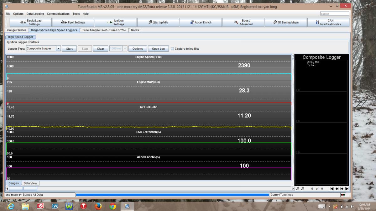
I cannot make my car idle any lower than 2k. I have adjusted fuel and timing in large and small amounts with no big difference except in afr reading. I'm sure I have a few settings that are incorrect. AFR gauge and tunerstudio match. Attached is my current tune. Anyone interested I helping out a bit?
1995 1.8
WB MTX L
Header, 2-1/4" from header out,high flow cat
ghetto cold air
exhintake
Running in open loop currently
Last edited by ryansmoneypit; 04-06-2014 at 09:58 PM.

Reply
 -1
-1

-1
 03-29-2014, 08:17 PM
#3
Elite Member
Thread Starter
iTrader: (6)
Join Date: Feb 2013
Location: A cave in Va
Posts: 3,395
Total Cats: 456
hi idle.csv
Here is a short log. I notice that I am getting an incorrect air temp. it says 68 deg. no matter what. I'm not too surprised, directions are somewhat conflicting on tapping into the maf wires. DIY says that I should have a yellow wire and a brown one, or something like that. then I found another write up saying black with red stripe and a ground. this looked like mine so I went with it. both directions had the connection in the same location though..
Here is a short log. I notice that I am getting an incorrect air temp. it says 68 deg. no matter what. I'm not too surprised, directions are somewhat conflicting on tapping into the maf wires. DIY says that I should have a yellow wire and a brown one, or something like that. then I found another write up saying black with red stripe and a ground. this looked like mine so I went with it. both directions had the connection in the same location though..
Reply
0
0
03-30-2014, 02:06 PM
#5
Elite Member
Thread Starter
iTrader: (6)
Join Date: Feb 2013
Location: A cave in Va
Posts: 3,395
Total Cats: 456

Still idling at 2K.
Still not sure why I am not getting an AIT reading. This one seems to be a default, considering that it was 45 deg F. when I took this sample.
-Tuner Noob
Edit- IAT tested bad, purchased a new one and it tested good. plugged it in, no real IAT reading that I believe. re tested and it is bad now. I wired into the maf per the megamanual instructions but something is definitely wrong. The larger red and black wires are the ones I spliced in.
Last edited by ryansmoneypit; 03-31-2014 at 05:45 PM.
Reply
0
0
 03-31-2014, 06:34 PM
#7
Elite Member
Thread Starter
iTrader: (6)
Join Date: Feb 2013
Location: A cave in Va
Posts: 3,395
Total Cats: 456
Read the mega manual, figure out that some of it doesnt apply to the newest tunerstudio, Sift through 100's of threads and spend a few weekends banging your forehead against a keyboard. That's the route I'm taking.
Reply
0
0
03-31-2014, 09:49 PM
#9
Elite Member
Thread Starter
iTrader: (6)
Join Date: Feb 2013
Location: A cave in Va
Posts: 3,395
Total Cats: 456
Ok I can accept that none of the really good guys around here have any interest in another idle issue, especially since I have not made a good impression in the past. what I would really appreciate though, is for someone to look at my IAT wiring and at least help me figure out why I am burning out new sensors instantly.
Thanks
Thanks
Reply
0
0

 04-04-2014, 08:17 AM
#12
Elite Member
Thread Starter
iTrader: (6)
Join Date: Feb 2013
Location: A cave in Va
Posts: 3,395
Total Cats: 456
I tested the resistance at room temp and get something like 3.5 k or something. Then after I plug it in and run the car, if I test it again I just get an OL. signal. Maybe this isn't the correct way to test? Either way, I never get an actual air temp. Is it my version of tuner studio? The only gauge I have says est. Air temp. What the F does that mean? Why is it an estimation and not actual? Right now the actual air temp IS the same as the estimated air temp, so at least I get to fiddle around with it.
Reply
0
0
 04-04-2014, 03:28 PM
#14
The IAT replaces that entire part of the system. It should be wired like this.
DIYPNP MegaSquirt installation for the Mazda Miata (scroll down to "Deleting the MAF")
If I'm seeing this correctly, you have two sensors conflicting on the same circuit.
Reply
0
0
04-04-2014, 03:36 PM
#15
Elite Member
Thread Starter
iTrader: (6)
Join Date: Feb 2013
Location: A cave in Va
Posts: 3,395
Total Cats: 456
No. The Maf is gone. Just instead of shoving wires into the plug, I soldered them into the wires on the back side. I have looked at that instruction many times. Like I said, they say to connect to wire colors that I do not have. So I just used the same locations. 3&4 I believe.
Reply
0
0
04-04-2014, 03:40 PM
#16
Elite Member
Thread Starter
iTrader: (6)
Join Date: Feb 2013
Location: A cave in Va
Posts: 3,395
Total Cats: 456
Well the wire is brand new and only 12" long before it goes to the factory harness for that maf. Not sure what I would be looking for as far as continuity. One should be ground and the other should be what? I'm assuming you are talking about the factory harness?
Reply
0
0
04-04-2014, 03:40 PM
#17
I would recommend pinning them out to ensure that "3 & 4" are in fact the sensor wires, especially if the colors are not what you expected to find.
General "good engineering practice" is to never assume that because a wire is in the correct location at one end, that it is in the correct location at the other.
The fact that the readings are wrong, and the sensors are failing tells me the sensor is wired wrong.
General "good engineering practice" is to never assume that because a wire is in the correct location at one end, that it is in the correct location at the other.
The fact that the readings are wrong, and the sensors are failing tells me the sensor is wired wrong.
Reply
0
0
04-04-2014, 03:44 PM
#20
What is continuity?
You might be asking, "What is continuity?" But don't worry, it's quite simple! Continuity means, are two things electrically connected. So if two electronic parts are connected with a wire, they are continuous. If they are connected with cotton string, they are not: while they are connected, the cotton string is not conductive.
You can always use a resistance-tester (ohmmeter) to figure out if something is connected because the resistance of wires is very small, less than 100 ohms, usually. However, continuity testers usually have a piezo buzzer which beeps. This makes them very useful when you want to poke at a circuit and need to focus on where the probes are instead of staring at the meter display.
For some basic circuits you can just look to see where the wires go to determine continuity but it's always wise to use a multimeter. Sometimes wires break or you're tired and can't easily follow all the PCB traces. I use continuity check all the time!
What is it good for?
Continuity is one of the most important tests. Here are some things it is good for
Determine if your soldering is good. If your solder joint it is a cold solder connection it will appear connected but in actually it is not! This can be really frustrating if you are not experienced in visually detecting cold solder joints
Determine if a wire is broken in the middle. Power cords and headphone cables are notorious for breaking inside the shielding, it appears as if the cable is fine but inside the wires have been bent so much they eventually broke.
Making sure something isn't connected. Sometimes a solder joint will short two connections. Or maybe your PCB has mistakes on it and some traces were shorted by accident.
Reverse-engineering or verifying a design back to a schematic
Remember!
You can only test continuity when the device you're testing is not powered. Continuity works by poking a little voltage into the circuit and seeing how much current flows, its perfectly safe for your device but if its powered there is already voltage in the circuit, and you will get incorrect readings
Always test to make sure your meter is working before starting the test by brushing the two tips together, and verifying you hear the beep. Maybe the battery is low or its not in the right mode.
Continuity is non-directional, you can switch probes and it will be the same.
If you are testing two points in a circuit and there is a (big) capacitor between those points you may hear a quick beep and then quiet. That's because the voltage the meter is applying to the circuit is charging up the capacitor and during that time the meter 'thinks' its continuous (essentially)
Small resistors (under 100 ohms or so) and also all inductors will seem like short circuits to a multimeter because they are very much like wires.
Likewise, continuity doesn't mean "short" it just means very very low resistance. For example, if you have a circuit that draws an Amp from a 5V supply, it will appear to be a 5Ω resistor. If you measure that with your meter it will think its a short circuit, but really its just a high-drain circuit.
Reply
0
0


