MS1 v3.0 questions
 12-14-2012, 08:27 PM
#1
Junior Member
Thread Starter
iTrader: (6)

Join Date: Nov 2010
Location: Three Rivers, Ca
Posts: 176
Total Cats: 4
Yesterday I received my first Megasquirt and I’m really excited to get this thing up and running but I have a few newbish questions concerning rewiring the harness and the mods that exist on the board. Unfortunately I haven't had to look at a wiring diagram since high school (we won't discuss how long ago that was) but at least I can still solder.
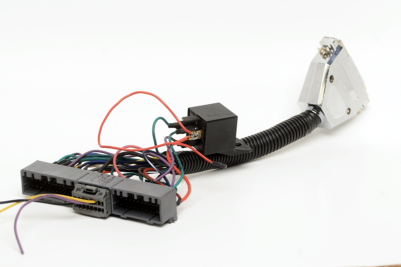
First, a bit of background on this unit…the original owner had Scott build him this MS a couple years ago for his ’95 with A/C, cruise control and IAT, and that’s about all he could remember, I guess. He never used it and the fella who bought it from him rewired it to work with his ’96 turbo. I bought it from this guy and now I have to rewire the harness to run it as a standalone in my stock ’91 1.6 with an MTX-L wideband and no AFM.
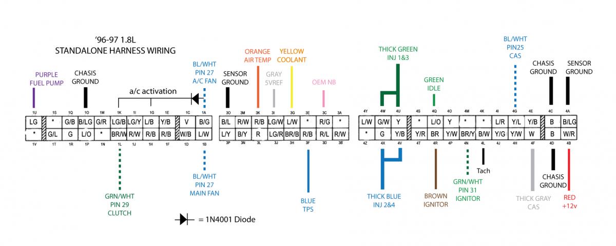
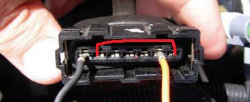
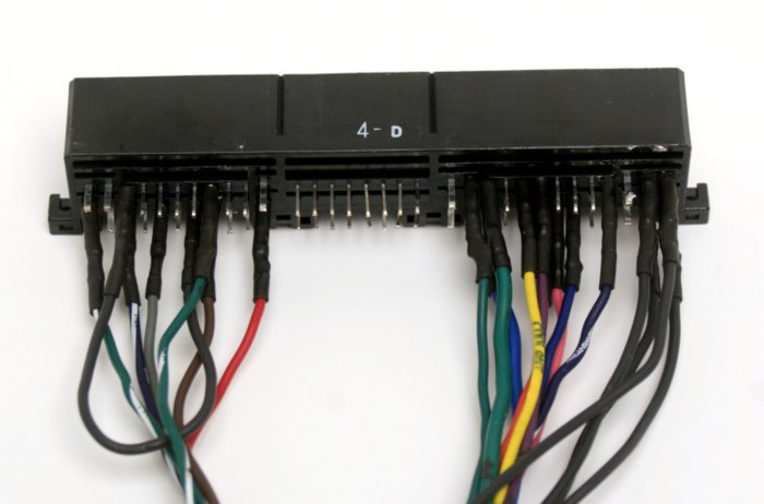
So, I’ve been studying the thread on how to make and install your diy Megasquirt and I noticed that the ground wires are supposed to be soldered and bridged to pins 7,8,9 and 17,18,19 on the DB37 connector, but on my DB37 the ground wires are soldered to 7,8,9 and then to 12,13,14 as in the photo below:
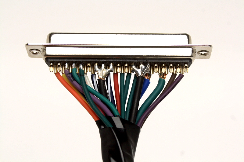
I'm not sure why this is and am a bit confused over it. The DIYautotune site says these pins are connected to the ground plane also, so do I leave the DB37 connector as is or move 12-14 over to 17-19 and bridge them as per Scott’s writeup?
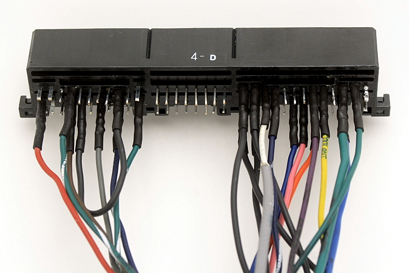
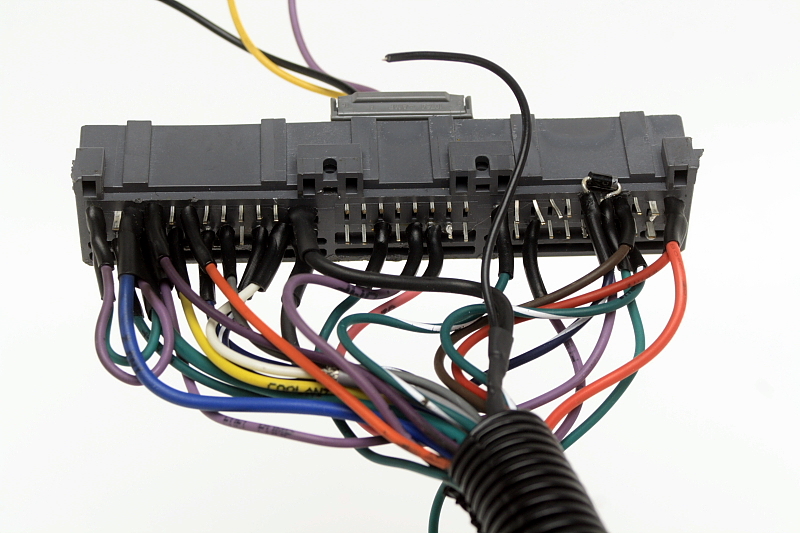
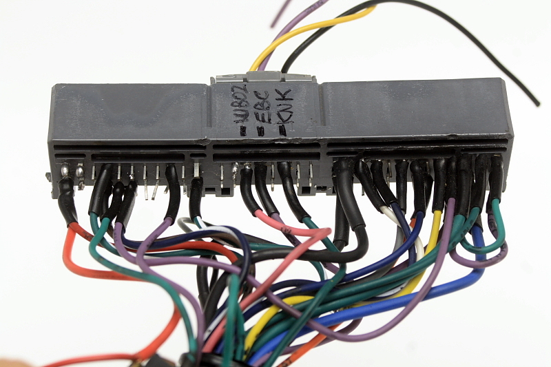
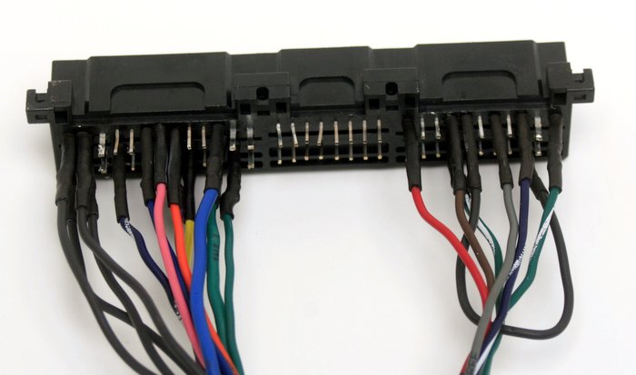
Next, here are photos of the 64-pin connector as it sits now. It doesn't look anything like what I saw on Scott's writeup for a '96 but I suppose this is irrelevant for my purposes and I just need to resolder the wires to the appropriate pins for my '91? Unless anything's changed since that writeup?
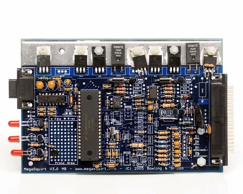
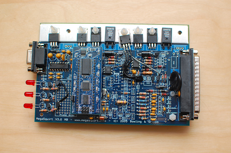
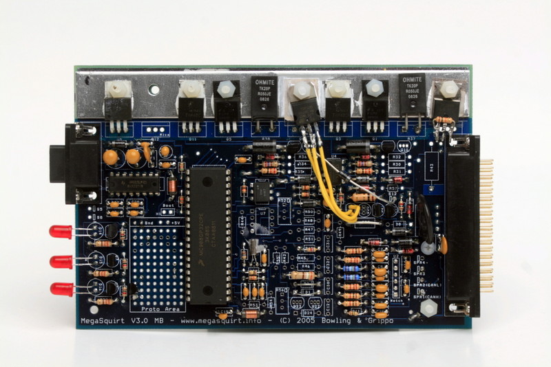
I'll include pics of the MS board as well in case anyone might need to look at it to help answer my questions or inform me of any other mods on this unit.
I'm sure I'll have many other questions but thanks if you can help with these!
Ray
First, a bit of background on this unit…the original owner had Scott build him this MS a couple years ago for his ’95 with A/C, cruise control and IAT, and that’s about all he could remember, I guess. He never used it and the fella who bought it from him rewired it to work with his ’96 turbo. I bought it from this guy and now I have to rewire the harness to run it as a standalone in my stock ’91 1.6 with an MTX-L wideband and no AFM.
So, I’ve been studying the thread on how to make and install your diy Megasquirt and I noticed that the ground wires are supposed to be soldered and bridged to pins 7,8,9 and 17,18,19 on the DB37 connector, but on my DB37 the ground wires are soldered to 7,8,9 and then to 12,13,14 as in the photo below:
I'm not sure why this is and am a bit confused over it. The DIYautotune site says these pins are connected to the ground plane also, so do I leave the DB37 connector as is or move 12-14 over to 17-19 and bridge them as per Scott’s writeup?
Next, here are photos of the 64-pin connector as it sits now. It doesn't look anything like what I saw on Scott's writeup for a '96 but I suppose this is irrelevant for my purposes and I just need to resolder the wires to the appropriate pins for my '91? Unless anything's changed since that writeup?
I'll include pics of the MS board as well in case anyone might need to look at it to help answer my questions or inform me of any other mods on this unit.
I'm sure I'll have many other questions but thanks if you can help with these!
Ray
Last edited by RayinNorCal; 12-14-2012 at 09:13 PM.

Reply
 0
0

0
12-15-2012, 09:03 AM
#2
Boost Czar


iTrader: (62)
Join Date: May 2005
Location: Chantilly, VA
Posts: 79,493
Total Cats: 4,080
is this that $50 one where that guy was under-handingly trying to say i built it wrong and he had the "fix" it?
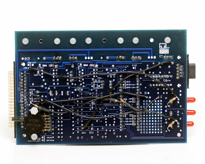
looks like they removed the tachout from js2, idle control, FAN control, and boost control from it. the bottom of the board looks untouched from my wiring.
I'd remove the relay.
That gray connector was from a part number that's absolutely the worst to solder to. When you redo the harness, make sure all your joints are secure, the solder isn't going to want to hold to the pins. Then I'd coat it all in hot glue so they dont work there way loose/break.
dont run anything to 1C, instead, run the FP wire on pin 37 to 2O, you can then use a jumper wire in the AFM connector to complete the circuit back to the fuel pump relay.
Reply
0
0
12-15-2012, 12:32 PM
#3
Junior Member
Thread Starter
iTrader: (6)
Join Date: Nov 2010
Location: Three Rivers, Ca
Posts: 176
Total Cats: 4
Thanks Scott. That helps a lot but I'm now thinking I may as well go with a parallel harness. If you have some time next month how much would you charge to build me one? Given my lack of involvement in electronics over the years I'd actually feel much better having someone else build it for me.
And yes, this is that same you unit you referred to but the seller wasn't speaking of you in his for sale thread. What happened was that he bought it from Ken who had you build it for his '95. Ken never used it and sold it to Paul who thought he could just plug it in to his '96 but of course it wouldn't work. So he and a friend rewired it as shown in my pics above. Did he post somewhere else claiming you screwed up?
Ray
Reply
0
0
 01-02-2013, 11:15 AM
#6
Junior Member
Thread Starter
iTrader: (6)
Join Date: Nov 2010
Location: Three Rivers, Ca
Posts: 176
Total Cats: 4
Ok, so I got off my lazy duff and ordered a new 64-pin connector from DIYautotune so I could start working on my standalone harness. Once I received it I quickly realized my soldering skills could use some work but I think they will suffice. Now, I’m almost done with the harness but I have a few questions.
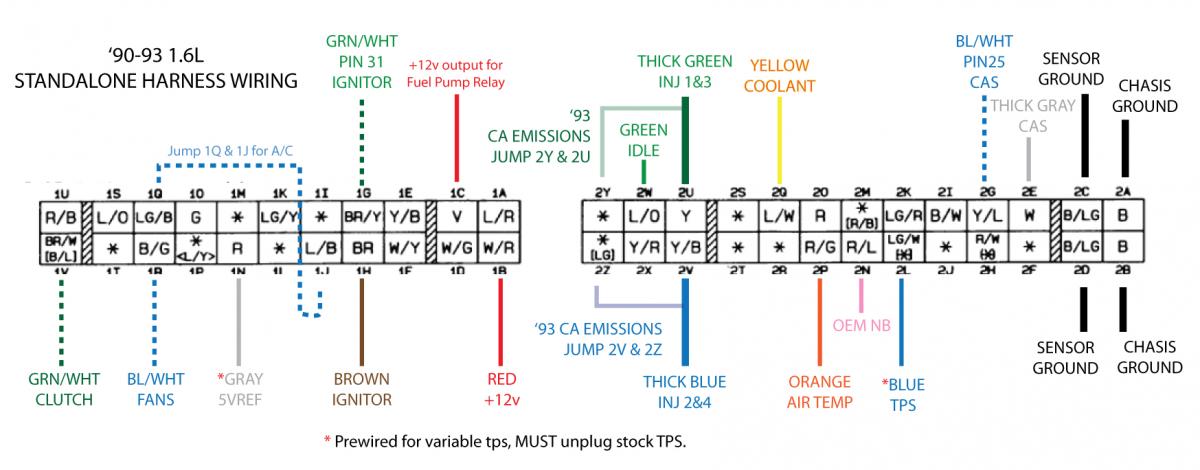
First, I cross-referenced Joe’s writeup here and used the Green wire from pin 30 to connect to 2W for idle. Just want to make sure this is correct.
Second, regarding the two black ground wires coming off the db37: I imagine it doesn’t matter which of the two wires goes to either the sensor or ground pins on the 64-pin connector, but I’m assuming I must split one of the wires and connect each end to 2C/2D respectively and then split the other wire for 2A/2B?
Third, I haven't looked at the AFM wiring yet but where do I connect the jumper wire to complete the circuit back to the fuel pump relay? I have connected the fuel pump wire to 2O on the MS harness.
I’ll post a pic of the harness once I finish connecting the ground wires in case anyone would like to look it over to see if there are any problems with it.
Ray
Reply
0
0
01-02-2013, 11:25 AM
#7
Boost Czar
iTrader: (62)
Join Date: May 2005
Location: Chantilly, VA
Posts: 79,493
Total Cats: 4,080
First, I cross-referenced Joe’s writeup here and used the Green wire from pin 30 to connect to 2W for idle. Just want to make sure this is correct.
Second, regarding the two black ground wires coming off the db37: I imagine it doesn’t matter which of the two wires goes to either the sensor or ground pins on the 64-pin connector, but I’m assuming I must split one of the wires and connect each end to 2C/2D respectively and then split the other wire for 2A/2B?
Third, I haven't looked at the AFM wiring yet but where do I connect the jumper wire to complete the circuit back to the fuel pump relay? I have connected the fuel pump wire to 2O on the MS harness.
the black and orange are the AIT sensor positions. the red line is jumping 2O back to the Fuel Pump Relay.
I’ll post a pic of the harness once I finish connecting the ground wires in case anyone would like to look it over to see if there are any problems with it.

Reply
0
0
01-02-2013, 08:52 PM
#9
Junior Member
Thread Starter
iTrader: (6)
Join Date: Nov 2010
Location: Three Rivers, Ca
Posts: 176
Total Cats: 4
I connect pin 1 to 2C, pin 2 to 2D, pin 8 to 2A, and pin 9 to 2B...
...the black and orange are the AIT sensor positions. the red line is jumping 2O back to the Fuel Pump Relay.
...the black and orange are the AIT sensor positions. the red line is jumping 2O back to the Fuel Pump Relay.
inspiration
Ray
Reply
0
0
01-03-2013, 08:07 AM
#10
Boost Czar
iTrader: (62)
Join Date: May 2005
Location: Chantilly, VA
Posts: 79,493
Total Cats: 4,080
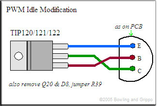
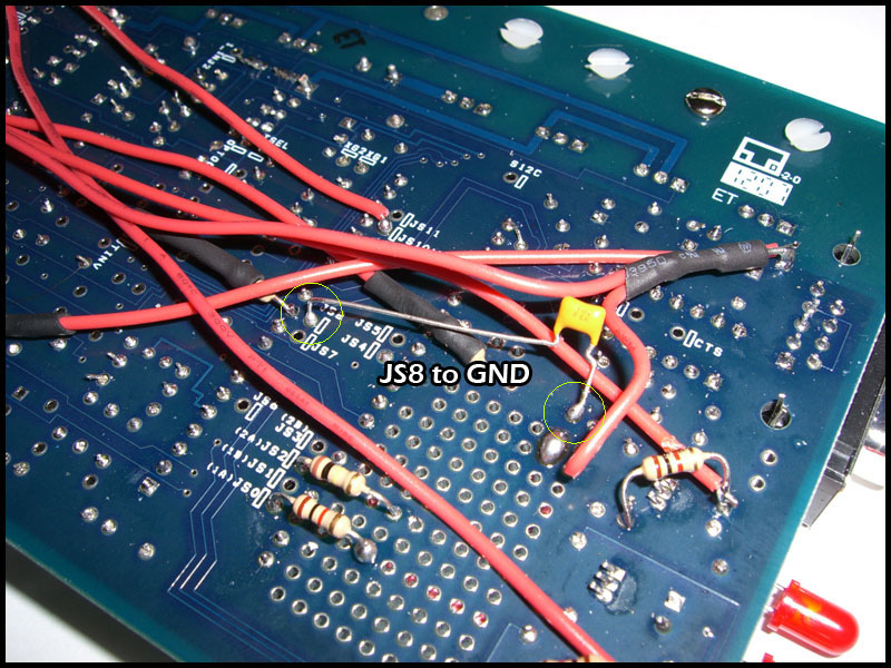
you should also run a diode from the middle pin back to s12:
Should I do likewise for the fan control that was removed?
----
One more thing, I'd probably add a simple relay cirucit on the proto board so you could input your a/c into the MS and out through the the relay and use the gslender code so you have improved idle functions and a/c feed forward.
Reply
0
0
01-03-2013, 11:04 AM
#11
Junior Member
Thread Starter
iTrader: (6)
Join Date: Nov 2010
Location: Three Rivers, Ca
Posts: 176
Total Cats: 4
Thanks again for the help, Scott.
I'm beginning to see why this was a $50 Megasquirt, lol. Not that I mind working on it as its kinda fun and geeky, I just wish I knew more about electronics gadgetry. I'll attempt those fixes once I get a chance to head down the hill into town to get a new soldering iron. The old one went kaput last night.
Ray
Reply
0
0
01-05-2013, 12:13 AM
#13
Junior Member
Thread Starter
iTrader: (6)
Join Date: Nov 2010
Location: Three Rivers, Ca
Posts: 176
Total Cats: 4
So, I just finished my first harness, I hope. Told you it wouldn't be pretty. I tried to follow the diagram exactly plus your notes but I could have easily goofed up somewhere--or everywhere.
To show you what an amateur I am, on almost every wire I kept forgetting to put the heat shrink on first before soldering to the connector, torched the cord on my old soldering gun and broke the screw that holds in the tip, pretty much ruined a small dish that served as a resting place for the soldering iron, and even managed to burn my wife on the arm once. Good times.
So anyway, here's some photos:
Ray
Reply
0
0
01-05-2013, 01:56 PM
#14
Boost Czar
iTrader: (62)
Join Date: May 2005
Location: Chantilly, VA
Posts: 79,493
Total Cats: 4,080
looks good actually. eventually you should upgrade the a/c switch wiring and use feed forward firmware.
there's just one issue, and I hate to tell you this...
you completely populated it backwards. The black grounds end up on the inside of the harness, the red power on the outside. The diagram pictured is show as looking into the plugs, not from the backside...


Take notice how mine is wired in the pic I posted compared to yours...
there's just one issue, and I hate to tell you this...
you completely populated it backwards. The black grounds end up on the inside of the harness, the red power on the outside. The diagram pictured is show as looking into the plugs, not from the backside...
Take notice how mine is wired in the pic I posted compared to yours...
Reply
0
0
01-05-2013, 03:18 PM
#15
Junior Member
Thread Starter
iTrader: (6)
Join Date: Nov 2010
Location: Three Rivers, Ca
Posts: 176
Total Cats: 4
looks good actually. eventually you should upgrade the a/c switch wiring and use feed forward firmware.
there's just one issue, and I hate to tell you this...
you completely populated it backwards. The black grounds end up on the inside of the harness, the red power on the outside. The diagram pictured is show as looking into the plugs, not from the backside...
Take notice how mine is wired in the pic I posted compared to yours...
Reply
0
0
01-09-2013, 03:03 AM
#16
Junior Member
Thread Starter
iTrader: (6)
Join Date: Nov 2010
Location: Three Rivers, Ca
Posts: 176
Total Cats: 4
My harness will be on hold for a few days but I did make a little progress on the board itself.
First, tip120 is reinstalled with a diode to S12. Mutt ugly soldering but it will hold. Also, the resistor is back in place on R27. I looked on the back of the board and it appears there already is a wire going from the LED to IAC1B (see pic in first post). So, hopefully I've got idle and fan control back under control.
You said: "looks like they removed the tachout from js2."
Yes, and looking at my board a bit closer it appears they removed JS0 as well. Question: I can't quite tell from your photo but what resistor does JS2 take? And I assume I should replace JS0 too. Looks like a 1K resistor? Hard for me to tell.
Ray
Reply
0
0