‘96-97 DIYPNP Jumper Visual Map
 03-27-2014, 12:36 PM
#1
Newb
Thread Starter

Join Date: Mar 2014
Location: Boston
Posts: 13
Total Cats: 4
Hello all, I am in the process of finishing up a DIYPNP build and just started on the wiring connecting the main board to the connector board. So, I figured that I would post some pictures mapping these connections visually as I go along. I know this should be very straight forward to most, but I am doing this for two reasons. One, because if you are like me, having a visual map makes following this wiring a thousand times easier than following written instructions alone. Two, I am also adding this here so people with more DIYPNP build experience can hopefully “check my work” to make sure that I am indeed connecting the 2 boards correctly, and if not, how to correct any mistakes that I may have made, and mary the boards correctly.
Also, the wiring below follows the path outlined here and my car is of the same specs listed:
DIYPNP MegaSquirt installation for the Mazda Miata
*Note: I may go a different route with the A/C hook up that I’ve read about that does not require the removal of the R14 resistor. I will cross this bridge as I move along.
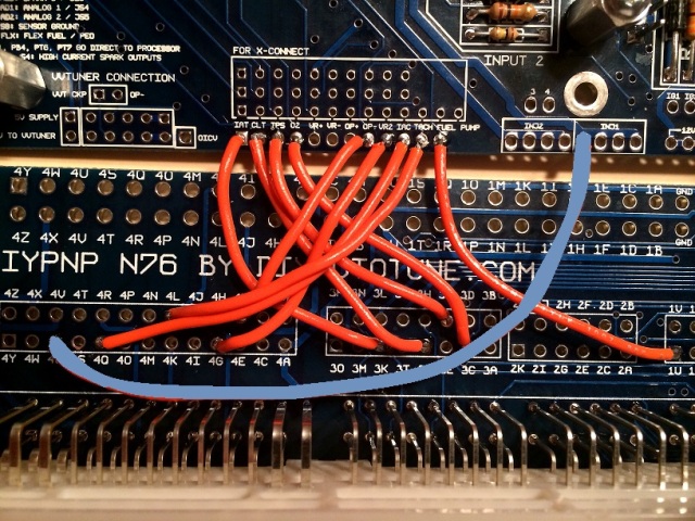
So here we go. (I have only made 10 connections so far but will add more ASAP)
IAT to 3K
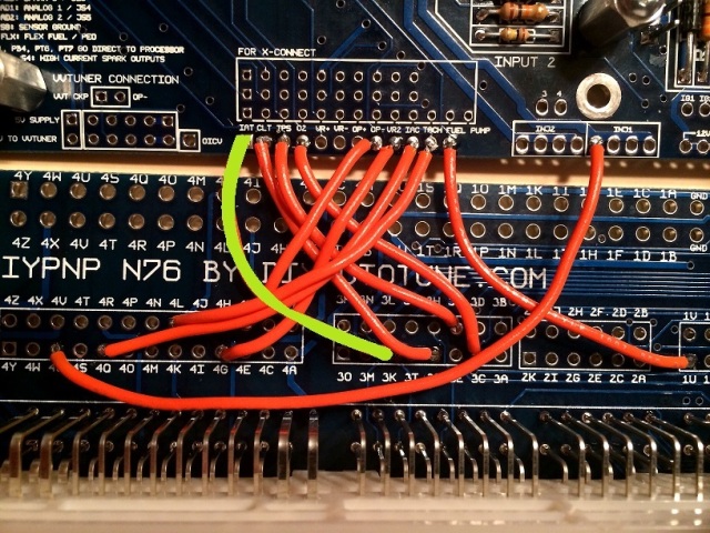
CLT to 3G
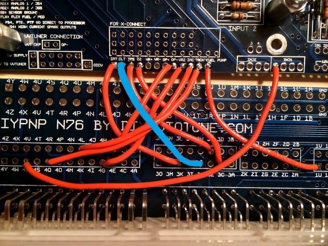
TPS to 3F
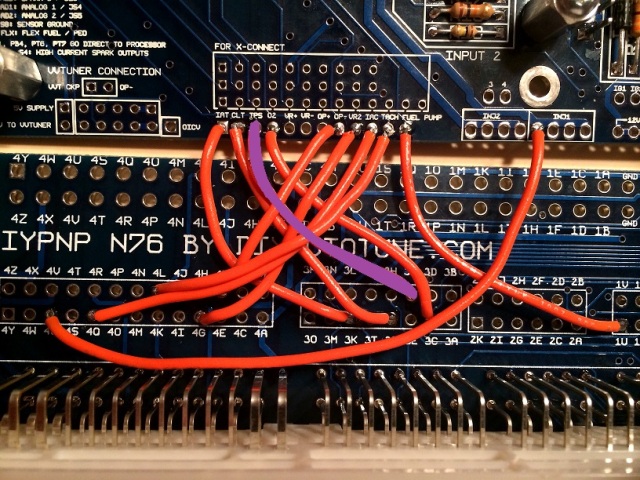
O2 to 3C
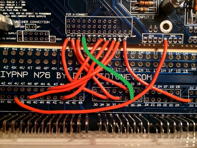
OP- to 4F
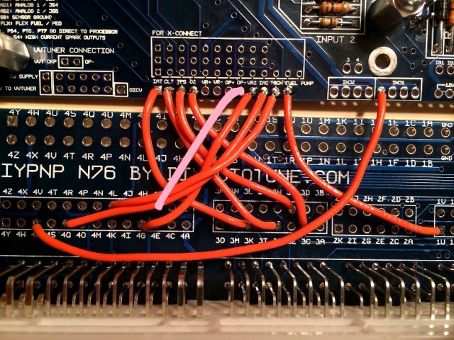
VR2 to 4G
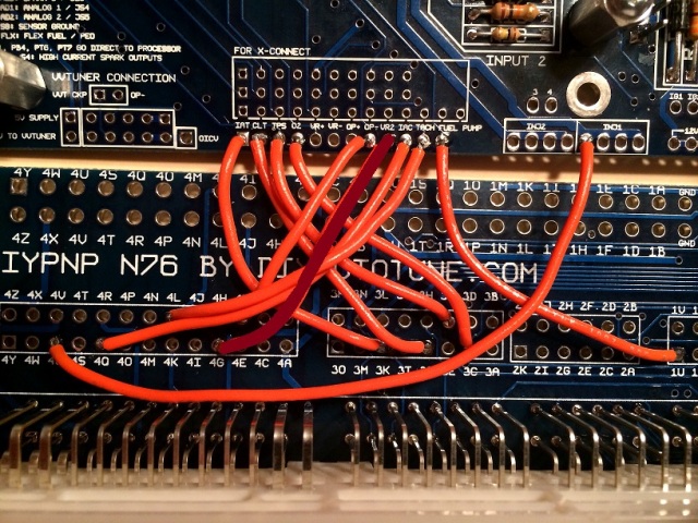
IAC to 4Q
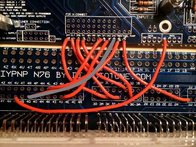
TACH to 4L
FUEL to 1U
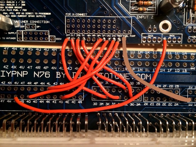
INJ1 to 4U
Also, the wiring below follows the path outlined here and my car is of the same specs listed:
DIYPNP MegaSquirt installation for the Mazda Miata
*Note: I may go a different route with the A/C hook up that I’ve read about that does not require the removal of the R14 resistor. I will cross this bridge as I move along.
So here we go. (I have only made 10 connections so far but will add more ASAP)
IAT to 3K
CLT to 3G
TPS to 3F
O2 to 3C
OP- to 4F
VR2 to 4G
IAC to 4Q
TACH to 4L
FUEL to 1U
INJ1 to 4U

Reply
 1
1

1

 03-28-2014, 09:24 AM
#3
Newb
Thread Starter
Join Date: Mar 2014
Location: Boston
Posts: 13
Total Cats: 4
But if you find this useless have the thread deleted. Fine by me.

Reply
1
1
03-31-2014, 11:19 AM
#4
Junior Member

Join Date: Nov 2010
Location: London, UK
Posts: 102
Total Cats: 0
For ref I'm running DIYPNP on a 96-97 Eunos.
Whilst I haven't done it quite to the level you have, I do get where you're coming from....I capture extra info in Excel if I think it'll be usefil, listi out the connections I made, then checked, etc. Including noting down ECU factory pinout purposes and misc plugs uses as I found them in the factory loom diagrams and on here/the web. For me it helped when I needed to change setup from 94 to 96 ECU pinouts, plus a few other changes in between as I configure the custom outputs, switched basemaps to use A/C idle up (recommended on here) and finally now ditching A/C.
Anyway more importantly, the wires you've shown there are fine. What variations/extras from the 'standard' diyautotune setup are you planning on running?
-Seq Injection module?
-A/C?
-Boost control/Table switching etc?
Reply
0
0
03-31-2014, 12:22 PM
#5
Newb
Thread Starter
Join Date: Mar 2014
Location: Boston
Posts: 13
Total Cats: 4
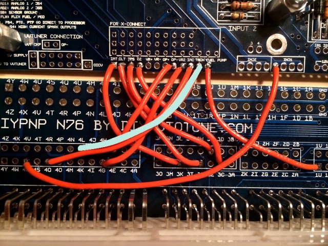
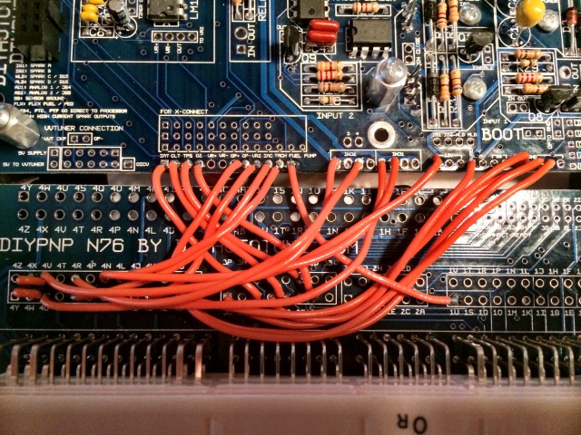
After completing the jumpers I can understand why some may find this a pointless posting since it is so straight forward, so I won’t go into any more step by step connections and will just post this image of the finished wiring. Both the radiator fan and A/C relay & fan are connected on the backside of the board so can’t be seen. I connected the radiator fan and A/C relay & fan following a slightly different rout than the instructions in the link above, following a path explained in another post. (shown below) I hope that it work out.
A/C
1K to Input 1 IN
Input 1 OUT to PE1
PA0 to 1B
1B to 1G
Radiator
WLD to Relay 1 IN
Relay 1 OUT to 1A
source: https://www.miataturbo.net/megasquir...p-c-r14-76265/
At this point in the game I am simply trying to run the DIYPNP on a stock set up in hopes to gain an understanding of tuning the car without any variables. From there I hope to get injectors and a fuel pump upgrade, and finally the FM 2kit down the road after I am confident using tunerstudio. That said, at this point (other than A/C) I think I’m going to be running a pretty “standard” set up, and hope the wiring looks OK to folks who’ve done this before.
Thanks in advance for your feedback.
Reply
1
1
04-01-2014, 08:20 AM
#6
Junior Member
Join Date: Nov 2010
Location: London, UK
Posts: 102
Total Cats: 0
Looks fine apart from WLED (see below). Just thought I'd add my thoughts on how I've done mine, based decisions on my layout on the input/output documentation from DIYPNP (DIYPNP Documentation - DIYAutoTune.com) and threads on here:
A/C Input:
1K (A/C Switch) > Input 1 IN
Input 1 OUT > FLX (PE0)
A/C Output:
ALED > 1B (Air Con Fan Relay) and 1G (A/C Pump Relay)
The reason I've used PE0 rather than the DiyAutotune suggested PA0 is so I can use PA0 for boost control in the future and not limit other possible uses for the inputs and outputs.
As I've deleted A/C now I'm doing a few changes, moving 1B (A/C Fan relay) to WLED so it comes on with Fan Control. It then frees up the A/C Switch input to PE0 to control something else.
Radiator Fan control:
WLED > 1A
WLED and ALED do NOT need to be output through a Relay circuit.
IAC:
Another random note, in Diyautotunes old basemap for 96-97 they didn't include a Diode in the pull up location for the IAC, this IS required (and I did confirm this with them).
I should note, I have had this running fine with GSlender and 3.3 releases but only on NA. I'm fitting the Turbo at the moment!
Reply
1
1
04-01-2014, 04:10 PM
#7
Newb
Thread Starter
Join Date: Mar 2014
Location: Boston
Posts: 13
Total Cats: 4
Thanks for the feedback Manic! I’m going to compare your notes to what I have and may make some changes per your suggestions. I also may end up deleting the A/C down the road but I guess I’ll see if I can get it running right first at least for wiring experience sake.
I did run a diode from IAC to 12V, with the banded end toward the 12V in the Pull Ups area. They must have updated the pin out map to reflect this so I should (hopefully) be OK.
Thanks again for your input man!!
I did run a diode from IAC to 12V, with the banded end toward the 12V in the Pull Ups area. They must have updated the pin out map to reflect this so I should (hopefully) be OK.
Thanks again for your input man!!
Reply
0
0
04-01-2014, 08:10 PM
#8
Junior Member
Join Date: Nov 2010
Location: London, UK
Posts: 102
Total Cats: 0
No worries dude. Mine IS wired up for A/C at the moment, I'm going to chop the connections and leave as pigtails inside the ECU with insulated bullets so it can be reconfigured to A/C if need be. If you want a gander at my excel sheet I can chuck it on dropbox.
Reply
0
0
04-02-2014, 12:07 PM
#9
Newb
Thread Starter
Join Date: Mar 2014
Location: Boston
Posts: 13
Total Cats: 4
Thanks man! That may be a great resource to reference. If it's not too much of a hassle that would be awesome.
Here my info: strombley79@gmail.com
Thanks again Manic!
Reply
0
0
05-02-2014, 09:02 AM
#11
Newb
Thread Starter
Join Date: Mar 2014
Location: Boston
Posts: 13
Total Cats: 4
Scott - I don't have enough posts yet to reply to your PM and I didn't want to leave you hanging, so please feel free to post any pin-out questions here and I'll gladly help out in any way I can until I can PM.
Thanks-Steve
Thanks-Steve
Reply
1
1


Thread
Thread Starter
Forum
Replies
Last Post
Mikel
MEGAsquirt
4
09-28-2015 04:46 PM


