More NB/MS2v3.0 questions
 04-09-2016, 06:06 PM
#1
Newb
Thread Starter

Join Date: Apr 2016
Posts: 18
Total Cats: 0
Hi,
Been doing a bit more digging to figure out how I will wire up my PCB3.0 with MS2 module. Think I've managed to find all the odds and ends I'll need now. Please can someone have a look and see if I'm on the right track? Ta
(1) SPARK MODS
Driving standard ignitors as described here: https://www.diyautotune.com/support/...rt-your-miata/
Seems to involve using the LED outputs with a pullup to 5V, one going to the IGN output and one going to IAC2B on the DB37.
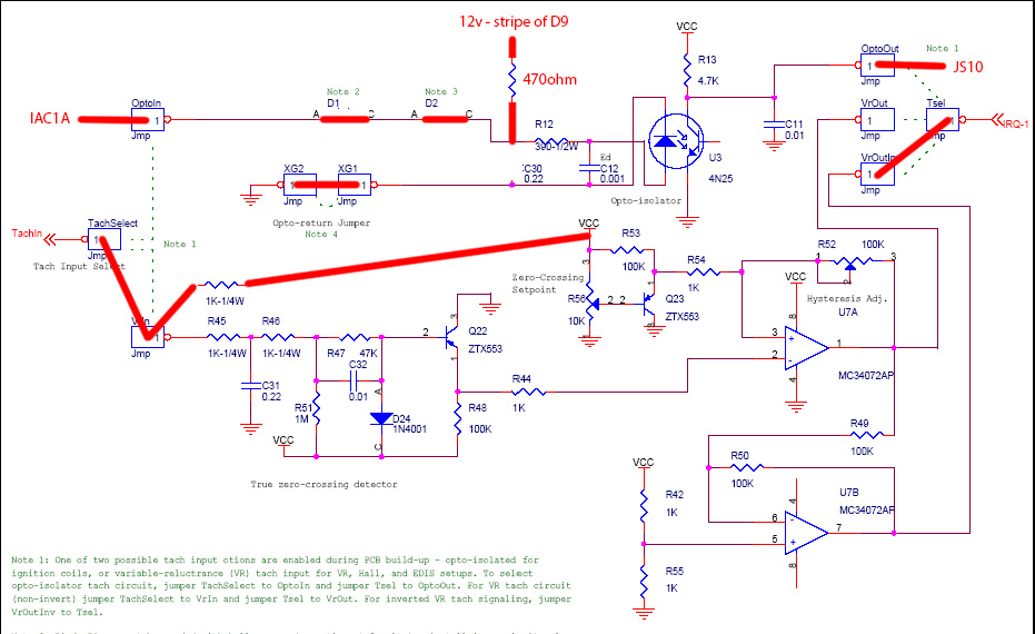
(2) VR/OPTO CIRCUITS:
Mods to pcb3.0 here: https://www.miataturbo.net/megasquir...2/#post1229126
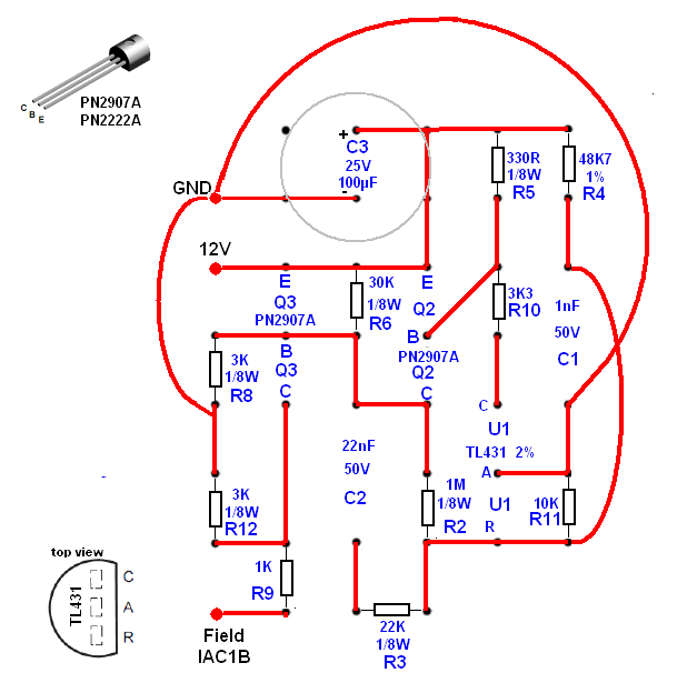
(3) ALTERNATOR FIELD DRIVE
From https://www.miataturbo.net/megasquir...2/#post1228016
(4) TACH OUTPUT CIRCUIT
From https://www.miataturbo.net/mspnp-55/...-output-64082/
Connect to spare port
QUESTIONS
- Does this look like it would work?
- The battery charge light on the dashboard is also controlled via the ECU, right? Any way to make that work?
- Does the stock knock sensor work with MS?
- The lambda sensor seems to have two wires going to the ECU in the wiring diagram I found - I think the other is for the heater. Do I need to connect that to 12 volts? I'll be fitting a wideband soon, but I want to get the stock narrowband to work just because
Hopefully I'm nearly there now... I managed to source the connector for the stock ecu (from mouser) so I'm hoping to build a little harness adapter cable so I can plug/unplug the stock ECU at will when testing this.
Been doing a bit more digging to figure out how I will wire up my PCB3.0 with MS2 module. Think I've managed to find all the odds and ends I'll need now. Please can someone have a look and see if I'm on the right track? Ta
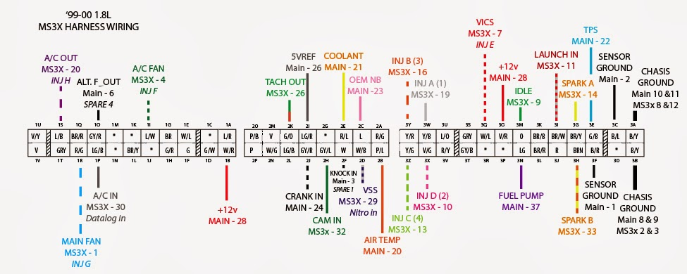
Code:
MEGASQUIRT PIN		MS PIN DESC	HARNESS PIN	DESCRIPTION				NOTE
==============          ===========	=======         ===========				====
28			+12V		1B		12 VOLT MAIN POWER
32			INJ 1		3W		INJECTOR A
32			INJ 1		3X		INJECTOR B
33			INJ 2		3Y		INJECTOR C
33			INJ 2		3Z		INJECTOR D
20			MAT		2B		INTAKE AIR TEMPERATURE SENSOR
21			CLT		2E		ENGINE COOLANT TEMPERATURE SENSOR
1			GROUND		3F		SENSOR GROUND
22			TPS		3E		THROTTLE POSITION SENSOR
26			5V REF		2I		T.P.S REFERENCE (5V?)
29			IAC2A		3Q		VICS SOLENOID VALVE
24			TACH		2J		CRANKSHAFT POSITION SENSOR		(2) VIA VR IN
25			IAC1A		2H		CAMSHAFT POSITION SENSOR		(2) VIA OPTO IN
36			IGN		3G		COILPACK 1				(1)
31			IAC2B		3H		COILPACK 2				(1)
6			SPR4		1O		GENERATOR FIELD				(3) JOE'S ALTERNATOR MOD?
3			SPR1		2F		KNOCK SENSOR				?????
30			FIDLE		3M		IACV					TIP120 FIDLE MOD
37			FUEL PUMP CTL	3N		FUEL PUMP RELAY
					1Q		CHARGE LIGHT
27			IAC1B		1R		COOLING FAN RELAY
					2K		TACH OUT TO CLUSTER			(4)
23			LAMBDA		2C		LAMBDA SENSOR
					1E		CHECK ENGINE LIGHT			NOT CONNECTED
2					3C		POWER GROUND
8,9					3A		POWER GROUND
10,11					3B		POWER GROUND
Driving standard ignitors as described here: https://www.diyautotune.com/support/...rt-your-miata/
Seems to involve using the LED outputs with a pullup to 5V, one going to the IGN output and one going to IAC2B on the DB37.
(2) VR/OPTO CIRCUITS:
Mods to pcb3.0 here: https://www.miataturbo.net/megasquir...2/#post1229126
(3) ALTERNATOR FIELD DRIVE
From https://www.miataturbo.net/megasquir...2/#post1228016
(4) TACH OUTPUT CIRCUIT
From https://www.miataturbo.net/mspnp-55/...-output-64082/
Connect to spare port
QUESTIONS
- Does this look like it would work?
- The battery charge light on the dashboard is also controlled via the ECU, right? Any way to make that work?
- Does the stock knock sensor work with MS?
- The lambda sensor seems to have two wires going to the ECU in the wiring diagram I found - I think the other is for the heater. Do I need to connect that to 12 volts? I'll be fitting a wideband soon, but I want to get the stock narrowband to work just because
Hopefully I'm nearly there now... I managed to source the connector for the stock ecu (from mouser) so I'm hoping to build a little harness adapter cable so I can plug/unplug the stock ECU at will when testing this.

Reply
 0
0

0
04-09-2016, 06:19 PM
#3
Newb
Thread Starter
Join Date: Apr 2016
Posts: 18
Total Cats: 0
I could do that... but then I've got a �400 doorstop which still hasn't found a home in a car yet.
I know it's not ideal, but let's say I don't mind going through the hassle of building the circuits... will they work?
I know it's not ideal, but let's say I don't mind going through the hassle of building the circuits... will they work?
Reply
0
0
04-19-2016, 07:25 AM
#4
Newb
Thread Starter
Join Date: Apr 2016
Posts: 18
Total Cats: 0
Sorry, just checked back at this thread, didn't realise you'd edited your post before.
It's a very early NB (1998), so no, NB1.
Started building the adapter cable and modding the board this week. Might even have it running soon.
It's a very early NB (1998), so no, NB1.
Started building the adapter cable and modding the board this week. Might even have it running soon.
Reply
0
0
04-19-2016, 08:06 AM
#5
Boost Czar


iTrader: (62)
Join Date: May 2005
Location: Chantilly, VA
Posts: 79,488
Total Cats: 4,077
i still highly recommend you buy the alternator control board from TSE and dont build it yourself.
https://www.miataturbo.net/miata-par...9/#post1322298
https://www.miataturbo.net/miata-par...9/#post1322298
Reply
0
0
 06-03-2016, 03:15 PM
#7
Newb
Thread Starter
Join Date: Apr 2016
Posts: 18
Total Cats: 0
OK - I'm still not 100% sure I'm doing the right thing with these cam and crank input circuits.
Going back to the start: My megasquirt is a standard MS2 with a PCB 3.0. The car is a 1998, which in the UK is an early mk2 (NB) car.
I want to use the standard cam and crank sensors.
Will the board mods I posted above work for these? I am confused because some people seem to build the "Abe/Jason C" signal conditioner circuits (which I still haven't found the schematics for) and then I see some people in other threads saying that the standard VR and opto-in will work fine with the two pullups added - does that apply for NB cars or not?
Sorry, but I am just totally, utterly lost. I know I could just get a PNP unit but megasquirts are expensive and I want to use what I have. Please, please could someone just tell me what I need to build? I could have the car running on megasquirt this weekend if I just had this information.
Thanks.
Reply
0
0
 06-07-2016, 04:38 PM
#9
Newb
Thread Starter
Join Date: Apr 2016
Posts: 18
Total Cats: 0
Triple post, durr!
Just wiring up the fuel pump; I have a 99-00 wiring diagram which is mostly correct except the light green '3N' wire (and a few others) are missing at the "3" plug on the ecu connector. What hell?
Does my 98 car have some weirdness in the way the pump control is setup? Anyone ever seen this before? (GUessing not, as you guys are mostly in the US and this seems to be a UKDM or 98 thing, but you never know.)
I guess I can find the pump relay and trace the wiring back from that, but I'm lazy.
Ta
EDIT: found it - it's the red/white wire at 3P.
Also found some broken pins on one of the connectors due to previous water damage, doh! fortunately i've sourced the correct pins so will re-pin them tonight.
just waiting on some vacuum line and then i can fire it up hopefully.
Last edited by TBJ; 06-09-2016 at 06:08 AM.
Reply
0
0
06-11-2016, 10:24 AM
#10
Newb
Thread Starter
Join Date: Apr 2016
Posts: 18
Total Cats: 0
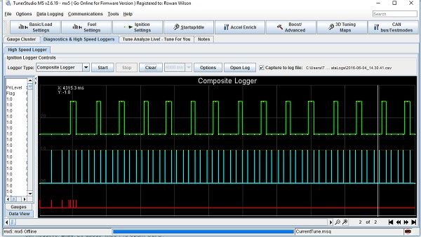
Got the car fired up today
The TL082 cam and crank circuits seem to work well, but I'm still not sure if they're overkill or if the two pullup resistors will work just as well. I did have to set the trigger angle offset to its maximum value (20 degrees) to retard the timing enough for it to fire up without suffering terrible kickback though.
Later on today I'll move the circuits from the little stripboards I built them on, into the proto area.
Reply
0
0
06-14-2016, 12:13 PM
#11
Newb
Thread Starter
Join Date: Apr 2016
Posts: 18
Total Cats: 0
Bueller?
Bueller?
...Anyone?
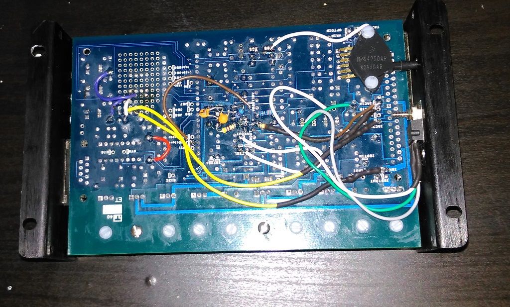
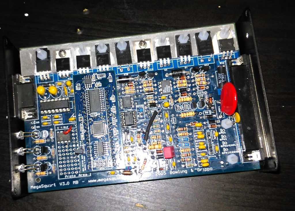
Got the board mods done. Popped the TL082 in where the standard op-amp would go and rejigged the standard input circuits to match the AbeFM/JasonC circuit.
Spark driver is on the proto area as well. IAC driver is bolted to the case.
Should be plenty of room left for the alternator control stuff, which I'm gonna have a crack at building myself.
Bit messy, but it all works.
By the way - the weird timing issue seemed to be caused by the spark dwell, which is set to 8ms while cranking in the DIYautotune base map. Changed it to 3 and all is good.
Just need to sort out the alternator control now.
Some pictures of what I've done so far, in case they're useful to anyone...
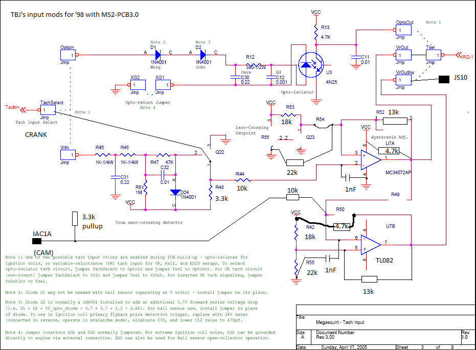
Use "schematic" at own risk, I will release a neater version at some point.
Bueller?
...Anyone?
Got the board mods done. Popped the TL082 in where the standard op-amp would go and rejigged the standard input circuits to match the AbeFM/JasonC circuit.
Spark driver is on the proto area as well. IAC driver is bolted to the case.
Should be plenty of room left for the alternator control stuff, which I'm gonna have a crack at building myself.
Bit messy, but it all works.
By the way - the weird timing issue seemed to be caused by the spark dwell, which is set to 8ms while cranking in the DIYautotune base map. Changed it to 3 and all is good.
Just need to sort out the alternator control now.
Some pictures of what I've done so far, in case they're useful to anyone...
Use "schematic" at own risk, I will release a neater version at some point.
Reply
0
0
06-27-2016, 05:13 PM
#12

I'm going to tag along with this discussion since it's highly NB wiring oriented. I am in the middle of re-jumpering my DIYPNP MS2 for my 2000 (converting over from 94-95 wiring) utilizing the pin out provided here: https://www.diyautotune.com/support/...0-mazda-miata/ when it came time to hook up a few of the jumpers for my custom stuff like clutch switch and a few other items I wanted to wire into my LC-2 I realized that just about every single connection is wrong in that provided diagram. I'm looking at this thread and this wiring diagram: http://www.yorbalindamiata.com/images/wiring/2000wire.pdf and they seem to agree.
How in the $%*&@ has that termination list been on DIYautotune's website for this long and been completely wrong? Just want a sanity check before I redo all my jumpers for a 2nd time.
How in the $%*&@ has that termination list been on DIYautotune's website for this long and been completely wrong? Just want a sanity check before I redo all my jumpers for a 2nd time.
Reply
0
0
06-28-2016, 09:23 AM
#13
Supporting Vendor

Join Date: Sep 2006
Posts: 2,332
Total Cats: 67
One big note - the termination in the chart uses the numbering on the DIYPNP adapter board. Mazda's factory diagrams are often for 2 or 3 connector versions, resulting in different numbers unless you convert them over.
Reply
0
0
06-28-2016, 11:01 AM
#16
Senior Member
iTrader: (1)

Join Date: Dec 2010
Location: Farmington Hills, MI
Posts: 1,218
Total Cats: 175
The numbers aren't wrong, just different. DIYPNP documentation is going to use the same number configuration for every vehicle it's made for, and some vehicle use more than the 2 or 3 connectors that the Miatas use. It's pretty obvious from the two links you posted. IAT is 3B on the DIYPNP and 2B in the wiring diagram. TPS is 4E on the DIYPNP and 3E in the diagram. Condenser fan relay is 1I in both DIYPNP and diagram. Miata 1 is DIYPNP 1, Miata 2 is DIYPNP 3, Miata 3 is DIYPNP 4.
Reply
0
0