Resurrecting a "dead" MS3 - Questions
 09-11-2013, 12:47 PM
#1
Senior Member
Thread Starter

Join Date: Dec 2007
Location: ATL
Posts: 1,348
Total Cats: 128
I'm a MS virgin and I (think I) found a way to get some experience with a DIY kit without taxing my poor soldering skills too badly.
[You can skip right to the question if you aren't interested in my story...]
Anyway...the story; I have a 99 with a FM Voodoo kit I installed last year in place of a trusty old M45 SC install. I did this so that I could change one thing at a time and not overwhelm myself. Now that I have the basics of the turbo straight, it's time to "go big" and replace the Voodoo box with a MS - which was my intent all along.
I really wanted to get a built-up box (either directly from DIY, or from Rev) but my cash-flow is not the best (new job, relocation, etc...) and I'm not that good a solderer so I was afraid of building a DIY kit from scratch.
So, when I saw a local guy was selling a failed DIY MS3 intended for a '01 for a steal, I bought it. My thinking was; a) it'll get me familiar with the internals of the box, b) the "fail" might not be so terrible that I can't find and fix it,, and c) the experience is worth the price I paid for the unit regardless if I botch it or not.
So far, I've found a couple of misplaced jumpers, but I have a question.
The Question:
In the instructions, and on the motherboard, two potentiometers are indicated; R52 and R56. However on the board that I have, the space where R52 is, there are two resistors wired in series and R56 has nothing there at all.
So...I've searched, and have found nothing similar anywhere. Was there any time when something like this was common? Should I get the right pots, rip this out and fix it?
Waiting for words of wisdom (or flames)....As I proceed there will probably be other, similar questions.

Reply
 0
0

0
09-11-2013, 01:24 PM
#2

The crank sensor input is most likely going through the opto-isolator circuit. Many Miata specific ms1 and ms2 were built that way. However, ms3 are usually built to use the newer vr conditioner circuit which includes r52 and r56. You can use either circuit with the stock Miata cas.
I suggest you post a picture of the mainboard.
I suggest you post a picture of the mainboard.
Reply
0
0
09-11-2013, 05:59 PM
#3
Senior Member
Thread Starter
Join Date: Dec 2007
Location: ATL
Posts: 1,348
Total Cats: 128
Pictures?
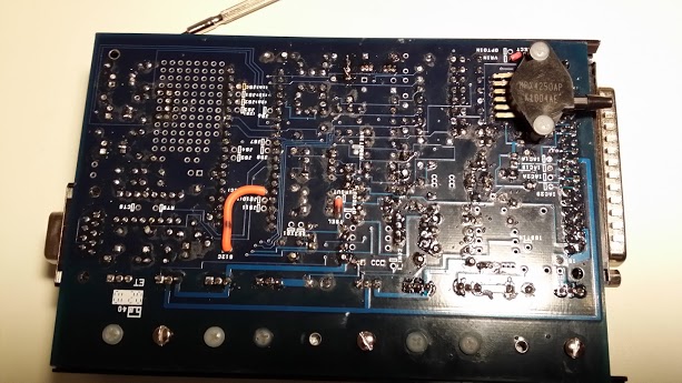
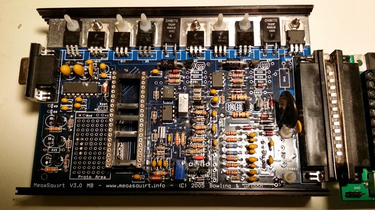
Well here are some pics of my aborti..., I mean "my" MS
Top

Bottom

You'll see;
- Lots of cut jumpers
- The missing pots & R52 & 56
- "Weirdness" in the stack of resistors under D3
- No LEDs in D14-16
- You can't see that the "header" where the daughterboard mates on U1 is melted from what seems to be a repair there.
All in all, I think this will be a real "science project"
Well here are some pics of my aborti..., I mean "my" MS
Top
Bottom
You'll see;
- Lots of cut jumpers
- The missing pots & R52 & 56
- "Weirdness" in the stack of resistors under D3
- No LEDs in D14-16
- You can't see that the "header" where the daughterboard mates on U1 is melted from what seems to be a repair there.
All in all, I think this will be a real "science project"
Reply
0
0
09-12-2013, 01:34 PM
#4
It looks like it was wired for a ms2 with a custom opto ckt for the crank input.
You can either (1) figure out the custom ckt (ask the PO and/or read the MS schematics and compare to your board) and wire it accordingly OR (2) remove those components and build one of the standard crank input ckts (vr or opto-isolator) from the MS documentation.
Option (2) will require more desoldering and soldering of course.
Do you plan to use the ms3x expander board?
Reply
0
0
09-12-2013, 02:16 PM
#5
Senior Member
Thread Starter
Join Date: Dec 2007
Location: ATL
Posts: 1,348
Total Cats: 128
I think I'll go with a standard config (I just ordered a Weller soldering station this morning) and bite the bullet. I'm thinkg it'll be easier to debug future issues without dealing with customizations.
For starters, I was thinking of just building up the MS3 (w/o the expander) - again, to limit the complexity, and taxing my noobosity, for the short term. Getting an operational MS is primary, then comes the whole arena of tuning it (w/o blowing up my engine). From what I understand, I can add in the expander card at a later time - correct?
Guess I'll use this space to document progress and ask questions as I proceed...
Reply
0
0
10-02-2013, 03:42 PM
#6
Senior Member
Thread Starter
Join Date: Dec 2007
Location: ATL
Posts: 1,348
Total Cats: 128
Ok...been a while, but I haven't been idle. I spent about a week trying to understand what had been done. I even bought a Jimstim to see if I could "bench test" the thing - with little or no success. I don't know if that was because of my limited understanding (probably), or if the MS itself was junk (possibly).
So I threw up my hands, and began to document what ws different from my box and a "stock" MS build - and the differences were significant. Significant enough that I decided to remove everything that wasn't "stock" (for a DIY MS3), buy parts from DIYautotune, and start over.
My parts should arrive today or tomorrow and I'll probably dive into the disassembly this weekend. I'll document my process here - if anyone's interested...
Reply
0
0
10-02-2013, 05:01 PM
#7
Boost Czar


iTrader: (62)
Join Date: May 2005
Location: Chantilly, VA
Posts: 79,493
Total Cats: 4,080
the input circuit was modded for Abe's NB input.
Id revert it back to a true VR input as designed, then remove all other jumpers.
run 1 jumper from s12c to js9. and 1K from 5v to the VRIN. and slap in a ms3 daughterboard and expander.
Id revert it back to a true VR input as designed, then remove all other jumpers.
run 1 jumper from s12c to js9. and 1K from 5v to the VRIN. and slap in a ms3 daughterboard and expander.
Reply
0
0
10-03-2013, 10:03 AM
#8
Senior Member
Thread Starter
Join Date: Dec 2007
Location: ATL
Posts: 1,348
Total Cats: 128
run 1 jumper from s12c to js9. and 1K from 5v to the VRIN. and slap in a ms3 daughterboard and expander.
Reply
0
0
10-09-2013, 09:19 AM
#10
Senior Member
Thread Starter
Join Date: Dec 2007
Location: ATL
Posts: 1,348
Total Cats: 128
Progress Report;
I got to step 55 in the Megamanual, where it's time to hook up the Jimstim and check the RPM signal...and got nothing. The WBO2 signal and temp signals change when I turn their respective pots, but the RPM signal is nada.
I've turned the R52 and R56 pots every whichway. I've turned off all the switches on the DIP. I've set the Tunerstudio ignition options to "Basic trigger". I built the VR conditioner on the MS board, and have the VR jumper in-place (with and without the pull-up jumpers). I've done the stand-alone tests of the RPM signal on the Jimstim, and they check out.
The only thing I haven't done is try to check the RPM signal path on the MS mainboard itself...because I'm an electronic klutz and have tapped out my skillset. I took one look at the mainboard schematic and freaked - I have no clue as to how to check signals on the board. My electronic knowledge is limited, and I only have a DMM as a tool.
So...where do I go from here? I have pics of my build so far if that'll help.
Reply
0
0
10-09-2013, 09:38 AM
#11
Boost Czar
iTrader: (62)
Join Date: May 2005
Location: Chantilly, VA
Posts: 79,493
Total Cats: 4,080
remove the d2 jumper.
remove r13.
jump the left hole (as pictured) of r13 with a 1K resistor to the right hole of the resistor below it (r45).
everything else looks good. Dunno how you expect to get anything on the stim without a CPU hooked up...
for the pots, turn them both 12 CCW. then turn the bottom one, r52, CW 7 turns.
Reply
0
0
10-09-2013, 08:45 PM
#14
Senior Member
Thread Starter
Join Date: Dec 2007
Location: ATL
Posts: 1,348
Total Cats: 128
Ok, I removed R13 and put the 1K resistor from the left hole of R13 to the right side of R45 (D2 jumper still in) and...nothing.
Just in case I screwed up and put in R52 and/or R56 backwards, I turned them both CW and then backed out R52 CCW. And still...nothing.
I cut the D2 jumper with the same result.
PS-in all of this I tried the 12v pull-up and the 5v pull-up...no difference.
On another forum (no, not m.net!) I got the response, "start tracing the signal". Well, being an electronics-challenged noob, I soldered one side of an LED to the GND on the proto area and the other side to a length of wire to use as a makeshift probe and started poking around the board with the mainboard schematic by my side.
I can't say that I really learned anything (because I don't know what I was doing). But I could light up the LED when I touched one side of several resistors associated with the tach input signal.
After that, I powered off the Jimstim and started measuring resistance across some of those same resistors and found that R53 was the wrong value (17K instead of 10K). I replaced that (to none effect), but that leads me to believe that there might be more "wrong" resistors (and if they are wrong, there's no reason to trust the diodes or the caps - in fact, the whole thing might be crap!).
Resistors I can measure, but I don't have a clue about anything else (as in "electrically challenged"). I might be DOOMED!
Reply
0
0
10-10-2013, 07:55 AM
#15
Boost Czar
iTrader: (62)
Join Date: May 2005
Location: Chantilly, VA
Posts: 79,493
Total Cats: 4,080
What firmware do you have loaded on your CPU? and what map do you have loaded? and do you have the jumpers and dip switches on your stim setup correctly?
youre making this harder than it is. slap the cpu in, install the expander, load firmware, load a basemap setup for a 99-00 miata, set the dip switches correctly to mimic that trigger wheel, send the second trigger to pin 32 of the expander, open tuner studio, connect the MS, turn on the stim and see if you're getting rpms.
Reply
0
0
10-10-2013, 07:58 PM
#16
Senior Member
Thread Starter
Join Date: Dec 2007
Location: ATL
Posts: 1,348
Total Cats: 128
they need to be turned 12 turns CCW first, then R52 gets 7-8 turns CW.
What firmware do you have loaded on your CPU? and what map do you have loaded? and do you have the jumpers and dip switches on your stim setup correctly?
youre making this harder than it is. slap the cpu in, install the expander, load firmware, load a basemap setup for a 99-00 miata, set the dip switches correctly to mimic that trigger wheel, send the second trigger to pin 32 of the expander, open tuner studio, connect the MS, turn on the stim and see if you're getting rpms.
I'm running the v1.1.2 firmware, and I've repeated all of this with several different maps (only because the MS isn't in the car, and won't be until I can get it operating on the bench); the MS3extra map fro DIYAutoTune, a copy of Frank's map for a '99 and the base tune that came with the firmware download.
I set the DIP switches as follows (according to the jbperf site);
1-off
2,3-on
4,5-off
6-on
7,8-off
I don't have a MS3x expander board (will this "magically" make the RPM signal appear - I thought I could get this rig running w/o it).
I may be overthinking this, but nothing is working so far...
if you want the maps, I've attached them
I'm almost at the point of calling this a fail and buying a PNP gen2 for my Christmas present.
Reply
0
0
10-11-2013, 07:43 AM
#17
Boost Czar
iTrader: (62)
Join Date: May 2005
Location: Chantilly, VA
Posts: 79,493
Total Cats: 4,080
well you have no second trigger at the moment.
when connected, click the diagnostics tabs and start a composite log.
manipulate the rpm pot until you get some activity on the plot screen (should see record 1 of 1 on the bottom). I bet you have just a blue line and a red line and no green line on the top. the red line indicating where the MS was expecting a single but didn't get it. so you're not syncing.
Are you going to get an expander? i thought you said you had one. otherwise it'll take a lot of effort to build all the circuits you need to have your ms3 actually useful, like seq. fuel and spark and all the inputs and outputs you need.
Reply
0
0
10-11-2013, 08:42 AM
#18
Senior Member
Thread Starter
Join Date: Dec 2007
Location: ATL
Posts: 1,348
Total Cats: 128
Guess who just discovered the logging function...too late to examine anything last night (so I have homework to do tonight).
Don't have an expander (yet), I was hoping to get beyond where I am now before investing in that - every dollar not spent now would go towards a PNP box if I can't make this one work.
Don't have an expander (yet), I was hoping to get beyond where I am now before investing in that - every dollar not spent now would go towards a PNP box if I can't make this one work.
Reply
0
0
 and I don't have a whole lot of hair left on my head to pull out!


