MS3, MS3x, for a 2002. What to buy?
 02-13-2011, 09:39 AM
#61
Elite Member

Thread Starter
iTrader: (3)

Join Date: Apr 2008
Location: Outside Portland Maine
Posts: 2,023
Total Cats: 19
Don't worry, I absolutely will. I just have to go out and find a variable power supply. The one I thought would work only goes down to 15 volts, so it won't work.

Reply
 0
0

0
02-13-2011, 10:40 AM
#62
2 Props,3 Dildos,& 1 Cat

iTrader: (8)
Join Date: Jun 2005
Location: Fake Virginia
Posts: 19,338
Total Cats: 573
you can use that. just whip up a voltage divider with a potentiometer. the circuit doesn't require a lot of power for testing. you just need to know voltage in and voltage out.
when the output turns on as you drop below 14.2V input voltage, you're golden.
when the output turns on as you drop below 14.2V input voltage, you're golden.
Reply
0
0
02-17-2011, 12:45 PM
#63
Elite Member
Thread Starter
iTrader: (3)
Join Date: Apr 2008
Location: Outside Portland Maine
Posts: 2,023
Total Cats: 19
Well, I made the voltage divider (actually just using a 24 power supply and a pot) and the circuit doesn't work and I can't for the life of me figure out why. I made it exactly like the picture posted above, and checked all the bands on all the resistors, and I get 0V across field and GND, and I get whatever supply voltage is across field and 12V. I get 0A across field and GND and somewhere between 0 an 4mA across field and 12V, with no cutoff when supply is at 14.4 (or anywhere else for that matter). Any ideas what to check? I have a simple multimeter and my eyes and a magnifying glass to use.
Reply
0
0
02-17-2011, 01:30 PM
#64
Elite Member
Thread Starter
iTrader: (3)
Join Date: Apr 2008
Location: Outside Portland Maine
Posts: 2,023
Total Cats: 19
Well, I did it again. I figured out the problem 3 minutes after I got so frustrated I had given up and posted here. Then I looked at it once more and noticed something I hadn't noticed before, and now it seems to work great.
Reply
0
0
02-17-2011, 01:40 PM
#66
Elite Member
Thread Starter
iTrader: (3)
Join Date: Apr 2008
Location: Outside Portland Maine
Posts: 2,023
Total Cats: 19
Seems to be between 14V and 14.5V, if you mean the supply voltage when the current (and voltage) at field drops to zero. The pot I had makes voltage variation between 10 and 24V very difficult, but after a few attempts, I never saw more than about 14.3 before the field dropped to zero.
Reply
0
0
02-17-2011, 03:02 PM
#68
Elite Member
Thread Starter
iTrader: (3)
Join Date: Apr 2008
Location: Outside Portland Maine
Posts: 2,023
Total Cats: 19
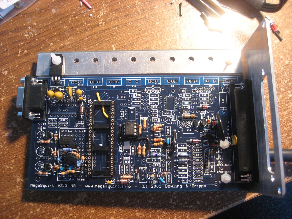
I just tried out the MAP sensor with a rubber bulb thing and it doesn't register in TS at all, which makes me wonder if it's actually a problem with the stim, or a problem with my board. Below is a picture of my board, does anybody notice anything missing or wrong? I'm guessing that whatever I did, if anything, is pretty substantial since NONE of the sensors are registering anything but they are all giving some reasonable value (MAP reads 91kPa, CLT and MAT read 115F, and TPS reads 325).
Reply
0
0
02-17-2011, 03:08 PM
#69
mkturbo.com

iTrader: (24)
Join Date: May 2006
Location: Charleston SC
Posts: 15,176
Total Cats: 1,680
I just tried out the MAP sensor with a rubber bulb thing and it doesn't register in TS at all, which makes me wonder if it's actually a problem with the stim, or a problem with my board. Below is a picture of my board, does anybody notice anything missing or wrong? I'm guessing that whatever I did, if anything, is pretty substantial since NONE of the sensors are registering anything but they are all giving some reasonable value (MAP reads 91kPa, CLT and MAT read 115F, and TPS reads 325).

Reply
0
0
02-17-2011, 03:17 PM
#70
Elite Member
Thread Starter
iTrader: (3)
Join Date: Apr 2008
Location: Outside Portland Maine
Posts: 2,023
Total Cats: 19
Wow, look at that. I don't know how I managed to skip all of that! I found it and I'm installing that part now. Thanks for pointing out the obvious for me, who knows how long it would have taken me.
Reply
0
0
02-17-2011, 03:22 PM
#71
2 Props,3 Dildos,& 1 Cat
iTrader: (8)
Join Date: Jun 2005
Location: Fake Virginia
Posts: 19,338
Total Cats: 573
C2 thru C10 are all for basic sensors.
same with the row of resistors to their left.
http://www.msextra.com/doc/general/ms3v3schems.html
this is also helpful i knowing what goes to what:
http://www.megamanual.com/ms2/V3assemble.htm
between those two links, you should be able to determine what to include and exclude.
This may or may not be the final version of mine. I think it doesn't have the NB trigger circuitry yet:
Reply
0
0
02-17-2011, 03:27 PM
#72
mkturbo.com
iTrader: (24)
Join Date: May 2006
Location: Charleston SC
Posts: 15,176
Total Cats: 1,680
Basically you followed just Frank's directions and left out some stuff from the megamanual. He does not say to go back and do the steps he does not mention in his write up.
Reply
0
0
 02-17-2011, 05:03 PM
#77
Elite Member
Thread Starter
iTrader: (3)
Join Date: Apr 2008
Location: Outside Portland Maine
Posts: 2,023
Total Cats: 19
There is no need to do "Joe's Spark Circuit".
When you buy the MS3 kit and MS3x, they come with the DB37 connectors you need to make a harness. Talk to y8s about the mazda ECU connector, I think he has a spare.
The Input Circuit you DO need to add is this one outlined here: http://westfieldmx5.devocht.com/index.php?section=35
see Step 50.
You will also need to do the alternator control circuit outlined above.
Also very little needs actually be populated on the mainboard, so save yourself the trouble when building it and omit the circuits that are pointless. It should also be outlined on the build thread linked above.
Don't follow any other "additional/optional circuits" or the step 65.
Reply
0
0
02-17-2011, 05:15 PM
#78
Elite Member
Thread Starter
iTrader: (3)
Join Date: Apr 2008
Location: Outside Portland Maine
Posts: 2,023
Total Cats: 19
And what is the thought on cleaning the flux off the board? Is it necessary, and if so why? I never did it on my MS1, but I only had it for a couple years.
Reply
0
0
02-17-2011, 05:41 PM
#79
2 Props,3 Dildos,& 1 Cat
iTrader: (8)
Join Date: Jun 2005
Location: Fake Virginia
Posts: 19,338
Total Cats: 573
I wired up the LEDs as standard. One of them I use for an output, but they can magically be both.
find the purest isopropyl alcohol and an old toothbrush and clean that flux!
find the purest isopropyl alcohol and an old toothbrush and clean that flux!
Reply
0
0


