MS3 no-sync 60-2 wheel + cam sensor
 11-13-2011, 04:27 PM
#1
Junior Member
Thread Starter

Join Date: Dec 2006
Location: NH
Posts: 114
Total Cats: 1
Finally finished wiring my MS3 + DIYBOB in my 1994.
Have VR+pullup for crank sensor, sawed off CAS with pullup for cam.
Tested MS3 sees sensor inputs with JimStim.
Using CNP with DIYAutoTune IGN-1A coils. Coils we tested with MS3.
No trigger/no sync, etc in vehicle. The ignition logger runs but stays blank. I know the crank sensor and cas work, or at least they did - had been using it with my TEC3.
Some sensors work - MAP, TPS, coolant, air temp.
I don't hear the fuel pump come on. Probably because no crank, right?
What is the best way to go about diagnosing this? Scope the best way? Haven't got one at home, I can borrow one from work. Anything I can try without a scope?

Reply
 0
0

0
11-13-2011, 05:49 PM
#2
Supporting Vendor


iTrader: (33)
Join Date: Jul 2006
Location: atlanta-ish
Posts: 12,659
Total Cats: 134
I've never seen a TEC EMS that used a hall effect CKP sensor. Sounds like you set up the CKP input circuit incorrectly. IOW, you need to set up your CKP input for VR.

Reply
0
0
11-13-2011, 07:40 PM
#3
Junior Member
Thread Starter
Join Date: Dec 2006
Location: NH
Posts: 114
Total Cats: 1
What is CKP? My FSM refers to the Crankshaft Positioner Sensor signals as SGC and SGT. SGC has 2 pulses per revolution and SGT has 4 pulses.
The TEC3 used a 60-2 wheel with VR for the crank. I used a miata CAS (hall) with with a sawed off arm for sequential for the TEC3. (SGC)
So I set up the MS3 for VR+pullup for the crank. I'm using the SGC signal on CAS (sawed off) for the CAM signal. I am not using the SGT signal.
I get no signals at all on the ignition logger.
Reply
0
0
11-14-2011, 08:58 PM
#4
Supporting Vendor
iTrader: (33)
Join Date: Jul 2006
Location: atlanta-ish
Posts: 12,659
Total Cats: 134
CKP sensor
Right.
Why did you set up your input for a hall sensor when you have a VR sensor?
So in other words...
You're not going to get a tach input signal until you fix this. Here is what you need to do (I'm assuming you built a V3.0)...
V3.0 board - VR Input
a) Solder a link between VRIN and TACHSELECT
b) Solder a wire between VrOUT and TSEL
c) With a small screwdriver, turn the pots, R52 and R56, about 12 turns to the fully anticlockwise position (you may feel a "click" when the end position is reached, they can't be damaged by turning too far.) This sets them up for most VR sensors.

Right.
Why did you set up your input for a hall sensor when you have a VR sensor?
So in other words...
V3.0 board - VR Input
a) Solder a link between VRIN and TACHSELECT
b) Solder a wire between VrOUT and TSEL
c) With a small screwdriver, turn the pots, R52 and R56, about 12 turns to the fully anticlockwise position (you may feel a "click" when the end position is reached, they can't be damaged by turning too far.) This sets them up for most VR sensors.
Reply
0
0
11-14-2011, 09:17 PM
#5
Junior Member
Thread Starter
Join Date: Dec 2006
Location: NH
Posts: 114
Total Cats: 1
Are you saying that VR+pullup = hall ? 
That was not real obvious in the documentation. Clearly I missed it.
So I need to clip the pullup. Funny, that was my original configuration. No trigger there either. Maybe I did not have the pots set right.
Thanks
-Bruce
That was not real obvious in the documentation. Clearly I missed it.
So I need to clip the pullup. Funny, that was my original configuration. No trigger there either. Maybe I did not have the pots set right.
Thanks
-Bruce
Reply
0
0
11-18-2011, 08:54 AM
#6
Boost Pope

iTrader: (8)
Join Date: Sep 2005
Location: Chicago. (The less-murder part.)
Posts: 33,024
Total Cats: 6,591
Any hall sensor (or any sensor with an open-collector output, for that matter) requires a pullup. Pure VR sensor, by comparison, generate a voltage all by themselves.
Technically, the circuit Ben is pointing you to was originally designed to take a VR sensor, however if you apply a pullup at the front end and adjust the zero-crossing pot to near the top of the range (such it's providing a bias of greater than 2 volts to the (+) input of the op-amp) then that circuit can also work with a hall-type sensor.
Technically, the circuit Ben is pointing you to was originally designed to take a VR sensor, however if you apply a pullup at the front end and adjust the zero-crossing pot to near the top of the range (such it's providing a bias of greater than 2 volts to the (+) input of the op-amp) then that circuit can also work with a hall-type sensor.
Reply
0
0
11-19-2011, 01:39 PM
#7
Junior Member
Thread Starter
Join Date: Dec 2006
Location: NH
Posts: 114
Total Cats: 1
Still no VR output. Got a USB scope, I'll take a look at it this afternoon.
I'm not sure I've wired everything right. Everything checked out on my JimStim.
At key on, is the fuel pump supposed to go on? My TEC3 always fired up the fuel pump at key on.
My fuel pump doesn't turn on at key on. I understand that the fuel pump should go off if the ecu had not received any crank pulses for some time.
What signals are required at key on for the fuel pump to come on?
Reply
0
0
11-20-2011, 06:19 PM
#8
Junior Member
Thread Starter
Join Date: Dec 2006
Location: NH
Posts: 114
Total Cats: 1
Scoped the Sensor output. +/- 400 mV during crank. Nothing out of the VR circuit. Probed the circuit to find out what was wrong.
I went to probe the circuit at R47. It wasn't there. Assembly error... Spent 20 minutes looking for resistor. Actually found it. Then freaking lost it in the garage. Spent another 10 minutes looking for the tiny plastic bag. Finally soldered in the resistor.
Too dark to connect everything together in the driveway - hope to fire it up tomorrow.
Reply
0
0
11-21-2011, 03:07 PM
#9
Junior Member
Thread Starter
Join Date: Dec 2006
Location: NH
Posts: 114
Total Cats: 1
Gahhh... This has been painful. Finally got the VR to trigger. Had to use a scope to set the trigger point. Standard setpoint did not work - it was too low. Had to raise it so I'd get crank.
CAM does not seem to trigger. Jumper JP7 for pullup is in.
When I turn the pot R11, the voltage at the ZC test pad does not change. Is that normal? That is not the way the circuit behaved on the V3.0 board.
What could cause a fixed (80mV) output at ZC?
CAM does not seem to trigger. Jumper JP7 for pullup is in.
When I turn the pot R11, the voltage at the ZC test pad does not change. Is that normal? That is not the way the circuit behaved on the V3.0 board.
What could cause a fixed (80mV) output at ZC?
Reply
0
0
11-27-2011, 02:25 PM
#11
Junior Member
Thread Starter
Join Date: Dec 2006
Location: NH
Posts: 114
Total Cats: 1
I seem to not have sync errors. Had a lot of operator errors, including how to run usb scope. usb scope is a lot harder and slower than a real scope.
What kind of problem? no cam/cas or?
What kind of problem? no cam/cas or?
Reply
0
0
11-27-2011, 03:55 PM
#13
Junior Member
Thread Starter
Join Date: Dec 2006
Location: NH
Posts: 114
Total Cats: 1
Well I know how you feel. Been screwing with this for a week now. My other thread needs a title change to NO Start, rather than first start.
Do you have the pull up on the CAM signal? There is a jumper on the ms3x that you install. I think it is there by default. Nothing on the tooth logger?
I used a scope to make sure the CAS signal was at the ms3x input. Is there a signal at input?
Have a JimStim? That simplifies things.
Do you have the pull up on the CAM signal? There is a jumper on the ms3x that you install. I think it is there by default. Nothing on the tooth logger?
I used a scope to make sure the CAS signal was at the ms3x input. Is there a signal at input?
Have a JimStim? That simplifies things.
Reply
0
0
11-27-2011, 08:09 PM
#14
Boost Pope
iTrader: (8)
Join Date: Sep 2005
Location: Chicago. (The less-murder part.)
Posts: 33,024
Total Cats: 6,591
Late to the party again...
I had the same problem on Emilo's new car. They'd set it by the book, but the actual voltage at the opamp was under 1v.
Regarding the earlier question about the ZC pad:
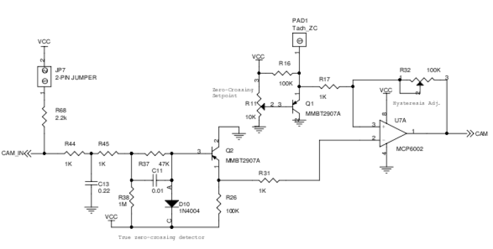
Not much that could prevent this from working properly apart from a bad connection, a missing part, or a shorted Q1 / U7.
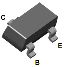
You could try probing at the base of Q1 just to be sure that you are getting a voltage out of R11. It's the pin labeled B:
80mv doesn't make any sense- the VBE on a MMBT2907A would be in he hundreds of millivolts.
Originally Posted by SlowRider
Had to use a scope to set the trigger point. Standard setpoint did not work - it was too low.
Regarding the earlier question about the ZC pad:
Not much that could prevent this from working properly apart from a bad connection, a missing part, or a shorted Q1 / U7.
You could try probing at the base of Q1 just to be sure that you are getting a voltage out of R11. It's the pin labeled B:
80mv doesn't make any sense- the VBE on a MMBT2907A would be in he hundreds of millivolts.
Reply
0
0
11-28-2011, 10:21 AM
#15
Junior Member
Thread Starter
Join Date: Dec 2006
Location: NH
Posts: 114
Total Cats: 1
Joe, just measured 2.00 V at the base of the transistor. Only 80mV at the output ZC TP. Measured with a digital VOM. The 80mV measurement is the same as when I measured with the crummy usb scope. Bad transistor? Anything else I could measure? Should I set the voltage higher?
Reply
0
0
11-28-2011, 10:34 AM
#16
Junior Member
Thread Starter
Join Date: Dec 2006
Location: NH
Posts: 114
Total Cats: 1
Funny thing though, sometimes ZC measures 2.69V, with a base of 2.04V, which gives a decent Vbe. After starting, it seems to latch up and give ZC=50-80mV. Is this probably U7 latchup? I don't think I've seen such a simple transistor behave this way. When I get CAM activity it tries to start. No cam, no start.
What do I change? Where to find parts?
What do I change? Where to find parts?
Reply
0
0
11-28-2011, 10:52 AM
#17
Junior Member
Thread Starter
Join Date: Dec 2006
Location: NH
Posts: 114
Total Cats: 1
Hmm, the key was to fiddle with hysteresis. I just moved it a little bit, and the system changed state. Then I reset the R11 pot and ZC started moving. Beats me why it works that way... Have big cam signal now...
Reply
0
0
 11-28-2011, 11:36 AM
#19
Junior Member
Thread Starter
Join Date: Dec 2006
Location: NH
Posts: 114
Total Cats: 1
My other thread has the ignition log. I'll attach it here too.
Where is the rising (or falling edge) supposed to be for the cam? 120 degrees before TDC? Which way should I rotate the cas?
CAM signal out is not reliable... some logs show it stuck low in weird places.
I have no GD idea how to set this CAM signal properly...
Where is the rising (or falling edge) supposed to be for the cam? 120 degrees before TDC? Which way should I rotate the cas?
CAM signal out is not reliable... some logs show it stuck low in weird places.
I have no GD idea how to set this CAM signal properly...
Last edited by SlowRider; 11-28-2011 at 12:20 PM. Reason: update to note cam not reliable...
Reply
0
0


