MS3 pro module PnP adapter board
 02-19-2014, 07:01 AM
#1
Senior Member
Thread Starter

Join Date: Nov 2007
Location: Belgium
Posts: 999
Total Cats: 73
Probably not many using the MS3 pro module, but I thought I'd show what I'm working on for my '99.
Currently, my MS3 pro module looks like this:
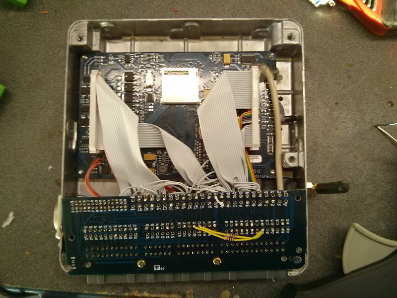
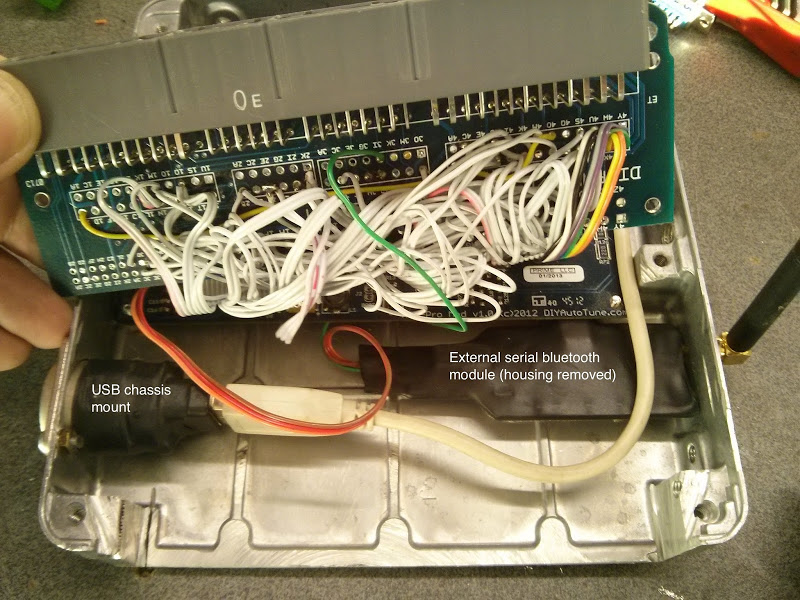
I works fine, but it's kinda a bit of a mess so I'm thinking of making some kind of an adapter board.
Here's where I'm at right now. Map sensor, alternator circuit, usb and serial onboard.
It's far from done because I don't have a stock ecu to take exact measurements from.
Thinking of an internal usb module, but I'm not sure how those modules perform when inclosed in a metal case.
I have installed and external one in my current setup, but I removed the DB9 and the case so this is not really a PnP solution.
Any other suggestions?
Edit: here's an example I just found, to visualise what I'm talking about.

Currently, my MS3 pro module looks like this:
I works fine, but it's kinda a bit of a mess so I'm thinking of making some kind of an adapter board.
Here's where I'm at right now. Map sensor, alternator circuit, usb and serial onboard.
It's far from done because I don't have a stock ecu to take exact measurements from.
Thinking of an internal usb module, but I'm not sure how those modules perform when inclosed in a metal case.
I have installed and external one in my current setup, but I removed the DB9 and the case so this is not really a PnP solution.
Any other suggestions?
Edit: here's an example I just found, to visualise what I'm talking about.
Last edited by WestfieldMX5; 03-03-2014 at 05:40 PM.

Reply
 1
1

1
 02-21-2014, 04:14 PM
#3
Senior Member
Thread Starter
Join Date: Nov 2007
Location: Belgium
Posts: 999
Total Cats: 73
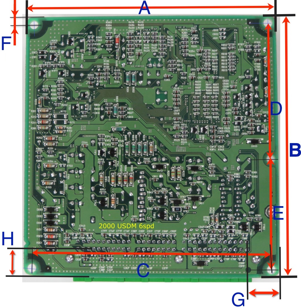
Not having a stock 99 ecu, anyone who can take these dimensions for me?
Also need the diameter of the mounting holes.
G and H are the distances of the solder pins of the connector relative to the edge of the board.
Also need the diameter of the mounting holes.
G and H are the distances of the solder pins of the connector relative to the edge of the board.
Last edited by WestfieldMX5; 02-23-2014 at 09:54 AM.
Reply
0
0

 02-23-2014, 10:52 AM
#6
Senior Member
Thread Starter
Join Date: Nov 2007
Location: Belgium
Posts: 999
Total Cats: 73
A friend asked me to make one for his 91.
Haven't decided yet, but once my own board is done, I might make one for him as well. It'll have jumpers to select between 1.6 and 1.8 to cover 90-97.
Once I have the measurements I can send off my order.
Did some more work in the meantime and updated the picture in the first post.
I won't be using an external bluetooth module or serial cable, so the DB9 is gone.
It gives me more room for a 2nd map sensor (constant baro).
I'll be installing an internal bluetooth module with some double sided tape and 4 wires like my current setup.
There's room enough for extra circuits so contemplating a shift light.
Reply
0
0
02-23-2014, 12:10 PM
#7

Check back in about 4-5 hours.
EDIT: Measurements are below;
A = 154.00
B = 159.10
C = 143.84
D = 83.00
E = 65.98
F = 5.00
G = 19.57 (board edge to C/L of pins)
H = 16.92 (board edge to C/L of pins)
Hole diameter = 5.08 (note: hole at intersection of D & E is 4.57, no idea why as all the screws are the same at 3.90) I'd use a 6mm circuit board drill in all the holes
Let me know if there's anything else you need.
Last edited by bahurd; 02-23-2014 at 04:21 PM.
Reply
0
0
03-03-2014, 05:49 PM
#9
Senior Member
Thread Starter
Join Date: Nov 2007
Location: Belgium
Posts: 999
Total Cats: 73
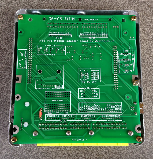
I added the connector for the 90-95 on the other side of the board.
The board now fits both 99-00 and 90-95 ecu cases depending on how it's oriented.
Here's the final design.
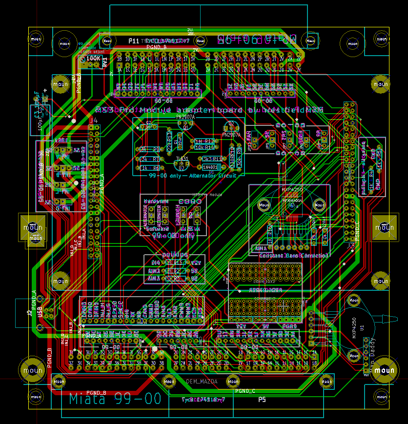
I don't have all components in 3D (and some are wrong like the male header pins), but this gives you an idea of what it'll look like

The board now fits both 99-00 and 90-95 ecu cases depending on how it's oriented.
Here's the final design.
I don't have all components in 3D (and some are wrong like the male header pins), but this gives you an idea of what it'll look like
Last edited by WestfieldMX5; 03-10-2014 at 07:56 AM. Reason: update board design
Reply
1
1
03-04-2014, 06:36 AM
#11
Senior Member
Thread Starter
Join Date: Nov 2007
Location: Belgium
Posts: 999
Total Cats: 73
Thanks Sven, I might be able to stuff 2nd MPX4250AP under the module, but I'd probably have to use non-standard header pins to lift the module a couple of mm. With standard header pins, there's probably not enough room, so I added a mapdaddy instead.
OTOH, it never hurts to add one even it means that the people who want one will have to use longer header pins. Mmm, you made me thinking some more about this. If I do this, there's plenty room for all kinds of extra stuff (shift light?)
Back to the drawing board - if I can put everything on hold as I already sent the files of to be made.
Any other suggestions?
EDIT: Followed your advice and added the 2nd map sensor for baro.
OTOH, it never hurts to add one even it means that the people who want one will have to use longer header pins. Mmm, you made me thinking some more about this. If I do this, there's plenty room for all kinds of extra stuff (shift light?)
Back to the drawing board
- if I can put everything on hold as I already sent the files of to be made.Any other suggestions?
EDIT: Followed your advice and added the 2nd map sensor for baro.
Last edited by WestfieldMX5; 03-10-2014 at 07:57 AM.
Reply
0
0
03-10-2014, 11:12 AM
#12
Senior Member
Thread Starter
Join Date: Nov 2007
Location: Belgium
Posts: 999
Total Cats: 73
I decided to draw a board for the 01-05 & 96-97 as well.
I'm not having them made right away (nobody has asked and I have no need for it), but it's really not that much work now that I have the basis.
If anyone has one of these ecu's, I'd appreciate it if they could verify the above dimensions of the mounting holes.
I tried googling, but I can't even find a picture of the oem pcb's for those years, so I don't know if the holes are in the same position.
Reply
0
0
03-25-2014, 12:44 PM
#14
Senior Member
Thread Starter
Join Date: Nov 2007
Location: Belgium
Posts: 999
Total Cats: 73
Lookie what arrived today 
This is so exciting!
The board can be used for 90-95 or 99-00 depending on how you orient it.
Putting one together for my 00 and a friend's 91 right now.
Left is for 99-00, when flipped upside down it's for 90-95 (center), right is an oem board for a 91.
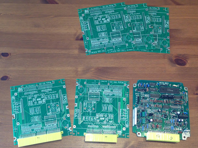
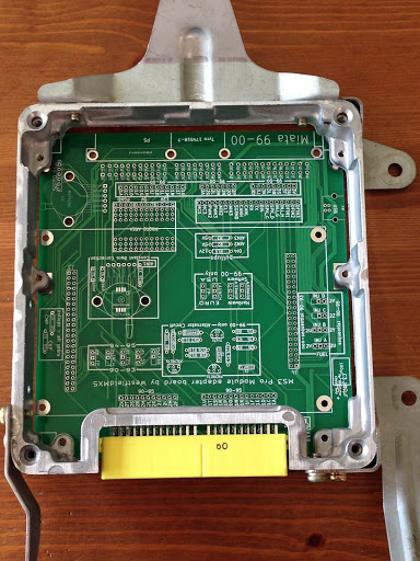
Testing the 91 case, perfect fit :-)
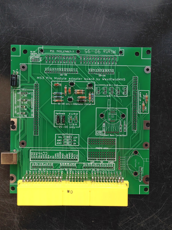
Here's the 99 setup, alternator circuit is soldered in, as is the usb connector and the ckp and cmp pullups.
Need to add the mapsensors and header pins for the MS3 Pro module.
The 2 overlapping holes on the left side is because of the different mounting hole in the 90-95 and 99-00 cases.
This is so exciting!
The board can be used for 90-95 or 99-00 depending on how you orient it.
Putting one together for my 00 and a friend's 91 right now.
Left is for 99-00, when flipped upside down it's for 90-95 (center), right is an oem board for a 91.
Testing the 91 case, perfect fit :-)
Here's the 99 setup, alternator circuit is soldered in, as is the usb connector and the ckp and cmp pullups.
Need to add the mapsensors and header pins for the MS3 Pro module.
The 2 overlapping holes on the left side is because of the different mounting hole in the 90-95 and 99-00 cases.
Last edited by WestfieldMX5; 03-28-2014 at 06:13 PM.
Reply
2
2

 03-28-2014, 06:16 PM
#18
Senior Member
Thread Starter
Join Date: Nov 2007
Location: Belgium
Posts: 999
Total Cats: 73
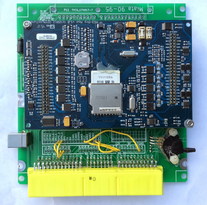
Finished the board today, everything fits perfectly
The yellow wires are extra outputs that I'm using. Most people will only need 3 wires (sequential spark and boost).
- spark_c and spark_d
- HC3 as boost control
- CLT output to my S2000 cluster
- AIN2 as oil pressure input
- HC1 as oil warning light output
I had a minimum order of 5 pieces. I'm keeping one for me, so I have the remaining ones for sale if anyone is interested.
More info and options on my website
Last edited by WestfieldMX5; 02-04-2017 at 09:41 AM.
Reply
0
0


